AMAZON multi-meters discounts AMAZON oscilloscope discounts
This laboratory work-guide is designed for use with the textbooks Electronic Devices by Thomas L. Floyd. The 43 experiments cover virtually every basic aspect of circuits containing rectifier and zener diodes; bipolar, field effect (JFET, MOSFET), and unijunction transistors; silicon-controlled rectifiers; operational amplifiers; and integrated-circuit voltage regulators, timers, and phase-locked loops.
The experiments are general enough to be easily integrated with any textbook on semiconductor devices at the electrical/electronics technology level. The experiments in this guide reinforce and expand upon the concepts presented in the classroom. The student is able to verify these concepts by performing detailed step-by-step experiments that are easily accomplished in a typical two- to three-hour lab session. In all cases, experimental measurements can be reasonably compared to theory. Although there are 43 experiments, the student will be expected to perform only a select number of them. It is not necessary to treat all the experiments separately; some may be conveniently combined as a single major experiment. Experiments 9 through 12, for example, concentrate on the biasing of bipolar transistors and can easily be consolidated.
Several features enhance the utility of this “work-guide”:
1. The purpose of each experiment is clearly defined. In addition, a short background summary on the operation of the circuit to be investigated is included.
2. At selected portions in a number of experiments, photographs of the oscilloscope’s display give students a picture of what they should observe on the screen.
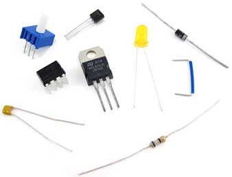
3. For each experiment, a list of required parts and test equipment is included. All parts are low in cost and are readily obtainable from a number of sources, including Radio Shack.
4. When appropriate, a summary of useful formulas is included to enable the student to compare measured results to theory.
5. A summary of “What You Have Done,” presented at the end of each experiment, restates and re-emphasizes the main points of the experiment as stated in the “Purpose and Background” section of the experiment.
6. There are “student response” sections at the end of each experiment. These sections are for the student to enter the objectives/purpose, the schematic diagram(s), all measured data (on a blank graph page when required), and the results and conclusions of the experiment.
7. Multiple-choice review questions are included.
CONTENTS
PERFORMING THE EXPERIMENTS
- Introduction
- Breadboarding
- Rules for Setting Up the Experiments
- Format for the Experiments
- Helpful Hints and Suggestions
- The Laboratory Report
EXPERIMENTS
1. The Diode
3. The Capacitor Input Rectifier Filter
7. The Zener Diode and Voltage Regulation
(below ... coming soon)
8. Using an Ohmmeter to Test Transistor Diode Junctions
9. Transistor Base Biasing
10. Transistor Emitter Biasing
11. Transistor Voltage-Divider Biasing
12. Transistor Collector-Feedback Biasing
13. The Common-Emitter Amplifier
14. The Common-Collector Amplifier (Emitter-Follower)
15. The Combination Common-Emitter Amplifier and Emitter-Follower
16. The Common-Base Amplifier
17. The JFET Drain Curve
18. The JFET Transfer Characteristic Curve
19. JFET Self-Bias
20. The Depletion-Mode MOSFET
21. The Enhancement-Mode MOSFET
22. VMOSFET Relay Driver
23. The Common-Source Amplifier
24. The Common-Drain Amplifier (Source-Follower)
25. The Class A Common-Emitter Power Amplifier
26 The Class B Push-Pull Emitter-Follower Power Amplifier
27. Amplifier Low-Frequency Response
28. The Silicon-Controlled Rectifier
29. The Unijunction Transistor
30. Op-Amp Slew Rate
31. Op-Amp Common-Mode Rejection
32. Op-Amp Inverting and Noninverting Amplifiers
33. Op-Amp Comparators
34. Op-Amp Differentiator and Integrator
35. The Phase-Shift Oscillator
36. The 555 Timer Astable Multivibrator
37. The Phase Detector
38. The 567 Phase-Locked Loop Tone Decoder
39. The Butterworth 2nd-Order Low-Pass Active Filter
40. The Butterworth 2nd-Order High-Pass Active Filter
41. The Active Band-Pass Filter
42. The Active Band-Stop Filter
43. The Integrated-Circuit Voltage Regulator
ADDIT.:
Required Parts and Equipment for the Experiments