AMAZON multi-meters discounts AMAZON oscilloscope discounts
PURPOSE AND BACKGROUND
The purpose of this experiment is to examine characteristics of a silicon diode. When the diode’s anode is at a higher potential than is the cathode, the diode is forward biased. For conventional current flow, current will flow through the diode from anode to cathode. For electron flow, current will flow from cathode to anode. Unlike a resistor, in which the current is directly (that is, linearly) proportional to the voltage across it, the diode is a nonlinear device. When the di ode is forward biased, a small but measurable voltage drop, called the barrier potential , occurs across the diode. For germanium diodes, this value is typically 0.3 V; for silicon diodes, it is approximately 0.7 V.
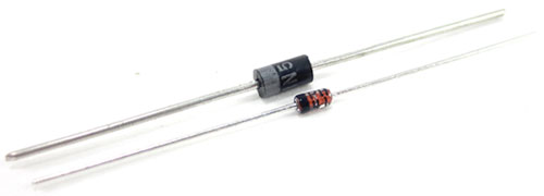
Above: Two types of diodes.
===
REQUIRED PARTS AND EQUIPMENT
Resistors (1/4 W):
- 10-ohm
- 100-ohm
- 1 k-ohm
- 1N914 (1N4148 or equivalent) silicon, small-signal diode
- 0—15 V dc power supply
- Signal generator
- Dual trace oscilloscope
- VOM
- Breadboarding socket
===
USEFUL FORMULA
The determination of Rf, the diode forward resistance, is shown graphically in Figure 1—1.
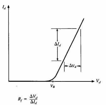
FIGURE 1—1 Graphic determination of diode forward resistance.
Rf=delta Vd/delta Id
PROCEDURE
1. Very often one can use a VOM to check quickly whether a diode is good or bad. Unless they have a specific function for this purpose, most DMMs are not able to perform this test properly. Using your VOM as an ohmmeter, first select a low-resistance meter range, such as the “R x 100” range. Then connect the positive lead of the VOM to the diode’s anode terminal while the negative lead is connected to the diode’s cathode terminal, as shown in Figure 1-2A. (Most diodes have a single colored band, several bands, the diode symbol, or the letter “K” at one end to indicate the cathode terminal.) The VOM’s internal battery then forward biases the diode. Note the resistance reading.
If a DMM with a “ diode check” feature is used, the display usually indicates the voltage drop across a good diode from anode to cathode when it is forward biased. When reverse biased, the DMM generally indicates some form of out-of-range condition, such as a blinking display or the letters “OL.”
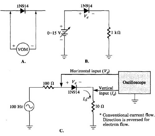
FIGURE 1-2 Schematic diagram of circuits.
2. Now reverse the VOM’s leads so that the meter’s positive terminal is connected to the cathode terminal of the diode, which is now reverse biased. Note the resistance reading.
The reading you have just obtained should be much higher (typically several hundred thousand ohms) compared to the resistance reading of Step 1, which is typically a few hundred ohms or less. Consequently, the diode exhibits a low forward resistance while having a high, or nearly infinite, reverse resistance. The actual resistance readings obtained are not as important as their relationship to each other. If both readings indicate virtually the same low resistance, then the diode is shorted; if a very high resistance is obtained in both directions, the diode is open.
When measuring resistances, some VOMs have the polarity of their leads reversed from the normal sense. That is, the positive lead is actually wired to the internal battery’s negative terminal. In this case, the forward and reverse resistance readings will be the opposite of those indicated in these two steps. When it functions as a voltmeter or an ammeter, this type of VOM has its leads internally connected in the normal sense.
3. Wire the circuit shown in Figure 1-2B. Adjust the dc power supply to give the voltages across the 1-k-ohm resistor. For each voltage, measure and record the dc voltage drop (Vd) across the diode. The diode current is also the current flowing through the 1 k-ohm resistor. Determine the diode current by using Ohm’s law in each case.
4. Plot the resulting diode curve (diode current versus voltage) on the graph page in this experiment. Graphically determine the diode’s barrier potential (VB) and forward resistance (RF), recording your results.
5. Disconnect the power from the breadboard and wire the circuit shown in Figure 1—2C. In this part, the oscilloscope is set up to function as an X-Y plotter. Set the oscilloscope controls to the following approximate settings:
Vertical (or Y) input sensitivity: 10 mV/division, dc coupling
Horizontal (or X) input sensitivity: 1 V/division, dc coupling
6. After the oscilloscope has warmed up, center the trace dot at the center of the scope’s screen. Adjust the sine wave frequency of the signal generator to approximately 100 Hz, and vary the generator’s output level so that you observe the characteristic diode curve similar to the one plotted in Step 4. The oscilloscope display should be similar to that shown in Figure 1-3. If it is not, the leads of the oscilloscope may be interchanged or there may be wiring error.
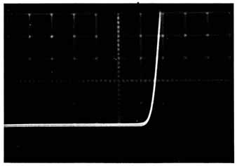
FIGURE 1-3
The horizontal input measures the voltage across the diode (Vd), neglecting the small voltage drop across the 10-ohm resistor. The vertical input measures the voltage drop across the 10-ohm resistor. By Ohm’s law, the vertical input can be made to show the diode current (Id). If the vertical sensitivity is 10 mV/division, then in terms of the current through the 10-ohm resistor, which is the same as the diode current,
Vertical sensitivity = 10 mV/division / 10-ohm
= 1 mA/division
7. As in Step 4, from the oscilloscope’s display graphically determine the diode’s barrier potential and forward resistance, recording your results. How does this compare with Step 4 for the same diode?
WHAT YOU HAVE DONE
This experiment examined the characteristics of a silicon diode. You learned how to properly test a diode using a VOM or DMM, and how to determine the diode’s barrier potential and forward resistance. By graphing the diode’s forward characteristic, you observed that the diode is a nonlinear device.