AMAZON multi-meters discounts AMAZON oscilloscope discounts
PURPOSE AND BACKGROUND
The purpose of this experiment is to demonstrate the operation of both the half-wave and the full-wave diode voltage doublers. Diode voltage doublers are used to double the peak rectified voltage with out the necessity of increasing the input transformer’s voltage rating. The half-wave voltage doubler is actually a positive clamper followed by a half-wave rectifier with a capacitor input filter (peak detector). It charges a series capacitor on each positive half-cycle. Consequently, the ripple frequency is the same as the input frequency.
The full-wave voltage doubler, on the other hand, has the same rectified peak output voltage as the half-wave doubler. It charges one of two series capacitors on the first half-cycle, while the other capacitor is charged on the remaining half-cycle. There fore, it has a ripple frequency that is twice the input frequency. Consequently, for the same filter time constant, the peak-to-peak ripple voltage is smaller when a full-wave voltage doubler is used.
= = =
REQUIRED PARTS AND EQUIPMENT
- 10-kOhm resistor, 1/4 W
- Two 100-uF capacitors, 25 V
- Two 1N4001 silicon rectifier diodes
- Dual trace oscilloscope
- VOM or DMM
- 12.6-V rms secondary center-tapped transformer
- Breadboarding socket
= = =
USEFUL FORMULAS
Output voltage
(1) V = 2V — 2Vd
Ripple frequency
(2) f_ripple = f (half-wave doubler)
(3) f_ripple = 2f (full-wave doubler) Diode peak inverse voltage
(4) PIV = 21T
PROCEDURE
1. Wire the half-wave diode voltage doubler shown in the schematic diagram of Figure 6—1A.
2. Set your oscilloscope to the following approximate settings:
Channels 1 and 2: 5 V/division, dc coupling
Time base: 2 ms/division
Apply the 117-V rms ac, 60-Hz power line voltage to the transformer’s primary.
3. You should see two sine waves on the oscilloscope’s display. On Channel 1 at point A, it should show the secondary voltage of the transformer. Measure the positive peak voltage V and the frequency fin, recording these values.
On Channel 2, you should see the same waveform at point B, but it should be positively clamped near zero volts and the positive peak voltage should be nearly twice that of the trans former’s secondary voltage. Measure this peak voltage, V1, and record this value.
4. Now take the Channel 1 probe and connect it to the 10-kOhm load resistor (point C). You should see two signals similar to those shown in Figure 6—2. Measure the dc voltage VDC across the 10-kOhm resistor with a VOM or DMM, and record this value in …
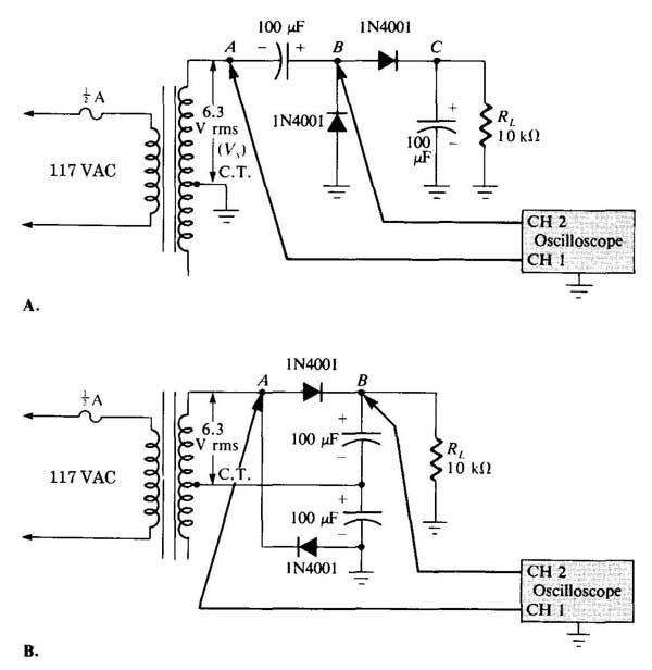
FIGURE 6-1 Schematic diagram of circuits.
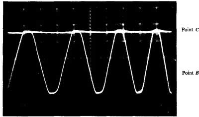
FIGURE 6-2
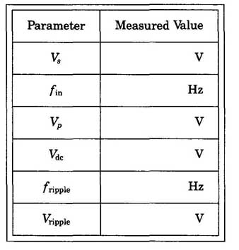
TABLE 6-1 Half-wave diode voltage doubler.
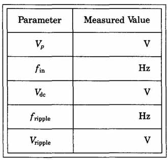
TABLE 6-2.
REVIEW QUESTIONS FOR EXPERIMENT
1. For the half-wave voltage doubler of Figure 6—1A, the output ripple frequency is:
(a) one-half the input frequency
(b) the same as the input frequency
(c). twice the input frequency
2. For the full-wave voltage doubler of Figure 6—1B, the output ripple frequency is:
(a). one-half the input frequency
(b) the same as the input frequency
(c). twice the input frequency
3. If the peak input voltage is 10 V, then the peak inverse voltage of both diodes of a half-wave voltage doubler is:
(a). 5 V (b) 10 V (c) 20 V (d) 40 V
4. If the peak input voltage is 10 V, then the peak inverse voltage of both diodes of a full-wave voltage doubler is:
(a). 5V (b) 10V (c) 20V (d) 40V
5. For the half-wave voltage doubler of Figure 6—1A, the capacitor and diode arrangement between points A and B is a:
(a). peak detector (b) negative limiter
(c). positive clamper (d) negative clamper