AMAZON multi-meters discounts AMAZON oscilloscope discounts
PURPOSE AND BACKGROUND
The purpose of this experiment is to demonstrate the operation a diode clamper. Like the diode clipper, the clamper is a wave-shaping circuit, but it adds a dc level to the input waveform. Thus, the clamper is often referred to as a dc restorer. However, unlike that of the clipper, the shape of the input signal of a clamper is not changed.
= = =
REQUIRED PARTS AND EQUIPMENT
- 10-kOhm resistor, 1/4 W
- 10-uF electrolytic capacitor, 25V
- 1N4001 silicon rectifier diode
- Signal generator
- Dual trace oscilloscope
- Breadboarding socket
= = =
USEFUL FORMULAS
Clamper time constant
(1) 1ORLC >>
Peak output voltage
(2) V = (peak-to-peak) — Vd
PROCEDURE
1. Wire the clamper circuit shown in the schematic diagram of Figure 5-1. Set your oscilloscope to the following approximate settings:
Channels 1 and 2: 2.0 V/division, dc coupling Time base: 0.2 ms/division
Without any input signal connected to the breadboard, position the two lines on the ‘scope display so that they are at the same level (zero volts).
2. Now connect the signal generator to the breadboard. Adjust the signal generator’s output level at 5 V peak-to-peak at a frequency of 1 kHz. You should see two sine waves. Notice that the clamper’s output signal level is above the input’s. This action is that of a positive clamper, so that the input waveform is shifted upward. This effect is the same as that obtained by adding a dc voltage onto the input waveform. On the data page at the end of this experiment, sketch both the input and the output waveforms, showing the positive and negative peak values for both.
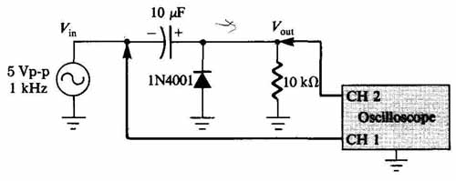
FIGURE 5—1 Schematic diagram of circuit.
3. Note that the clamping action is not perfect. The negative peaks of the output waveform are clamped not at zero volts, but at a small negative voltage. When the input waveform goes negative at a level greater than the barrier potential of the diode, the diode is forward biased, the equivalent of a short circuit in series with a small dc voltage source. Thus, approximately 0.5 to 0.7 volt (the barrier potential for a silicon diode, Vd) is dropped across the diode, while the remainder of the peak negative voltage (Vp — Vd) charges the 10-uF capacitor. On the next positive-going half-cycle, the diode is reverse biased, looking like an open circuit, and the voltage stored on the capacitor is then added to the time-varying input voltage. The result is that the peak output voltage is now approximately equal to the peak-to-peak input voltage, less the voltage drop of the diode.
4. Increase the peak-to-peak input voltage. What happens? Although the peak-to-peak output voltage increases, its negative peak remains clamped at the same negative voltage level measured in Step 3. You should find that the positive peak output voltage is again approx. the peak-to-peak input voltage.
5. Now reverse the polarity of the diode in the circuit, and repeat Steps 2, 3 and 4. Now what happens?
The behavior is opposite that of the positive clamper. Notice that the clamper’s output signal level is below the input’s. This action is that of a negative clamper, so the input waveform is shifted downward. This effect is the same as that obtained by adding a negative dc voltage onto the input waveform. On the data page at the end of this experiment, sketch both the input and the output waveforms, showing the positive and negative peak values for both.
6. Again you should notice that the clamper action is not perfect. The positive peaks of the output waveform are clamped not at zero volts, but at a small positive voltage.
7. Increase the peak-to-peak input voltage. What happens?
You should see that although the peak-to-peak output volt age increases, its positive peak remains clamped at the same positive voltage level measured in Step 6. You should find that the negative peak output voltage is again approximately equal to the peak-to-peak input voltage.
WHAT YOU HAVE DONE
This experiment demonstrated the operation of a diode clamper. This circuit does not change the waveshape of the input signal, but merely adds a dc level to the input waveform.