AMAZON multi-meters discounts AMAZON oscilloscope discounts
PURPOSE AND BACKGROUND
The purpose of this experiment is to demonstrate the operation of a diode limiter. Diode limiters are wave-shaping circuits in that they are used to prevent signal voltages from going above or below certain levels. The limiting level may be either equal to the diode’s barrier potential or made variable with a DC source voltage. Because of this clipping capability, the limiter is also called a clipper.
= = =
REQUIRED PARTS AND EQUIPMENT
- 15-kOhm resistor, 1/4 W
- 5-kOhm potentiometer, or 10-turn “trimpot”
- 1N4001 silicon rectifier diode
- 0-15 V dc power supply
- Signal generator
- Dual trace oscilloscope
- Breadboarding socket
= = =
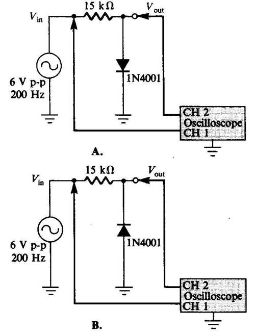
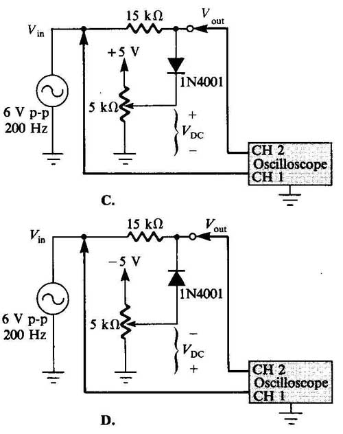
FIGURE 4-1 Schematic diagram of circuits.
1. Wire the limiter circuit shown in the schematic diagram of Figure 4-1A. Set your oscilloscope to the following approximate setting:
Channels 1 and 2: 1 V/division, dc coupling
Time base: 1 ms/division
Without any input signal connected to the breadboard, position the two lines on the oscilloscope’s display so that they are at the same level (that is, zero volts).
2. Now connect the signal generator to the breadboard. Adjust the signal generator’s output level at 6 V peak-to-peak at a freq. of 200 Hz. You should see two waveforms similar to those shown in Figure 4-2. Notice that the positive peaks of the limiter’s output waveform are removed, or clipped off. Notice also that the clipping level is not perfect; the positive peaks are clipped not at zero volts, but at a small positive voltage. When the input waveform goes positive at a level greater than the barrier potential of the diode, the diode is forward biased, the equivalent of a short circuit in series with a small dc voltage source. Thus, approximately 0.5 to 0.7 volt (the barrier potential for a silicon diode) is dropped across the diode. When the input waveform goes negative, the diode looks like an open circuit, and essentially all of the input appears at the output. Such an arrangement is called a positive limiter because the circuit limits the positive peaks of the input waveform. On the data page at the end of this experiment, sketch your clipped waveform, showing the positive and negative peak values.
3. Now reverse the polarity of the diode in the circuit, as shown in Figure 4-1B. How does this waveform compare with that of Step 2?
The behavior is opposite that of the positive limiter. The waveform has all negative peaks of the input signal removed, as shown in Figure 4-3. Again, notice that the clipping level is not perfect; the negative peaks are clipped not at zero volts, but at a small negative voltage. Such an arrangement is called a negative limiter because the circuit clips off the negative peak of the input waveform. On the data page at the end of this experiment, sketch your clipped waveform, showing the positive and negative peak values.
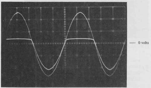
FIGURE 4-2
4. Now connect the circuit of Figure 4-1C. Apply power to the breadboard and adjust the potentiometer so that the dc voltage (Vdc) is +1.5V. Connect the signal generator, set at v. peak-to-peak, to the breadboard. What do you notice about the output of the limiter?
The clipping level is higher than that measured in Step 2. The circuit uses a dc source voltage to bias, or set, the clipping level. Consequently this arrangement is called a positive-biased limiter. On the data page at the end of this experiment, sketch the clipped waveform, showing the and negative peak values.
Note that the positive clipping level is the dc source volt age plus the diode’s barrier potential. For the diode to become forward biased, the positive peaks of the input signal must be greater than the dc source voltage and the diode’s barrier potential.
5. Vary the resistance of the potentiometer from one extreme to the other. What happens to the clipping level?
The clipping level changes with the setting of the potentiometer. At one extreme, when the dc bias voltage (VDC) is zero, the positive clipping level should be the same as was measured in Step 2. At the other extreme, there should be no clipping, as the dc bias voltage is about + 5 V. Since the input positive peaks are at +3.0 V, the diode is effectively reverse biased and looks like an open circuit, and thus the input appears unchanged at the output.
6. Now reverse the polarities of both the diode and the dc power supply in the circuit, as in Figure 4-1D. Adjust the pot voltage so that dc voltage (Vdc) is -1.5v. Connect the signal generator, set at 6 V peak-to-peak, to the breadboard. What do you notice about the output of the limiter?
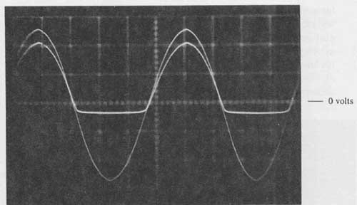
FIGURE 4-3
Note that the clipping level is lower than that measured in Step 3. The circuit uses a dc source voltage to bias, or set, the clipping level. Consequently, this arrangement is called a negative-biased limiter. On the data page at the end of this experiment, sketch the clipped waveform, showing the dc positive and negative peak values.
Notice also that the negative clipping level is the dc source voltage plus the diode’s barrier potential. For the diode to be come forward biased, the negative peaks of the input signal must be greater than the dc source voltage and the diode’s barrier potential.
7. Vary the resistance of the potentiometer from one extreme to the other. What happens to the clipping level?
The clipping level changes with the setting of the potentiometer. At one extreme, when the dc bias voltage (VDC) is zero, the positive clipping level should be the same as was measured in Step 3. At the other extreme, there should be no clipping, as the dc bias voltage is about —5 V. Since the input negative peaks are at —3.0 V, the diode is effectively reverse biased and looks like an open circuit, and thus the input appears unchanged at the output.
WHAT YOU HAVE DONE
This experiment demonstrated the operation of a diode limiter, or clipper, which limits signal voltages from going above or below preset levels. You worked with both positive and negative limiters whose clipping level was equal to the diode’s barrier potential. In addition, it was shown how to make the clipping level variable by using an external dc voltage source.