AMAZON multi-meters discounts AMAZON oscilloscope discounts
PURPOSE AND BACKGROUND
The purpose of this experiment is to demonstrate the operation of a capacitor input filter when connected to the output of a full-wave bridge rectifier. The filter, which consists of a single resistor and capacitor in parallel, smooths out the pulsating output voltage of the rectifier.
==
REQUIRED PARTS AND EQUIPMENT
- 1-kOhm resistor, 1/2 W
- Capacitors (25 V):100 uF
- Capacitors (25 V):470 uF
- Four 1N4001 silicon rectifier diodes
- 12.6-V rms secondary center-tapped transformer
- Dual trace oscilloscope
- VOM or DMM
- Breadboarding socket
==
USEFUL FORMULAS
dc output voltage
(1) Vd = (i — O (when RLC >>
rms ripple voltage
(2) Vr =. (when RLC >>
Percent ripple factor
(3). %r =. Vdc x 100%
PROCEDURE
1. Wire the full-wave bridge rectifier circuit shown in Figure 3—1, paying careful attention to the polarity of the 1N4001 diodes. You should be very careful to be sure that your connections to the 117-V primary of the transformer are properly protected so that you will not get a shock by accidentally touching them. Furthermore, you should have a 1/2-A fuse on the primary side of the transformer. Note that neither of the transformer’s primary leads is grounded, while the center-tapped secondary lead is not used. Also observe the polarity of the 100-uF filter capacitor.
2. Apply 117 VAC (rms) to the transformer’s primary leads. With one oscilloscope channel set to dc coupling, connect the probe to the ungrounded junction of the 1-kOhm resistor and the 100-uF capacitor. If everything is working properly, you should obtain the waveform shown in Figure 3—2.
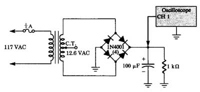
FIGURE 3—1 Schematic diagram of circuit.
3. With the oscilloscope, measure the peak output voltage (Vo) across the 1-kOhm resistor and the 100- capacitor. With your VOM or DMM, measure the dc voltage (Vat) and compute the expected dc voltage, rms ripple, and percentage ripple factor using Equations 1, 2, and 3. Record all results.
4. Turn off the 117-VAC primary voltage, and then place a piece of wire or a screwdriver across both capacitor leads, which, in effect, discharges the capacitor. With the relatively low secondary voltages used in this experiment, the risk of getting a severe shock is small. However, this practice is a good-habit to acquire when working with power supplies and filters. By discharging (that is, shorting) the filter capacitor after the supply voltage has been turned off or removed, you then eliminate the possibility of coming in contact with a fully charged capacitor, which, depending on its capacitance and voltage, can deliver quite an unexpected jolt.
Remove the 100-uF capacitor from the circuit and replace it with a 470-uF capacitor. Then apply 117 VAC to the trans former’s primary
5. With your oscilloscope, measure the peak output voltage across the 1-kOhm resistor and the 470-uF capacitor. As in Step 3, mea sure the dc output voltage and, using Equations 1, 2, and 3, calculate the expected values for the dc voltage, rms ripple voltage, and percent ripple factor. Record all results.
6. If you have wired the circuit correctly, you should now observe very little ripple voltage on the oscilloscope’s display. Now change the input to ac coupling, and increase the sensitivity of the oscilloscope channel to about 10 mV/division so that you can clearly see the output ripple.
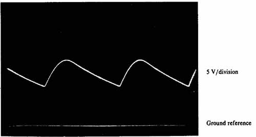
FIGURE 3—2: base: 2 ms/division.
7. For each capacitor value, compare your values for dc output voltage, rms ripple voltage, and percent ripple factor. When you increase the value of the filter capacitor, what happens to the dc output voltage, rms ripple voltage, and percent ripple factor?
For a fixed load resistance of 1 kOhm increasing the capacitance of the input filter capacitor should increase the dc output voltage toward the peak output voltage while decreasing both the rms ripple voltage and the percent ripple factor.
WHAT YOU HAVE DONE
This experiment demonstrated the operation of a capacitor input filter when connected to the output of a full-wave bridge rectifier. The filter, using a parallel resistor-capacitor circuit, smooths out the pulsating output voltage of the rectifier. As the RC time constant of the filter was made larger, the ripple voltage of the filter was reduced further.