AMAZON multi-meters discounts AMAZON oscilloscope discounts
Power conversion systems are commonly referred to by the function they perform. Power conversion takes place in the load of an electrical power system. Common types of power system loads are those that convert electrical energy into heat, light, or mechanical energy. There are various types of lighting, heating, and mechanical loads used in industry, commercial buildings, and homes. Several of these power conversion systems will be discussed in Sections 12, 13, and 14.
TERMINOLOGY
This Section deals with heating systems. After studying this Section, you should have an understanding of the following terms:
- Resistive Heating
- Induction Heating
- Dielectric Heating
- Electric Welding
- Resistance Welding
- Arc Welding
- Induction Welding
- SCR Contactors
- Electric Heating Systems
- British Thermal Units (Btus)
- Design Temperature Difference
- Degree Days
- Thermal Resistance (R)
- Coefficient of Heat Transfer (U)
- Heat Pump
- Air Conditioning System
BASIC HEATING LOADS
Most loads that are connected to electrical power systems produce a certain amount of heat, mainly as the result of current flow through resistive devices. In many instances, heat represents a power loss in the circuit, since heat energy is not the type of energy that the system was intended to produce. Lights, for instance, produce heat energy as well as light energy.
The conversion of electrical energy to heat energy in a light-producing load reduces the efficiency of that load device, since not all of the available source energy is converted to light energy. There are, however, several types of power conversion systems that are mainly heating loads. Their primary function is to convert electrical energy into heat energy. Some basic systems include resistance heating, inductive heating, and dielectric (capacitive) heating.
Resistance Heating
Heat energy is produced when an electrical current flows through a resistive material. In many instances, the heat energy produced by an electrical current is undesirable; however, certain applications require con trolled resistance heating. Useful heat may be transferred from a resistive element to a point of utilization by the common methods of heat transfer-convection, radiation, or conduction. A heating-element enclosure is needed to control the transfer of heat by convection and radiation. For heat transfer by conduction, the heating element is in direct contact with the material to be heated. Actual heat transfer usually involves a combination of these methods.
FIG. 1 illustrates the principle of resistance heating. The self contained heating element uses a coiled resistance wire, which is placed inside a heat-conducting material and enclosed in a metal sheath. This principle may be used to heat water, oil, the surrounding atmosphere, or various other media. This type of heater may be employed in the open air or immersed in the media to be heated. The useful life of the resistance elements depends mainly upon the operating temperature. As the tempera ture increases, the heat output also increases. Basically, the heat energy produced is dependent upon the current flow and the resistance of the element; it can be calculated as current squared times resistance (I^2 R).
Induction Heating
The principle of induction heating is illustrated in FIG. 2. Heat is produced in magnetic materials when they are exposed to an alternating current (AC) field. In the example shown, current is induced in the material heated by electromagnetic induction. This is brought about by the application of an AC to the heating coil. The material to be heated must be a conductor in order for current to be induced. Ordinarily, a high frequency AC source in the range of 100-500 kHz is used to produce a high heat output. This high heat output is due to greater amounts of induced voltage.
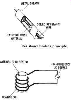
(top) FIG. 1. Resistance heating principle; (bottom) FIG. 2. Induction heating
principle
As the magnetic field created by the high-frequency AC source moves across the material to be heated, the induced voltage causes eddy currents (circulating currents) to flow in the material. Heat results because of the resistance of the material to the flow of the eddy currents. The heat is produced rapidly by this method, which is an advantage.
The major application of the induction-heating process is in metal working industries, for such processes as hardening, soldering, melting, and annealing of metals. Compared to that of other methods of heating the heat production of this process is extremely rapid. The area of the met al that is actually heated can be controlled by the size and position of the heating coils of the induction heater. This type of control is difficult to accomplish by other methods. Induction furnaces use the induction-heating principle.
By varying the frequency of the voltage applied to the induction heater windings, it is possible to vary the depth of heat penetration into the heated metal. At higher frequencies the heat produced by the induced current from the heating coils will not penetrate as deeply, because of the so-called "skin effect." Thus, heat will penetrate more deeply at lower frequencies. When heat must be localized onto the surface of a material only for example, for surface hardening of a metal-higher frequencies are used. The cost of higher-frequency induction heaters is greater, because more complex oscillator circuits are required to produce these frequencies.
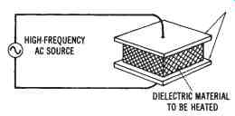
FIG. 3. Capacitive heating principle
Dielectric (Capacitive) Heating
Induction heating can only be used with conductive materials. There fore, some other method must be used to heat nonconductive materials.
Such a method is illustrated in FIG. 3 and is referred to as dielectric or capacitive heating. Nonconductors may be heated by placing them in an electrostatic field, created between two metal electrodes that are supplied by a high-frequency AC source. The material to be heated becomes the dielectric or insulation of a capacitive device. The metal electrodes constitute the two plates.
When high-frequency AC is applied to a dielectric heating assembly, the changing nature of the applied AC causes the internal atomic structure of the dielectric material to become distorted. As the frequency of the AC increases, the amount of internal atomic distortion also increases.
This internal friction produces a large amount of heat in the nonconductive material. Frequencies in the 50-Mhz range may be used for dielectric heating. Dielectric heating produces rapid heating, which is spread evenly throughout the heated material. Common applications of this heating method are the gluing of plywood and the bonding together of plastic sheets.
ELECTRICAL WELDING LOADS
Electrical welding is another common type of a heat-producing power conversion system. The types of electrical welding systems include resistance welding, electric arc welding, and induction welding.
Resistance Welding
Several familiar welding methods, such as spot welding, seam welding, and butt welding, are resistance welding processes. All of these processes rely upon the resistance heating principle. Spot welding, illustrated in FIG. 4A, is performed on overlapping sheets of metal, which are usually less than 1/4-inch thick. The metal sheets are clamped between two electrodes, and an electrical current is passed through the electrodes and metal sheets. The current causes the metals to fuse together. The instantaneous current through the electrodes is usually in excess of 5000 amperes, while the voltage between the electrodes is less than 2 volts.
Seam welding, shown in FIG. 4B, is accomplished by passing sheets of metal between two pressure rollers, while a continuously interrupted current is passed through the electrodes. The operational principle of seam welding is the same as that of spot welding. Several other similar methods, which are referred to as butt welding, edge welding, and projection welding, are also commonly used.
Electric Arc Welding
While resistance welding utilizes pressure on the materials to be welded, electric arc welding produces welded metals by localized heating without pressure, as shown in FIG. 5. An electric arc is created when the electrode of the welder is brought in contact with the metal to be welded. Carbon electrodes are used for DC or AC arc welding of nonferrous metals and alloys. Not all metals can be welded by the arc welding process. When metals are welded together, part of the metals to be welded are melted, creating a metal pool that is added to, when necessary, by the use of a filler rod. The puddle (molten metal pool) then fills in the gap (arc crater) that was created by the arc of the electrode. Various types and various current-voltage ratings of electric arc welders are available.
A smaller amount of current is required for arc welding than for resistance welding. The currents may range from 50 to 200 amperes, or higher for some applications. Voltages typically range from 10 to 50 volts. An electric arc welder may be powered by a portable generator, a storage-battery unit, a step-down transformer, or a rectification unit.
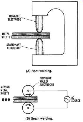
FIG. 4. Resistance welding methods: (A) Spot welding, (B) Seam welding
Induction Welding
The induction welding process uses the principle of induction heating to fuse metals together. High-frequency AC is applied to a heating coil, into which the materials to be welded are placed. Tubular metal is often welded in this way.
POWER CONSIDERATIONS FOR ELECTRIC WELDERS
Electric welders are rather specialized types of equipment, since they use very high amounts of current at low voltage levels. They have a peculiar effect on the power system operation. They draw large amounts of current for short periods of time. Silicon-controlled rectifiers (SCRs) are commonly used to control the starting and stopping of the large currents associated with electric welders. The current rating of these devices must be very high, sometimes in the range of 1000 to 100,000 amperes, and the power distribution equipment must be able to handle these high currents. SCRs are discussed in Section 17.
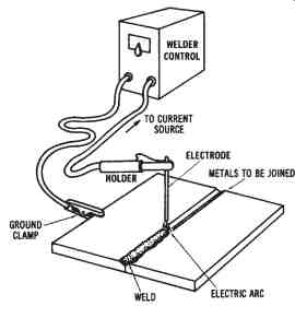
FIG. 5. Electric arc welding
FIG. 6 illustrates a typical electric welding system. The AC power supplied from the branch circuit of the power system is either stepped down by a transformer to deliver AC voltage to the welder, or rectified to produce DC voltage for DC welders. In either type of machine, an SCR contactor may be used to control the on and off time of the welder.
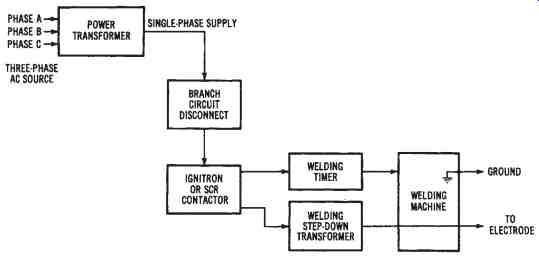
FIG. 6. Block diagram of a typical electric welding system
SCR Contactors
SCR contactors are electronic control devices designed to handle large amounts of current. SCRs are triggered or turned on by pulses sup plied by the timing or sequencing circuits of the welder. The SCRs are usually cooled by circulating water. The operating principles of SCRs are discussed in Section 17.
ELECTRIC HEATING AND AIR CONDITIONING SYSTEMS
A very important type of electrical power conversion is that which takes place in the heating and air conditioning systems of homes, industries, and commercial buildings. These loads convert a high percentage of the total amount of electrical power that is furnished. Although natural gas and fuel oil heating systems are still used, electrical heating is becoming more prevalent each year. Air conditioning systems are also becoming more commonly used to cool buildings. The use of electric heating and air conditioning systems has made us even more dependent upon electrical power. We now use electrical power to maintain a comfortable environment inside buildings.
Basics of Electric Heating
There are several important factors that you must understand in order to have a knowledge of electric heating. Heat is measured in British thermal units (Btus). One Btu is the amount of heat required to raise the temperature of one pound of water one degree Fahrenheit. Heat energy in the amount of 3.4 Btus per hour is equivalent to one watt of electrical energy.
Another basic factor to be considered in the study of electric heating is design temperature difference. This is the difference between inside and outside temperatures in degrees Fahrenheit. The outside tempera ture is considered to be the lowest temperature that is expected to occur several times a year. The inside temperature is the desired temperature (thermostat setting).
A factor used in conjunction with design temperature difference is called degree days. The degree-day factor is used to determine the aver age number of degrees that the mean temperature is below 65°F. These data are averaged over seasonal periods for consideration in insulating buildings.
Importance of Insulation
The insulation of a building is a very important consideration in electric heating systems. Insulation is used to oppose the escape of heat. The quality of insulation is expressed by a thermal resistance factor (R). The total thermal resistance of a building is found by considering the thermal resistance of the entire structure (wood, concrete, insulation, et cetera). The inverse of thermal resistance is called the coefficient of heat transfer (U), which is an expression of the amount of heat flow through an area, expressed in Btus per square foot per hour per degree Fahrenheit. The following formulas are used in the conversion of either U or R to electrical units (watts):
1
thermal resistance = ------------- coefficient of heat transfer
coefficient of heat transfer
watts = ------------ 3.4 or:
watts = 0.29 × U
The manufacturers of insulation can supply various tables that can be used to estimate the heat loss that can occur in buildings of various types of construction. Heat loss occurs particularly through the windows and doors of buildings. The periodic opening of doors also has a considerable effect on heat loss. A building must have sufficient insulation to reduce heat loss; otherwise, electrical heating and air conditioning systems will be very inefficient. The heat loss of a building depends primarily upon the building construction, and upon the design temperature difference factor in the area where the building is located. Buildings made of concrete have a different amount of heat loss than those of a wood-frame construction. Heat loss will occur through the walls, floors, windows, and ceilings. Each of these must be considered when estimating the heat loss of a building.
The following sample problem will help you to understand the importance of adding insulation to a building.
Sample Problem:
Given: a building constructed to provide the following thermal resistance (R) factors:
(a) Exterior shingles are R = 0.80
(b) Plywood sheathing is R = 0.75
(c) Building paper used is R = 0.04
(d) Wall structure is R = 0.85
(e) Wall plaster is R = 0.35
(f) Insulation is R = 11.0
Find: the total thermal resistance (R), the coefficient of heat transfer (U), and the watts (W) of heat loss both with and without the insulation.
Solution (without insulation):
You can see from the results of this problem that the adding of insulation into the walls of a building has a great effect upon heat loss. The insulation has a much greater effect in controlling heat loss than do the construction materials used for the building.
Electric Heating and Cooling Systems
Several types of electric heating systems are used today. Some common types are baseboard heaters, wall- or ceiling-mounted heaters, and heat pumps. Most of these systems use forced air to circulate the heat.
Some electric heaters have individual thermostats, while others are connected to one central thermostat that controls the temperature in an entire building. The possibility of having temperature control in each room is an advantage of electric heating systems.
Heat Pumps
In recent years, the heat pump has become very popular as a combination heating and cooling unit for buildings. The heat pump is a heat transfer unit. When the outside temperature is warm, the heat pump acts as an air conditioning unit and transfers the indoor heat to the outside of the building. This operational cycle is reversed during cool outside temperatures. In the winter, the outdoor heat is transferred to the inside of the building. This process can take place during cold temperatures, since there is always a certain amount of heat in the outside air, even at subzero temperatures. However, at the colder temperatures, there is less heat in the outside air.
Thus, heat pumps transfer heat rather than produce it. Since heat pumps do not produce heat, as resistive-heating units do, they are more economical in terms of energy conservation. Heating and cooling are reversible processes in the heat-pump unit; thus, the unit is self-contained.
The reversible feature of heat pumps reduces the space requirement for separate heating and cooling units. Another advantage is that the change over from heating to cooling can be made automatically. This feature might be desirable during the spring and autumn seasons, in the many areas where temperatures are very variable. In extremely cold areas, the heat pump can be supplemented by an auxiliary resistance-heating unit.
This auxiliary unit will operate when the outside temperatures are very cold, and will be useful in maintaining the inside temperatures at a comfortable level. Air is circulated past these heating elements into the heat vents of the building.
Heat pumps are used for residential as well as commercial and industrial applications, and they are being used more extensively each year.
FIG. 7 shows a simplified circuit arrangement of a heat pump, in which a compressor takes a refrigerant from a low-temperature, low-pres sure evaporator and converts it to a high temperature and a high pressure.
The refrigerant is then delivered to a condenser, in much the same way as in a refrigerator.
Air Conditioning Systems
The increased use of air conditioning systems provides greater com fort in homes, industrial plants, and commercial facilities. Most air conditioning units are used for the purpose of controlling the inside tempera ture of buildings, so as to make working and living conditions more comfortable. However, many units are used to cool the insides of various types of equipment. Both air temperature and relative humidity are changed by air conditioning units. In the design of air conditioning systems, all heat producing items in the immediate environment must be considered. Body heat, electrical appliances, and lights represent some common sources of heat. The diffusion of heat takes place through floors, walls, ceilings, and the windows of buildings. A simplified diagram of a room air conditioning unit is shown in FIG. 8.
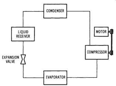
FIG. 7. A simplified heat-pump circuit diagram
Considerations for Heating Loads
Heating systems used for residential, commercial, and industrial applications are usually referred to as HVAC systems. This means heating ventilation and air conditioning system. The electrical power requirement for HVAC systems is a major concern for electrical system design for a building. Electrical HVAC systems provide individual thermostatic temperature control, have long equipment life, and are safe to use. A well insulated building is necessary to reduce heat loss for economical use of HVAC systems.
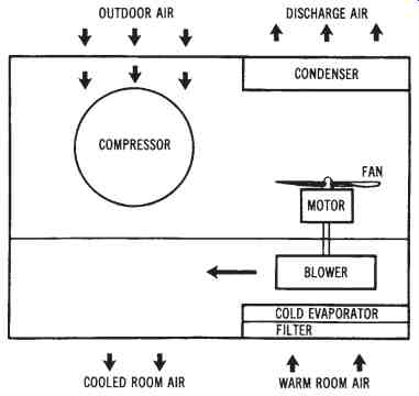 FIG.
8. A simplified diagram of a room air conditioning unit.
Electrically energized comfort heating systems are widely used to day to produce heat for commercial, industrial, and residential buildings. Electrical energy is readily available at nearly any building site, and it has a number of advantages over fuel-burning methods of producing heat. Ecologically, any fuel needed to produce electricity is burned or consumed at a power plant, which is usually located some distance from the building where it is being used. With this method of heating, there is less pollution than there would be if fuel were burned at each building.
Electric heat is also clean to use, easy to control, and highly efficient.
Electric heating is important today because of its high level of efficiency. Theoretically, when electrical energy is applied to a system, virtually all of it is transformed into heat energy. Essentially, this means that, when a specified amount of electricity is applied, it produces an equivalent Btu output. One thousand watts or 1 kW of electricity, when converted to heat, produces 3412 Btus of heat energy.
Heating can be achieved in a variety of ways through the use of electricity. Comfort heating systems contain an energy source, transmission path, control load device, and the possibility of one or more option al indicators. The primary difference between heat-pump and resistance electrical systems is in the production of heat energy. Resistance heating is accomplished by passing an electrical current through wires or conductors to the load device. By comparison, the heat pump operates by circulating a gas or liquid through pipes that connect an inside coil to an outside coil. Electricity is needed in both cases as an energy source to make the systems operational.
Resistance Heating in Buildings
When an electric current flows through a conductive material, it encounters a type of opposition called resistance. In most circuits this opposition is unavoidable, to some extent, because of the material of the conductor, its length, its cross-sectional area, and its temperature. The conductor wires of a heating system are purposely kept low in resistance to minimize heat production between the source and the load device.
Heavy-gauge insulated copper wire is used for this part of the system.
The load device of a resistance heating system is primarily responsible for the generation of heat energy. The amount of heat developed by the load depends upon the value of current that passes through the resistive element. Element resistance is purposely designed to be quite high compared to that of the connecting wires of the system. An alloy of nickel and chromium called Nichrome is commonly used for the heating elements.
Resistive elements may be placed under windows, or at strategic locations throughout the building. In this type of installation, the elements are enclosed in a housing that provides electrical safety and efficient use of the available heat. Air entering at the bottom of the unit circulates around the fins to gain heat, than exits at the top. Different configurations may be selected according to the method of circulation desired, unit length, and heat-density production.
Resistive elements are also used as a heat source in forced-air central heating systems. In this application, the element is mounted directly in the main airstream of the system. The number of elements selected for a particular installation is based upon the desired heat output production. Individual elements are generally positioned in a staggered configuration to provide uniform heat transfer and to eliminate hot spots. The element has spring-coil construction supported by ceramic insulators.
Units of this type provide an auxiliary source of heat when the outside temperature becomes quite cold. Air circulating around the element is warmed and forced into the duct network for distribution throughout the building.
Heat Pump Systems in Buildings
A heat pump is defined as a reversible air conditioning system that transfers heat either into or away from an area that is being conditioned.
When the outside temperature is warm, the heat pump takes indoor heat and moves it outside, thus acting as an air conditioning unit. Operation during cold weather causes it to take outdoor heat and move it indoors, functioning as a heating unit. Heating can be performed even during cold temperatures, because there is always a certain amount of heat in the out side air. At 0°F (-22°C), for example, the air will have approximately 89 percent of the heat that it has at 100°F (38°C). Even at subzero temperatures, it is possible to develop some heat from the outside air. However, it is more difficult to develop heat when the temperature drops below 20°F (-6°C). For installations that encounter temperatures colder than this, heat pumps are equipped with resistance heating coils to supplement the system.
A heat pump, like an air conditioner, consists of a compressor, an outdoor coil, an expansion device, and an indoor coil. The compressor is responsible for pumping a refrigerant between the indoor and outdoor coils. The refrigerant is alternately changed between liquid and gaseous states, depending upon its location in the system. Electric fans or blowers are used to force air across the respective coils, and to circulate cool or warm air throughout the building.
A majority of the heat pumps in operation today consist of indoor and outdoor units that are connected together by insulated pipes or tubes.
The indoor unit houses the supplemental electric heat elements, the blower and motor assembly, the electronic air cleaner, the humidifier, the control panel, and the indoor coil. The outdoor unit is covered with a heavy gauge steel cabinet that encloses the outdoor coil, the blower fan assembly, the compressor, the expansion device, and the cycle-reversing valve.
Both units are designed for maximum performance, high operational efficiency, and low electrical power consumption.
The Heating Cycle of a Heat Pump
If a unit air conditioner were turned around in a window during its operational cycle, it would be extracting heat from the outside air and pumping it into the building. This condition, which is the operational basis of the heat pump, is often called the reverse-flow air conditioner principle. The heat pump is essentially "turned around" from its cooling cycle by a special valve that reverses the flow of refrigerant through the system.
When the heating cycle occurs, the indoor coil, outdoor coil, and fans are reversed. The outdoor coil is now responsible for extracting heat from the outside air and passing it along the indoor coil, where it is released into the duct network for distribution.
During the heating cycle, any refrigerant that is circulating in the outside coil is changed into a low-temperature gas. It is purposely made to be substantially colder than the outside air. Since heat energy always moves from hot to cold, there is a transfer of heat from the outside air to the cold refrigerant. In a sense, we can say that the heat of the cold outside air is absorbed by the much colder refrigerant gas.
The compressor of the system is responsible for squeezing together the heat-laden gas that has passed through the outside coil. This action is designed to cause an increase in the pressure of the gas that is pumped to the indoor coil. As air is blown over the indoor coil, the high-pressure gas gives up its heat to the air. Warm air is then circulated through the duct network to the respective rooms of the system.
When the refrigerant gas of the indoor coil gives up its heat, it cools and condenses into a liquid. It is then pumped back to the outside coil by compressor action. Once again it is changed into a cool gaseous state and is applied to the outside coil to repeat the cycle. If the outside temperature drops too low, the refrigerant may not be able to collect enough heat to satisfy the system. When this occurs, electric-resistance heaters are energized to supplement the heating process. The place where electric heat is supplied to the system is called the balance point.
FIG. 9 shows an illustration of heat-pump operation during its heating cycle. At (1), the heat is absorbed from the cold outside air by the pressurized, low-temperature refrigerant circulating through the outside coil. As (2), the refrigerant is applied to the compressor and compressed into a high-temperature, high-pressure gas. At (3), the heated gas is transferred to the indoor coil and released as heat. At (4), warm air is circulated through the duct network. Note that the supplemental resistance heat element is placed in this part of the system. At (5), the refrigerant is returned to the compressor and then to an expansion device, where the liquid refrigerant is condensed and then returned to the outdoor coil. The cycle repeats itself from this point.
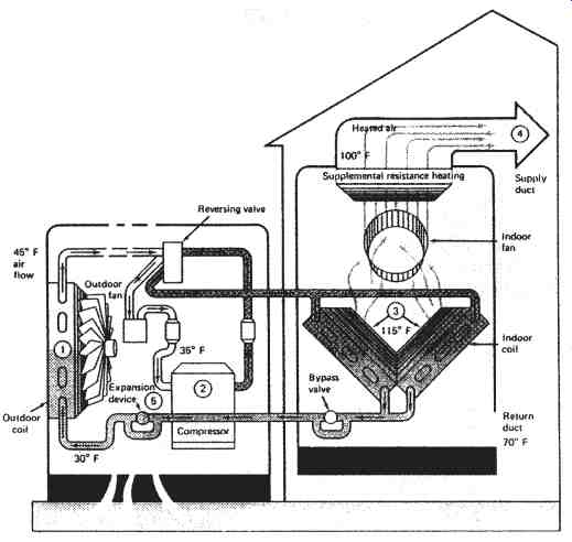
FIG. 9. Heating cycle operation
The Cooling Cycle of a Heat Pump
A heat pump is designed to respond as an air conditioning unit during the summer months. For this to occur, the reversing valve must be placed in the cooling-cycle position. In some systems this is accomplished by a manual changeover switch, whereas in others it is achieved automatically, according to the thermostat setting. The operating position of the valve simply directs the flow path of the refrigerant.
When the cooling cycle is placed in operation, it first causes the refrigerant to flow from the compressor into the indoor coil. During this part of the cycle the refrigerant is in a low-pressure gaseous state and is quite cool. As the circulation process continues, the indoor coil begins to absorb heat from the inside air of the building. Air passing over the indoor coil is cooled and circulated into the duct network for distribution throughout the building.
After leaving the indoor coil, the refrigerant must pass through the reversing valve and into the compressor. The compressor is responsible for increasing the pressure of the refrigerant and circulating it into the outdoor coil. At this point of the cycle, the refrigerant gives up its heat to the outside air, is cooled, and is changed into a liquid state. It then returns to the compressor, where it is pumped through an expansion device and returned to the indoor coil. The process then repeats itself.
FIG. 10 shows an illustration of the heat pump during its air conditioning cycle. At (1), heat is absorbed from the inside air and cool air is transferred into the building. At (2), the pressure of the heat-laden refrigerant is increased by the compressor and cycled into the outside coil for transfer to the air. At (3), cool, dehumidified air is circulated through the duct network as a result of passing through the cooled indoor coil. At (4), the refrigerant condenses back into a liquid as it circulates through the outdoor coil. At (5), the liquid refrigerant flows through the compressor and expansion device, where it is vaporized and returned to the indoor coil to complete the cycle.