AMAZON multi-meters discounts AMAZON oscilloscope discounts
The electrical load devices that are used in industry, in our homes, and in commercial buildings are very important parts of electrical power systems. The load of any system performs a function that involves power conversion. A load converts one form of energy to another form. An electrical load converts electrical energy to some other form of energy, such as heat, light, or mechanical energy. Electrical loads may be classified according to the function that they perform (lighting, heating, mechanical), or by the electrical characteristics that they exhibit (resistive, inductive, capacitive).
TERMINOLOGY
This Section deals with fundamentals of electrical loads. After studying this Section, you should have an understanding of the following terms:
- Load
- Resistive Load
- Capacitive Load
- Inductive Load
- Load (Demand) Factor
- Power Factor
- Power Factor Correction
- True Power
- Apparent Power
- Reactive Power
- Static Capacitor
- Synchronous Capacitor
- Balanced Three-phase Load
- Unbalanced Three-phase Load
- Line Voltage (VL)
- Phase Voltage (VP)
- Line Current (IL)
- Phase Current (IP)
- Power per Phase (PP)
- Total Three-phase Power (PT)
LOAD CHARACTERISTICS
In order to plan for power system load requirements, we must understand the electrical characteristics of all the loads connected to the power system. The types of power supplies and distribution systems that a building uses are determined by the load characteristics. All loads may be considered as either resistive, inductive, capacitive, or a combination of these. We should be aware of the effects that various types of loads will have on the power system. The nature of AC results in certain specific electrical circuit properties.
You should review that portion of Section 2 that deals with resistive, inductive, and capacitive effects in an electrical circuit. One primary factor that affects the electrical power system is the presence of inductive loads.
These are mainly electric motors. To counteract the inductive effects, utility companies use power factor corrective capacitors as part of the power system design. Capacitor units are located at substations to improve the power factor of the system. The inductive effect, therefore, increases the cost of a power system and reduces the actual amount of power that is converted to another form of energy.
Load (Demand) Factor
One electrical load relationship that is important to understand is the load (or demand) factor. Load factor expresses the ratio between the average power requirement and the peak power requirement, or:
average demand (kW)
load demand factor = ---------- peak demand (kW)
Sample Problem:
Given: a factory has a peak demand of 12 MW and an average power demand of 9.86 MX.
Find: the load (demand) factor for the factory.
Solution:
Avg. Demand
DF = ------- Peak Demand
9.86 MW = ---- 12MW
DF = 0.82
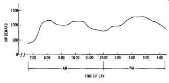
FIG. 1. Load profile for an industrial plant.
The average demand of an industry or commercial building is the average electrical power used over a specific time period. The peak demand is the maximum amount of power (kW) used during that time period. The load profile shown in FIG. 1 shows a typical industrial demand-versus-time curve for a working day. Demand peaks that far exceed the average demand cause a decrease in the load factor ratio. Low load factors result in an additional billing charge by the utility company.
Utility companies must design power distribution systems that take peak demand time into account, and ensure that their generating capacity will be able to meet this peak power demand. Therefore, it is inefficient electrical design for an industry to operate at a low-load factor, since this represents a significant difference between peak-power demand and aver age-power demand. Every industry should attempt to raise its load factor to the maximum level it can. By minimizing the peak demands of industrial plants, power demand control systems and procedures can help increase the efficiency of our nation's electrical power systems.
Be careful not to confuse the load factor of a power system with the power factor. The power factor is the ratio of power converted (true power), to the power delivered to a system (apparent power). If necessary, you should review power factor.
Most industries use a large number of electric motors; therefore, industrial plants represent highly inductive loads. This means that industrial power systems operate at a power factor of less than unity (1.0). However, it is undesirable for an industry to operate at a low-power factor, since the electrical power system will have to supply more power to the industry than is actually used.
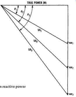
FIG. 2. Effect of increases in reactive power (VAR) on apparent power
(VA)
A given value of volt-amperes (voltage × current) is supplied to an industry by the electrical power system. If the power factor (pf) of the industry is low, the current must be higher, since the power converted by the total industrial load equals VA × pf. The value of the power factor de creases as the reactive power (unused power) drawn by the industry in creases. This is shown in FIG. 2. We will assume a constant value of true power, in order to see the effect of increases in reactive power drawn by a load. The smallest reactive power shown (VAR1) results in the volt ampere value of VA1. As reactive power is increased, as shown by the VAR2 and VAR3 values, more volt-amperes (VA2 and VA3) must be drawn from the source. This is true since the voltage component of the supplied volt-amperes remains constant. This example represents the same effect as a decrease in the power factor, since pf = W/VA, and, as VA increases, the pf will decrease if W remains constant.
Utility companies usually charge industries for operating at power factors below a specified level. It is desirable for industries to "correct" their power factor to avoid such charges and to make more economical use of electrical energy. Two methods may be used to cause the power factor to increase: (1) power-factor-corrective capacitors, and (2) three phase synchronous motors. Since the effect of capacitive reactance is opposite to that of inductive reactance, their reactive effects will counteract one another. Either power-factor-corrective capacitors, or three-phase synchronous motors, may be used to add the effect of capacitance to an AC power line.
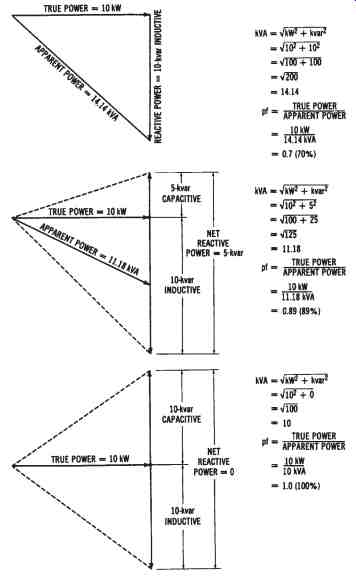
FIG. 3. Illustration of the effect of capacitive reactance on an inductive
circuit: (A) Reactive power = 10 kVAR inductive, (B) Reactive power = 10
kVAR inductive, and 5 kVAR capacitive, (C) Reactive power = 10 kVAR inductive,
and 10 kVAR capacitive
An example of power factor correction is shown in FIG. 3.
We will assume from the example that both true power and inductive reactive power remain constant at values of 10 kW and 10 kVAR. In FIG. 3A, the formulas show that the power factor equals 70 per cent. However, if 5-kVAR capacitive reactive power is introduced into the electrical power system, the net reactive power becomes 5 kVAR (10-kVAR inductive minus 5-kVAR capacitive), as shown in Figure 11 3B. With the addition of 5-kVAR capacitive to the system, the power factor is increased to 89 percent. Now, in FIG. 3C, if 10-kVAR capacitive is added to the power system, the total reactive power (kVAR) becomes zero. The true power is now equal to the apparent power; therefore, the power factor is 1.0, or 100 percent, which is characteristic of a purely resistive circuit. The effect of the increased capacitive reactive power in the system is to increase or "correct" the power factor and, thus, to reduce the current drawn from the power distribution lines that supply the loads. In many cases, it is beneficial for industries to invest in either power-factor-corrective capacitors, or three-phase synchronous motors, to correct their power factor. Calculations may be simplified by using the chart of TABLE 1.
Utility companies also attempt to correct the power factor of the power distribution system. A certain quantity of inductance is present in most of the power distribution system, including the generator windings, the transformer windings, and the power lines. To counteract the inductive effects, utilities use power-factor-corrective capacitors.
Capacitors for Power Factor Correction
Static capacitors are used for power factor correction in the system.
They are constructed similarly to the smaller capacitors used in electrical equipment, which have metal-foil plates separated by paper insulation.
Ordinarily, static capacitors are housed in metal tanks, so that the plates can be immersed in an insulating oil to improve high-voltage operation.
The usual operating voltages of static capacitors are from 230 volts to 13.8 kilovolts. These units are connected in parallel with power lines, usually at the industrial plants, to increase the system power factor. Their primary disadvantage is that their capacitance cannot be adjusted to compensate for changing power factors.
Power factor correction can also be accomplished by using synchronous capacitors connected across the power lines. (Three-phase synchronous motors are also called synchronous capacitors; see Section 14 for a discussion of three-phase synchronous motors.) The advantage of synchronous capacitors over static capacitors is that their capacitive effect can be adjusted as the system power factor increases or decreases. The capacitive effect of a synchronous capacitor is easily changed by varying the DC excitation voltage applied to the rotor of the machine. Industries considering the installation of either static or synchronous capacitors should first compare the initial equipment cost and the operating cost against the savings brought about by an increased system power factor.
THREE-PHASE LOAD CHARACTERISTICS
In another section, single-phase circuit fundamentals were discussed.
However, the major type of load in electrical power systems is the three phase load. Therefore, you should become familiar with the characteristics of three-phase loads.
TABLE 1. Kilowatt (kW) Multipliers for Determining Capacitor Kilovars (kVAR)
Balanced Three-phase Loads
A balanced three-phase load means that the resistance or impedances connected across each phase of the system are equal. Three-phase motors are one type of balanced load. The following relationships exist in a balanced, three-phase delta system. The line voltages (VL) are equal to the phase voltages (VP). The line currents (IL) are equal to the phase currents (IP) multiplied by 1.73. Thus:
VL = VP
IL = IP × 1.73
For a balanced three-phase wye system, the method used to find the voltages and currents is similar. The voltage across the AC lines (VL) is equal to the square root of 3 (1.73) multiplied by the voltage across the phase windings (VP), or VL = VP × 1.73.
The line currents (IL) are equal to the phase currents (IP), or IL = IP
The power developed in each phase (PP), for either a wye or a delta circuit, is expressed as:
PP = VP x IP × pf where:
pf is the power factor (phase angle between voltage and current) of the load.
The total power developed by all three phases of a three-phase generator (PT) is expressed as:
PT
=3 × PP
= 3 × VP × IP × pf
= 1.73 × VL × IL × pf
As an example, we can calculate the phase current (IP), line current (IL), and total power (PT) for a 240-volt, three-phase, delta-connected system with 1000-watt load resistances connected across each power line. The phase current is:
PP
IP = -- VP
1000 watts
= ----- 240 volts
= 4.167 amperes
The line current is calculated as:
IL = IP × 1.73
= 4.167 × 1.73
= 7.21 amperes
Thus, the total power is determined as:
PT
= 3 × PP
= 3 × 1000 watts
= 3000 watts
Another way to calculate the total power is:
PT = 1.73 × VL × IL x pf
= 1.73 × 240 volts × 7.21 amperes × 1
= 2993.59 watts
(Note that your answer depends upon the number of decimal places to which you carry your calculations. Round off IL at 7.2 amperes, and your answer for the last calculation is 2989.44 watts, instead of 2993.59 watts.)
The following is an example of the power calculation for a three phase wye system. For the problem, "find the line current (IL) and power per phase (PP) of a balanced, 20,000-watt, 277/480-volt, three-phase wye system operating at a 0.75 power factor," we use the formula:
PT = VL × IL × 1.73 × pf
Transposing and substituting, we have:
PT
IL = ------ VL × PT × pf
20,000 watts
= ---------- 480 volts × 1.73 × 0.75
= 32.11 amperes
Then, for the power per phase (PP), divide the 20,000 watts of the sys tem by 3 (the number of phases), for a value of 6,666.7 watts (6.66 kW).
Unbalanced Three-phase Loads
Often, three-phase systems are used to supply power to both three phase and single-phase loads. If three, identical, single-phase loads were connected across each set of power lines, the three-phase system would still be balanced. However, this situation is usually difficult to accomplish, particularly when the loads are lights. Unbalanced loads exist when the individual power lines supply loads that are not of equal resistances or impedances.
The total power converted by the loads of an unbalanced system must be calculated by looking at each phase individually. Total power of a three-phase unbalanced system is:
PT = PP-A + PP-B + PP-C
... where the power-per-phase (PP) values are added. Power per phase is found in the same way as when dealing with balanced loads:
PP = VP × IP
× power factor
The current flow in each phase may be found if we know the power per phase and the phase voltage of the system. The phase currents are found in the following manner:
Sample Problem:
Given: the following 120-volt single-phase loads are connected to a 120/208-volt wye system. Phase A has 2000 watts at a 0.75 power factor, Phase B has 1000 watts at a 0.85 power factor, and Phase C has 3000 watts at a 1.0 power factor.
Find: the total power of the three-phase system, and the current flow through each line.
Solution: To find the phase currents, use the formula PP = VP × IP × power factor, and transpose. Thus, we have IP = PP/VP × pf. Substitution of the values for each leg of the system gives us:
1. PP-A *IP-A = ---- VP × pf
2000 watts
= -------- 120 volts × 0.75
= 22.22 amperes
*This notation means phase current (IP) of "A" power line.
2. PP-B
*IP-B = ---- VP × pf
1000 watts
= -------- 120 volts × 0.85
= 9.8 amperes
3. PP-C
*IP-C = ---- VP × pf
3000 watts
= -------- 120 volts × 1.0
= 25.0 amperes
To determine the total power, use the total power formula for a three phase unbalanced system, which was just given:
PT = PP-A + PP-B + PP-C
= 2000 + 1000 + 3000
= 6000 watts (6 kW)
