AMAZON multi-meters discounts AMAZON oscilloscope discounts
Electrical lighting systems are designed to create a comfortable and safe home or working environment. There are several types of lighting systems in use today. Among the most popular are incandescent, fluorescent, and vapor lights, as well as several special-purpose types of lighting.
Lighting systems are one type of electrical load.
The three types of lighting systems discussed in this Section constitute most of the lighting loads placed on electrical power systems.
Incandescent, fluorescent, and vapor lights are used for many lighting applications. However, there are a few other specialized types of lighting that are also used. These include zirconium and xenon arc lights, glow lights, black lights, and infrared lights. The planning involved in obtaining proper lighting is quite complex and may involve several types of lights.
TERMINOLOGY
This section deals with lighting systems. After studying this section, you should have an understanding of the following terms:
- Visible Light
- Electromagnetic Spectrum
- Candlepower
- Lumen
- Footcandle
- Reflection Factor Foot-lambert
- Street Lighting
- Incandescent Lighting
- Fluorescent Lighting
- Vapor Lighting
- Lighting Circuits
- Three-Way Switch
- Four-Way Switch
- Lighting Branch Circuits
- Lighting Fixture
- Luminaire
- Coefficient of Utilization (CU)
- Room Ratio
- Depreciation Factor (DF)
- Light Output
CHARACTERISTICS OF LIGHT
In order to better understand lighting systems, you should know something about the basic characteristics of light. Light is a visible form of radiation that is actually a narrow band of frequencies along the vast electromagnetic spectrum. The electromagnetic spectrum, shown in FIG. 1, includes bands of frequencies for radio, television, radar, infrared radiation, visible light, ultraviolet light, x-rays, gamma rays, and various other frequencies. The different types of radiation, such as light, heat, radio waves, and x-rays, differ only with respect to their frequencies, or wavelengths.
The human eye responds to electromagnetic waves in the visible light band of frequencies. Each color of light has a different frequency, or wave length. In order of increasing frequency (or decreasing wavelengths), the colors are red, orange, yellow, green, blue, indigo, and violet. The wave lengths of visible light are in the 400-millimicrometer (violet) to 700-millimicrometer (red) range. A micrometer (mm), which is also called a mi cron (µm), is one millionth of a meter, and a nanometer (nm) is 1 × 10⁻³ micrometer. Angstrom units (Å) are also used for light measurement. An angstrom unit is one-tenth of a nanometer. In order to avoid confusion, use the conversion chart given in TABLE 1.
Visible light ranges from 4000 Å to 7000 Å. The response of the human eye to visible light exhibits a frequency selective characteristic, as shown in FIG. 2. The greatest sensitivity is near 5500 Å. The poorest sensitivity is around 4000 Å on the lower wavelengths, and 7000 Å on the higher wavelengths. Our eyes perceive various degrees of brightness, de pending on their response to the wavelengths of light. The normal human eye cannot see a wavelength of less than 4000 Å (<400 nm), or more than 7000Å(>700 nm).
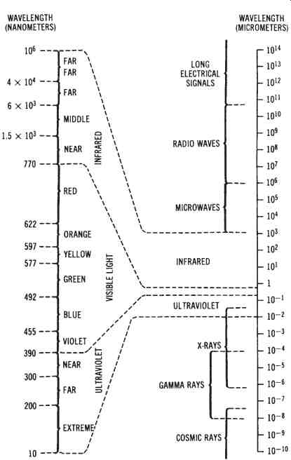
FIG. 1. The electromagnetic spectrum
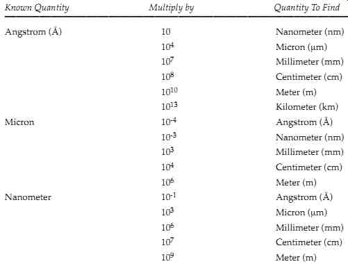
TABLE 1. Conversion Chart for Electromagnetic Wavelengths: Known Quantity
Multiply by Quantity To Find
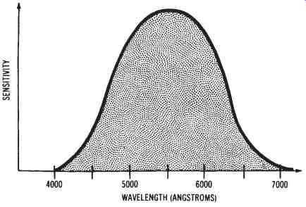
FIG. 2. Response of the human eye to visible light
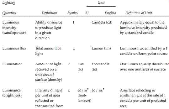
When dealing with light, there are several characteristic terms that you should understand. The unit of luminous intensity is a standard light source called a candela or candlepower. The intensity of light is expressed in one of these units. The amount of light falling on a unit surface, all points of which are a unit distance from a uniform light source of one candela, is one lumen. The illumination of a surface is the number of lumens falling on it per unit area. The unit of illumination is the lux (lumens per square meter) or footcandle (lumens per square foot).
We see only light that is reflected. Reflected light is measured in candelas per square meter of surface (or foot lamberts). The reflection factor is the percent of light reflected from a surface expressed as a decimal.
Therefore, the light reflected from a surface is equal to the illumination of the surface times the reflection factor. The brightness of a surface that reflects one lumen per square foot is one foot-lambert.
Units of light measurement are given in both English and International Systems of Units (metric) units. This can become somewhat confusing.
TABLE 2 summarizes the most common terms used for light measurement.
==========
---- Lighting
Quantity
----- Luminous A intensity t (candlepower) i
Luminous flux T
Illumination A
Luminance (brightness)
---
Definition of Unit
Approximately equal to the luminous intensity produced by a standard candle
Luminous flux emitted by a 1 candela uniform point source
One lumen equally distributed over one unit area of surface
A surface reflecting or emitting light at the rate of 1 candela per unit of projected area.
===========
Incandescent Lighting
Incandescent lighting is a widely used method of lighting, used for many different applications. The construction of an incandescent lamp is shown in FIG. 3. This lamp is simple to install and maintain. The initial cost is low; however, incandescent lamps have a relatively low efficiency and a short life span.
Incandescent lamps usually have a thin tungsten filament, which is in the shape of a coiled wire. This filament is connected through the lamp base to a volt age source (usually 120 volts AC). When an electric current is passed through the filament, the temperature of the filament rises to between 3000° to 5000° Fahrenheit. At this tempera ture range, the tungsten produces a high-intensity white light. When the incandescent lamp is manufactured, the air is removed from the glass envelope to prevent the filament from burning; also, an inert gas is added.
Incandescent lamps are purely resistive devices, and thus have a power factor of 1.0. As they deteriorate, their light output is reduced. Typically, at the time that an incandescent lamp bums out, its light out put is less than 85 percent of its original output. A decrease in the voltage of the power system also reduces the light output.
A 1 percent decrease in voltage will cause a 3 percent decrease in light output.
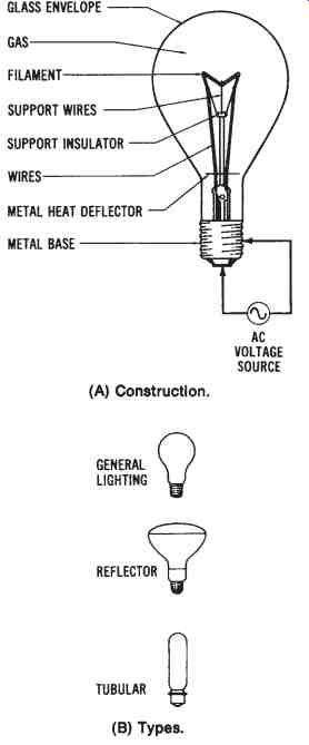
FIG. 3. The incandescent lamp: (A) Construction, (B) Types
Fluorescent Lighting
Fluorescent lighting is used extensively today, particularly in industrial and commercial buildings. Fluorescent lamps are tubular bulbs with a filament at each end. There is no electrical connection between the two filaments. The operating principle of the fluorescent lamp is shown in FIG. 4. The tube is filled with mercury vapor; thus, when an electrical current flows through the two filaments, a continuous arc is formed between them by the mercury vapor. High-velocity electrons passing between the filaments collide with the mercury atoms, producing an ultra violet radiation. The inside of the tube has a phosphor coating that reacts with the ultraviolet radiation to produce visible light.

FIG. 4. Operating principle of a fluorescent lamp
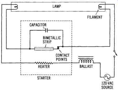
FIG. 5. Circuit diagram of a fluorescent lamp
One circuit for a fluorescent light is shown in FIG. 5. Note that a thermal starter, which is basically a bimetallic strip and a heater, is connected in series with the filaments. The bimetallic strip remains closed long enough for the filaments to heat and vaporize the mercury in the tube. The bimetallic switch will then bend and open as the result of the heat produced by current flow through the heater. The filament circuit is now opened. A capacitor is connected across the bimetallic switch to re duce contact sparking. Once the contacts of the starter open, a high volt age momentarily occurs between the filaments of the lamp, because of the action of the inductive ballast coil. The ballast coil has many turns of small-diameter wire, and, thus, it produces a high, counter-electromotive force when the contacts of the starter separate. This effect is sometimes called "inductive kickback." The high voltage across the filaments causes the mercury to ionize and initiates a flow of current through the tube.
There are several other methods used to start fluorescent lights; however, this method illustrates the basic operating principle.
Fluorescent lights produce more light per watt than incandescent lights; therefore, they are cheaper to operate. Since the illumination is produced by a long tube, there is also less glare. The light produced by fluorescent bulbs is very similar to natural daylight. The light is whiter, and the operating temperature is much lower with fluorescent than with in candescent lights. Various sizes and shapes of fluorescent lights are avail able. The bulb sizes are expressed in eighths of an inch, with the common sizes being T-12 and T-8. (A T-12 bulb is 1-1/2 inches.) Common lengths are 24, 48, 72, and 96 inches.
Vapor Lighting
Another popular form of lighting is the vapor type. The mercury-vapor light is one of the most common types of vapor light. Another common type is the sodium-vapor light. These lights are filled with a gas that produces a characteristic color. For instance, mercury vapor produces a greenish-blue light, and argon a bluish white light. Gases may be mixed to produce various color combinations for vapor lighting. This is often done with signs used for advertising.
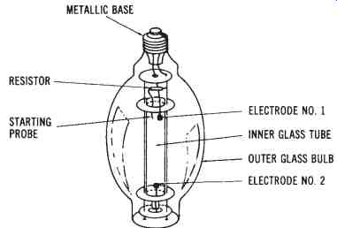
A mercury-vapor lamp is shown in FIG. 6. It consists of two tubes with an arc tube placed inside an outer bulb. The inner tube contains mercury. When a voltage is applied between the starting probe and an electrode, an arc is started between them. The arc current is limited by a series resistor; however, the current is sufficient to cause the mercury in the inner tube to ionize. Once the mercury has ionized, an intense greenish-blue light is produced. Mercury-vapor lights are compact, long lasting, and easy to maintain. They are used to provide a high-intensity light output. At low voltages, mercury is slow to vaporize, so these lamps require a long starting time (sometimes 4 to 8 minutes). Mercury-vapor lights can also be used for outdoor lighting.
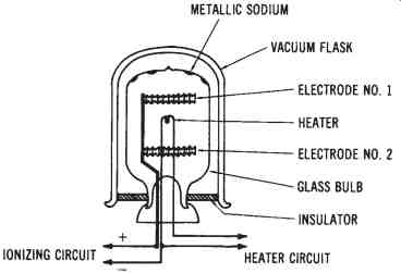
The sodium-vapor light, shown in FIG. 7, is popular for outdoor lighting and for highway lighting. This lamp contains some low-pressure neon gas and some sodium. When an electric current is passed through the heater, electrons are given off. The ionizing circuit causes a positive charge to be placed on the electrodes. As electrons pass from the heater to the positive electrodes, the neon gas is ionized. The ionization of the neon gas produces enough heat to cause the sodium to ionize. A yellowish light is produced by the sodium vapor. The sodium-vapor light can produce about three times the candlepower per watt as an incandescent light.
Another type of vapor lamp is called a metal halide type. This light source is a high intensity mercury-vapor lamp in which metallic substances, called metal halides, are added to the bulb. The addition of these sub stances improves the efficacy of the lamps. The efficacy of a metal halide lamp is typically 75 lumens/watt, compared to approximately 50 lumens/ watt for mercury-vapor lamps.
Another type of vapor lamp is the high-pressure sodium (HPS) lamp. Sodium is the primary element used to fill the lamp's tube when it is manufactured. These lamps have very high efficacies-approximately 110 lumens/watt.
Street Lighting
The lighting systems of today are highly reliable, compared to the systems that were installed many years ago. Earlier systems were turned on and off either manually, or by timing devices that were regulated by the time of day, rather than by the natural light intensity. Some were con trolled by electrical impulses that were transmitted on the power lines.
Now, most systems are controlled by automatic photoelectric circuits. The lights that are now used to illuminate streets and highways have photo electric controls. They operate during periods of darkness and are automatically turned off when natural light is present. These street lights are usually connected to existing 120/240-volt power distribution systems.
There are many types of street lights in use. The earliest types of electric street lights used were 200- to 1000-watt incandescent lamps. Now, mercury-vapor and sodium-vapor lamps are the primary types used. (Mercury lamps produce a white light, and sodium lamps have a yellowish color.) Several different lamp designs and mounting fixture designs are used.
Several years ago, street lights were converted from incandescent lamps to mercury-vapor lamps. Now the trend in street lighting seems to be toward the use of sodium-vapor lights, and several areas of the country have converted to the use of sodium-vapor lamps. Sodium-vapor lights produce more illumination than a similar mercury-vapor light. They also require less electrical power to produce a specific amount of illumination.
Thus, the ability of sodium-vapor lights to deliver more light with less power consumption makes them more economically attractive than mercury-vapor lights.
Comparison of Light Sources
The purpose of a light source is to convert electrical energy into light energy. A measure of how well this is done is called efficacy. Efficacy is the lumens of light produced per watt of electrical power converted. A comparison of some different types of light sources is shown below:
Efficacy | Lamp Type (Lumens/watt)
200 Watt incandescent lamp 20
400 Watt mercury lamp 50
40 Watt fluorescent lamp 70
400 Watt metal halide lamp 75
400 Watt high-pressure sodium lamp 110
ELECTRICAL LIGHTING CIRCUITS
There are several types of electrical circuits that are used for electrical lighting control. We will study some of the circuits used for incandescent and fluorescent lighting systems. Electrical lighting circuits for different areas of a building must be wired properly. Some lighting fixtures are controlled from one point by one switch, while other fixtures may be controlled from two or more points by a switch at each point.
Incandescent lighting circuits are a typical type of branch circuit. The most common type of incandescent lighting circuit is a 120-volt branch that extends from a power distribution panel to a light fixture or fixtures in some other area of a building. The path for the electrical distribution is controlled by one or more switches that are usually placed in small metal or plastic enclosures inside a wall. These switches are then covered by rectangular plastic plates to prevent possible shock hazards.
Switches are always placed in a wiring circuit so that they can open or close a hot wire. This hot wire distributes electrical power to the lighting fixtures that the switches control. These switches are referred to as "T rated" switches. They are designed to handle the high, instantaneous cur rent drawn by lights when they are turned on. A switch that accomplishes control from a single location is a simple, single-pole, single-throw (spst) switch, such as that shown in FIG. 8. A pictorial view of the same circuit is shown in FIG. 9.
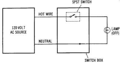
FIG. 8. Schematic diagram for the control of a light from one location
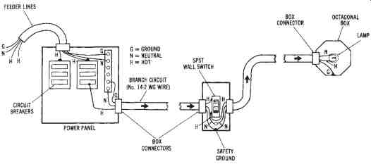
FIG. 9. Pictorial view of the circuit shown in FIG. 8
Control from two locations, such as near the kitchen door and inside the garage door, is accomplished by two 3-way switches. This circuit is shown in FIG. 10A, while FIG. 11 presents a pictorial view of the same circuit. When control of a lighting fixture from more than two points is desired, two 3-way switches and one or more 4-way switches are used.
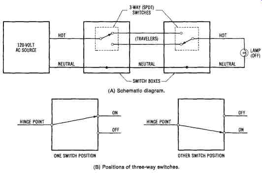
FIG. 10. Circuit for controlling a light from two locations: (A) Schematic
diagram, (B) Positions of three-way switches
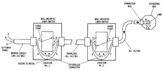
FIG. 11. Pictorial view of the circuit of FIG. 10 (A)
For instance, control of one light from five points could be accomplished by using a combination of two 3-way switches and three 4-way switches.
FIG. 12 and 13 show a circuit for controlling a light from three locations. The 3-way switches are always connected to the power panel and to the light fixture, with the 4-way switch between them. The use of 3-way and 4-way switch combinations makes it possible to achieve control of a light from any number of points.
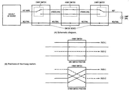
FIG. 12. Circuit for controlling a light from three locations: (A) Schematic
diagram, (B) Positions of the four-way switch.
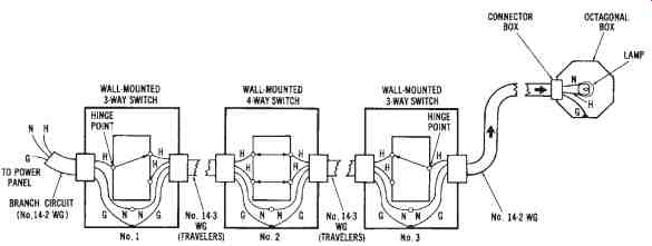
FIG. 13. Pictorial view of the circuit shown in FIG. 12(A).
Each lighting-control circuit requires an entirely different type of switching combination to adequately accomplish control of a lighting fixture. These circuits are usually wired into buildings during construction, in order to provide the type of lighting control desired for each room. You should study the diagrams of FIGs 8 through 13 to fully under stand how these lighting circuits operate.
BRANCH CIRCUIT DESIGN
The design of lighting branch circuits involves the calculation of the maximum current that can be drawn by the lights that are connected to the branch circuit. Many times, particularly in homes, a lighting branch circuit also has duplex receptacles for portable appliances. This makes the exact current calculation more difficult, since not all the lights or the appliances will be in use at the same time.
The National Electrical Code (NEC) specifies that there should be at least one branch circuit for each 500 square feet of lighting area. The NEC further specifies a minimum requirement for lighting for various types of buildings. TABLE 3 lists the number of watts of light per square foot required in some buildings.
The solution of a typical branch circuit lighting problem follows.
---------
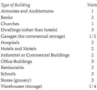
TABLE 3. Building Lighting Requirements in Wattage per Square Foot
Type of Building | Watts
- Armories and Auditoriums 1
- Banks 2
- Churches 1
- Dwellings (other than hotels) 3
- Garages (for commercial storage) 1/2
- Hospitals 2
- Hotels and Motels 2
- Industrial or Commercial Buildings 2
- Office Buildings 5
- Restaurants 2
- Schools 3
- Stores (grocery) 3
- Warehouses (storage) 1/4
-----------------
Sample Problem:
Given: a room in a commercial building is 70 feet × 120 feet (21.34 × 36.58 meters). It will use 125 fluorescent lighting units that draw 3 amperes each. Also, 20-ampere branch circuits will be used. The power factor of the units is 0.75. The operating voltage is 120 volts.
Find: the minimum number of branch circuits needed, and the total power requirement for the lighting units.
Solution for the branch circuits:
1. Find the number of units that should be installed on each branch circuit.
branch current units = ------- load current
20 amperes
= ----- 3 amperes
= 6.67 units (round off at 6)
2. Find the number of branch circuits needed.
lighting units circuits = -------------- No. units per branch circuit
125
= -- 6
= 20.8 (round up to 21)
Twenty-one 20-ampere branch circuits will be needed.
Solution for total power:
1. Find the total current drawn by the lights.
I = 125 units × 3 amperes
= 375 amperes
2. Calculate the total power.
p = V × I × pf
= 120 × 375 × 0.75
= 33,750 watts (33.75 kW)
An even more common type of branch circuit lighting problem is given in the following discussion. This problem begins with the minimum number of lights required in a room. The number of branch circuits that are required must be determined.
Sample Problem:
Given: a large room in an industrial building needs to have 40,000 watts of incandescent lighting. It is decided that 120-volt 20-ampere branch circuits will be used. The lights will use 200-watt bulbs.
Find: the number of branch circuits required for the lighting.
Solution:
1. Find the amount of current each lamp will draw.
P
I = -- V
200 watts
= ----- 120 volts
= 1.67 amperes
2. Find the maximum number of lamps in each branch circuit.
amperage of circuit
lamps = ---------- amperage of lamps
20 amperes
= ----- 1.67 amperes
= 11.97 (round down to 11)
3. Find the total number of bulbs (lamps needed.
wattage of room
bulb required = --------- wattage of bulbs
40,000 watts
= ------ 200 watts
= 200 bulbs required
4. Find the minimum number of branch circuits needed.
total bulbs required
branch circuits = ------------- number of bulbs per circuit
200
= -- 11
= 18.18 (round up to 19)
Nineteen branch circuits will be needed.
It should be pointed out that, in these problems, we determined the minimum number of branch circuits. But room for flexibility should be provided for each branch circuit. This can be done by designing the circuit to handle only 16 amperes (80 percent) rather than 20 amperes. Also, room should be provided on the power distribution panel to allow for connecting some additional lighting branch circuits. This will allow additional loads to be connected at a later time.
LIGHTING FIXTURE DESIGN
Lighting fixtures are the devices that are used to hold lamps in place.
They are commonly referred to as luminaires. Luminaires are used to efficiently transfer light from its source to a work surface. The proper de sign of luminaires allows a more efficient transfer of light. It is important to keep in mind that light intensity varies inversely as the square of the distance from the light source. Thus, if the distance is doubled, the light intensity will be reduced four times.
Many factors must be considered in determining the amount of light that is transferred from a light bulb to a work surface. Some light is absorbed by the walls and by the light fixture itself; thus, not all light is efficiently transferred. The manufacturers of lighting systems develop charts that are used to predict the amount of light that will be transferred to a work surface. These charts take into consideration the necessary variables for making a prediction of the quantity of light falling onto a surface.
Each luminaire has a rating, which is referred to as its coefficient of utilization. The coefficient of utilization is a factor that expresses the percentage of light output that will be transferred from a lamp to a work area.
The coefficient of a luminaire is determined by laboratory tests made by the manufacturer. These co-efficiency charts also take into consideration the light absorption characteristics of walls, ceilings, and floors, when the coefficient of utilization of a luminaire is to be determined.
Another factor used for determining the coefficient of utilization is the room ratio. Room ratio is very simply determined by the formula:
W × L
room ratio = ----- H (W + L) where:
W = the room width in feet,
L = the room length in feet, and
H = the distance in feet from the light source to the work surface.
Note: Work surfaces are considered to be 2.5 feet from the floor, unless otherwise specified.
FACTORS IN DETERMINING LIGHT OUTPUT
There are several other factors that must be considered in order to determine the amount of light transferred from a light source to a work surface. We know, for instance, that the age of a lamp has an effect on its light output. Lamp manufacturers determine a depreciation factor or maintenance factor for luminaires. This factor expresses the percentage of light output available from a light source. A depreciation factor of 0.75 means that in the daily use of a light source, only 75 percent of the actual light output is available for transfer to the work surface. The depreciation factor is an average value. It takes into consideration the reduction of light output with age, and the accumulation of dust and dirt on the luminaires.
Some collect dust more easily than others.
The following problem shows the effect of the coefficient of utilization (CD) and the depreciation factor (OF) on the light output transferred to a work surface.
Sample Problem:
Given: a lighting system for a building has 16 luminaries. Each luminaire has two fluorescent lamps. Each lamp has a light output of 3000 lumens. The CD and OF found in the chart developed by the manufacturer are 0.45 and 0.90, respectively.
Find: the total light output from the lighting system.
Solution:
1. Find the total light output from the lamps.
3000 lumens per lamp × 16 luminaires × 2 lamps per luminaire = 96,000 lumens
2. Find the total light output:
light output = total lumens × CD × DF
= 96,000 × 0.45 × 0.90
= 38,880 lumens
The distribution of light output onto work surfaces must also be considered. The CD and the DF are used to find the total light output of a lighting system. A greater light output is required for larger areas. The light output to a work surface is expressed as lumens per square foot, or footcandles. A light meter is used to measure the quantity of light that reaches a surface.
The following two formulas are useful for finding the required lumens for a work area, or the light output available from a particular lighting system:
desired footcandles × room area in ft.
total lumens = ----------------- CD × DF and
total lumens × CD × DF
footcandles available = ------------- room area in feet Sample Problem:
Given: a lighting system with 12,000 total lumen output, luminaire CD = 0.83 and DF = 0.85, is installed in a 600 sq. ft. room.
Find: the footcandles of light available on the work surface.
Solution:
lumens × CD × DF
FC = -------- room area
12,000 × 0.83 × 0.85
= --------- 600
FC = 14.11 footcandles
Considerations for Electrical Lighting Loads
Incandescent lamps produce light by the passage of electrical cur rent through a tungsten filament. The electrical current heats the filament to the point of incandescence, which causes the lamp to produce light. The primary advantage of incandescent lights is their low initial cost. However, they have a very low efficacy (lumen/watt) rating. They also have a very high operating temperature and a short life expectancy.
Incandescent lights are usually not good choices of light sources for commercial, industrial, or outdoor lighting applications; their primary applications are for residential use.
Fluorescent light sources have a higher efficacy (lumens/watt) than incandescent lights. They have a much longer life, and lower brightness and operating temperature. Fluorescent lights are used for residential (120-volt applications) and for general-purpose commercial and industrial lighting (120-volt and 277-volt systems). Disadvantages of fluorescent lights include the necessity for a ballast and a rather large luminaire. They also have a higher initial cost than incandescent lamps. It is estimated that fluorescent light sources provide approximately 70 percent of the lighting in the United States.
Vapor light sources also have very good efficacy ratings and long life expectancies. They have a high light output for their compact size.
They are typically used for industrial, commercial, and outdoor applications, since they can be operated economically on higher-voltage systems.
The initial cost of vapor lights is high, they require a ballast, and they are a very bright light source. Their very high efficacy ratings have led to in creased use of vapor light sources.
