AMAZON multi-meters discounts AMAZON oscilloscope discounts
Another broad category of electrical loads includes those devices that convert electrical energy into mechanical energy. Electric motors fall into this category of load devices. They are mechanical power-conversion systems. There are many types of motors used today. The electrical motor load is the major power-consuming load of electrical power systems.
Motors of various sizes are used for purposes that range from large industrial machine operation, to operating power blenders and mixers in the home.
TERMINOLOGY
This section deals with mechanical systems. After studying this section, you should have an understanding of the following terms:
- Motor
- Rotor
- Stator
- Brush/Commutator Assembly
- Torque
- Load
- Speed
- Counter-electromotive Force (CEMF)
- Armature Current
- Horsepower
- Speed Regulation
- Direct Current (DC) Motors
- Permanent-Magnet DC Motor
- Series-wound DC Motor
- Shunt-wound DC Motor
- Compound-wound DC Motor
- Motor Reversal
- Dynamotor
- Brushless DC Motor
- DC Stepping Motor
- Single-Phase Alternating Current (AC) Motors
- Universal Motors
- Split-Phase Induction Motors
- Capacitor Motors
- Shaded Pole Motor
- Repulsion Motors
- Synchronous Motors
- Synchronous Speed
- Slip
- Rotor Frequency
- Three-Phase AC Motors
- Three-Phase AC Induction Motor
- Three-Phase AC Synchronous Motor
- Three-Phase Wound-Rotor Induction Motor
- Damper Windings
- Auxiliary Starting Machine
- Synchro System
- Servo System
- Efficiency
BASIC MOTOR PRINCIPLES
The function of a motor is to convert electrical energy into mechanical energy in the form of a rotary motion. To produce a rotary motion, a motor must have an electrical power input. Generator action is brought about by a magnetic field, a set of conductors within the magnetic field, and relative motion between the two. Motion is similarly produced in a motor through the interaction of a magnetic field and a set of conductors.
All motors, regardless of whether they operate from an AC or a DC power line, have several basic characteristics in common. Their basic parts include (1) a stator, which is the frame and other stationary components, (2) a rotor, which is the rotating shaft and its associated parts, and (3) auxiliary equipment, such as a brush/commutator assembly for DC motors, or a starting circuit for single-phase AC motors. The basic parts of a DC motor are shown in FIG. 1. A simple DC motor is constructed in the same way as a DC generator. Their basic parts are the same. DC generators were discussed in Section 7.
The motor principle is illustrated in FIG. 2. In FIG. 2A, no current is flowing through the conductors because of the position of the brushes in relation to the commutator. In this state, no motion is produced.
When current flows through the conductor, a circular magnetic field develops around the conductor. The direction of the current flow determines the direction of the circular magnetic fields, as shown in the cross-section al diagram of FIG. 2C.
When current flows through the conductors within the main magnetic field, this secondary field interacts with the main field. The interaction of these two magnetic fields results in the production of motion. The circular magnetic field around the conductors causes a compression of the main magnetic flux at points A and B in FIG. 2B. This compression causes the magnetic field to produce a reaction in the direction opposite to that of the compression. Therefore, motion is produced away from points A and B. In actual motor operation, a rotary motion in a clockwise direction would be produced. If we wished to change the direction of rotation, we would merely have to reverse the direction of the current flow through the conductors.
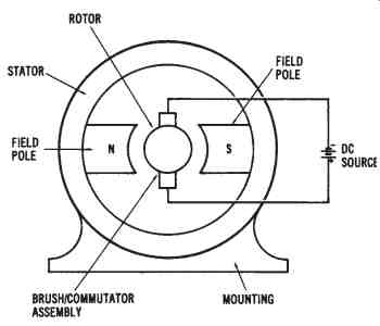
FIG. 1. Basic parts of a DC motor
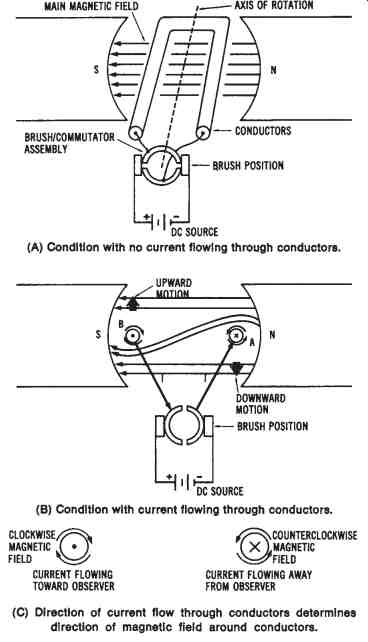
FIG. 2. Illustration of the basic motor principle: (A) Condition with
no current flowing through the conductors, (B) Condition with current
flowing through the conductors, (C) Direction of current flow through
the conductors deter mines the direction of the magnetic field around
the conductors
Sample Problem: Force Acting on a Conductor
When a current-carrying conductor is contained within a magnetic field, the force produced is called Lorentz force. This force is basic to the operation of electric motors. The force is greatest when the conductor is perpendicular to the magnetic field, and minimum (0) when it is parallel.
The maximum Lorentz force is expressed as:
F = B × l × l
where:
F = force acting on a conductor in newtons,
B = flux density in teslas,
l = length of the conductor in meters, and
I = current through the coil in amperes.
Given: a conductor 1.8 meters long has a current flow of 50 A through it. It is contained within a magnetic field of 0.25 tesla density.
Find: the maximum Lorentz force acting on the conductor.
Solution:
F = B × 1 × l
= 0.25 × 1.8 × 50
F = 22.5 newtons
The rotating effect produced by the interaction of two magnetic fields is called torque or motor action. The torque produced by a motor depends on the strength of the main magnetic field and the amount of current flowing through the conductors. As the magnetic field strength or the current through the conductors increases, the amount of torque or rotary motion will increase also.
DC MOTORS
Motors that operate from DC power sources are often used in industry when speed control is desirable. DC motors are almost identical in construction to DC generators. They are also classified in a similar manner as series, shunt, or compound machines, depending on the method of connecting the armature and field windings. The permanent-magnet DC motor is another type of motor that is used for certain applications.
DC Motor Characteristics
The general operational characteristics common to all DC motors are shown in FIG. 3. Most electric motors exhibit characteristics similar to those shown in the block diagram. In order to discuss DC motor characteristics, you should be familiar with the terms load, speed, counter-electromotive force (cemf), armature current, and torque. The amount of mechanical load applied to the shaft of a motor determines its operational characteristics. As the mechanical load is increased, the speed of a motor tends to decrease. As speed decreases, the voltage induced into the conductors of the motor through generator action (cemf) decreases. The generated volt age or counter-electromotive force depends upon the number of rotating conductors and the speed of rotation. Therefore, as speed of rotation de creases, so does the cemf.
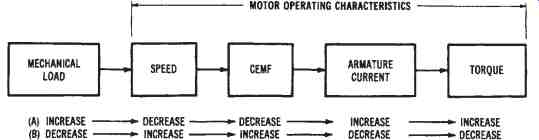
FIG. 3. Operational characteristics of DC motors.
The counter-electromotive force generated by a DC motor is in opposition to the supply voltage. Therefore, the actual working voltage of a DC motor may be expressed as:
VT = VC + IA RA where:
VT = the terminal voltage of the motor in volts,
VC = the cemf generated by the motor in volts, and
IA RA = the voltage drop across the armature of the motor in volts.
Since the cemf is in opposition to the supply voltage, the actual working voltage of a motor will increase as the cemf decreases. As the result of an increase in working voltage, more current will flow through the armature conductors that are connected to the DC power supply. Since torque is directly proportional to armature current, the torque will increase as the armature current increases.
To briefly discuss the opposite situation, if the mechanical load connected to the shaft of a motor decreases, the speed of the motor will tend to increase. An increase in speed causes an increase in generated voltage.
Since cemf is in opposition to the supply voltage, as cemf increases, the armature current decreases. A decrease in armature current causes a decrease in torque. We can see that torque varies with changes in load, but we need to consider each of the steps involved, in order to understand DC motor operation. As the load on a motor is increased, its torque also increases as the motor tries to meet the increased load requirement. However, the current drawn by a motor also increases when load is increased.
The presence of a cemf to oppose armature current is very important in motor operation. The lack of any cemf when a motor is being started explains why motors draw a very large initial starting current, compared to the running current they draw once full speed is reached. Maximum armature current flows when there is no cemf. As cemf increases, armature current decreases. Thus, resistances in series with the armature circuit are often used to compensate for the lack of cemf, and to reduce the starting current of a motor. After a motor has reached full speed, these resistances may be bypassed by automatic or manual switching systems, in order to allow the motor to produce maximum torque. Keep in mind that the armature current, which directly affects torque, can be expressed as:
VT - VC
IA = ---- RA
where:
IA = the armature current in amperes,
VT = the terminal voltage of the motor in volts,
VC = the cemf generated by the motor in volts, and
RA = the armature resistance in ohms.
In determining the functional characteristics of a motor, the torque developed can be expressed as:
T = K F IA
where:
T = the torque in foot-pounds,
K = a constant based on physical characteristics (conductor size, frame size, etc.),
F = the quantity of magnetic flux between poles, and
IA = the armature current in amperes.
Torque can be measured by several types of motor analysis equipment. The horsepower rating of a motor is based on the amount of torque produced at the rated full-load values. Horsepower, which is the usual method of rating motors, can be expressed mathematically as:
HP = the horsepower rating,
2p = a constant,
N = the speed of the motor in revolutions per minute (rpm), and
T = the torque developed by the motor in foot-pounds.
Sample Problem: Power of a Motor
The mechanical power output of a motor is dependent upon the speed of rotation and the torque produced. Power output is expressed as:
P = mechanical power in Watts,
n = speed of rotation in revolutions per minute (r/min),
T = torque in newtons per meter (N/m), and
9.55 = a constant equal to 30/pi.
Given: a motor rotating at 3,600 r/min produces a torque of 5N/m.
Find: the power output developed by the motor.
Another DC motor characteristic that we should discuss is armature reaction. Armature reaction was discussed in relation to DC generators in Section 7. This effect distorts the main magnetic field in DC motors, as well as in DC generators. Similarly, the brushes of a DC motor can be shifted to counteract the effect of armature reaction. However, interpoles are ordinarily used to control armature reaction in DC motors.
The most desirable characteristic of DC motors is their speed-control capability. Varying the applied DC voltage with a rheostat allows speed to be varied from zero to the maximum rpm of the motor. Some types of DC motors have more desirable speed characteristics than others. For this reason, we can determine the comparative speed regulation for different types of motors. Speed regulation is expressed as:
%SR = the percentage of speed regulation,
SNL = the no-load speed in rpm, and
SFL = the rated, full-load speed in rpm.
Sample Problem:
Given: the no-load speed of a universal motor is 6,250 r/min, and its full-load speed is 5,000 r/min.
Find: the motor's speed regulation.
Solution:
Good speed regulation (low % SR) results when a motor has nearly constant speeds under varying load situations.
Types of DC Motors
The types of commercially available DC motors basically fall into four categories: (1) permanent-magnet DC motors, (2) series-wound DC motors, (3) shunt-wound DC motors, and (4) compound-wound DC motors. Each of these motors has different characteristics that are due to its basic circuit arrangement and physical properties.
Permanent-Magnet DC Motors--The permanent-magnet DC motor, shown in FIG. 4, is constructed in the same manner as its DC generator counterpart, which was discussed in Section 7. The permanent-magnet motor is used for low-torque applications. When this type of motor is used, the DC power supply is connected directly to the armature conductors through the brush/commutator assembly. The magnetic field is produced by permanent magnets mounted on the stator.
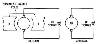
FIG. 4. Permanent-magnet DC motor
This type of motor ordinarily uses either alnico or ceramic permanent magnets, rather than field coils. The alnico magnets are used with high-horsepower applications. Ceramic magnets are ordinarily used for low-horsepower, slow-speed motors. Ceramic magnets are highly resistant to demagnetization, yet they are relatively low in magnetic-flux level.
The magnets are usually mounted in the motor frame, and then magnetized prior to the insertion of the armature.
The permanent-magnet motor has several advantages over conventional types of DC motors. One advantage is a reduced operational cost.
The speed characteristics of the permanent-magnet motor are similar to those of the shunt-wound DC motor. The direction of rotation of a permanent-magnet motor can be reversed by reversing the two power lines.
Series-wound DC Motors--The manner in which the armature and field circuits of a DC motor are connected determines its basic characteristics. Each type of DC motor is similar in construction to the type of DC generator that corresponds to it. The only difference, in most cases, is that the generator acts as a voltage source, while the motor functions as a mechanical power-conversion device.
The series-wound motor, shown in FIG. 5, has the armature and field circuits connected in a series arrangement. There is only one path for current to flow from the DC voltage source. Therefore, the field is wound of relatively few turns of large-diameter wire, giving the field a low resistance. Changes in load applied to the motor shaft cause changes in the cur rent through the field. If the mechanical load increases, the current also in creases. The increased current creates a stronger magnetic field. The speed of a series motor varies from very fast at no load, to very slow at heavy loads. Since large currents may flow through the low resistance field, the series motor produces a high torque output. Series motors are used when heavy loads must be moved, and speed regulation is not important. A typical application is automobile starter motors.
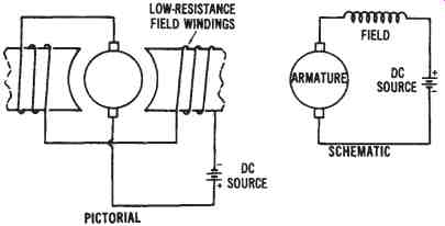
FIG. 5. Series-wound DC motor
Shunt-wound DC Motors--Shunt-wound DC motors are more commonly used than any other type of DC motor. As shown in FIG. 6, the shunt-wound DC motor has field coils connected in parallel with its armature. This type of DC motor has field coils that are wound of many turns of small-diameter wire and have a relatively high resistance. Since the field is a high-resistant parallel path of the circuit of the shunt motor, a small amount of current flows through the field. A strong electromagnetic field is produced because of the many turns of wire that form the field windings.
A large majority (about 95 percent) of the current drawn by the shunt motor flows in the armature circuit. Since the field current has little effect on the strength of the field, motor speed is not affected appreciably by variations in load current. The relationship of the currents that flow through a DC shunt motor is as follows:
IT = IA + IF where:
IT = the total current drawn from the power source,
IA = the armature current, and IF = the field current.
The field current may be varied by placing a variable resistance in series with the field windings. Since the current in the field circuit is low, a low-wattage rheostat may be used to vary the speed of the motor in accordance with the variation in field resistance. As field resistance increases, field current will decrease. A decrease in field current reduces the strength of the electromagnetic field. When the field flux is decreased, the armature will rotate faster, because of reduced magnetic-field interaction. Thus, the speed of a DC shunt motor may be easily varied by using a field rheostat.
The shunt-wound DC motor has very good speed regulation. The speed does decrease slightly when the load increases, as the result of the increase in voltage drop across the armature. Because of its good speed regulation, and its ease of speed control, the DC shunt motor is commonly used for industrial applications. Many types of variable-speed machine tools are driven by DC shunt motors.
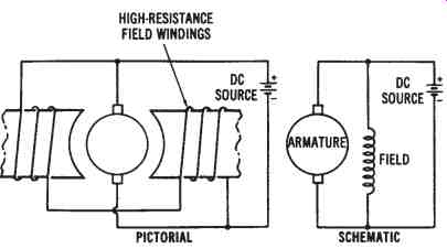
FIG. 6. Shunt-wound DC motor
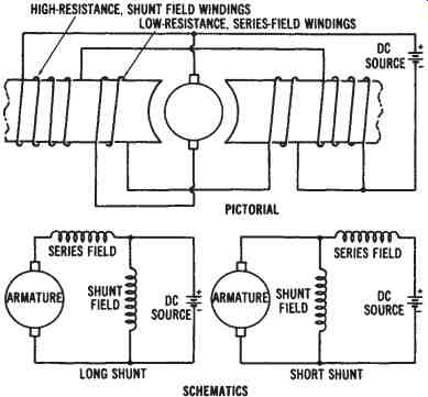
FIG. 7. Compound-wound DC motor
Compound-wound DC Motors---The compound-wound DC motor, shown in FIG. 7, has two sets of field windings, one in series with the armature and one in parallel. This motor combines the desirable characteristics of the series- and shunt-wound motors. It has high torque similar to that of a series-wound motor, along with good speed regulation similar to that of a shunt motor. Therefore, when good torque and good speed regulation are needed, the compound-wound DC motor can be used. A major disadvantage of a compound-wound motor is its expense.
Comparison of DC Motor Characteristics--The characteristics of DC motors should be considered when motors for particular applications are selected. FIG. 8 shows comparative graphs that illustrate the relative torque and speed characteristics of DC motors.
A DC motor is designed so that its shaft will rotate in either direction. It is a very simple process to reverse the direction of rotation of any DC motor. By reversing the relationship between the connections of the armature winding and field windings, reversal of rotation is achieved.
Usually, this is done by changing the terminal connections at the point where the power source is connected to the motor. Four terminals are ordinarily used for interconnection purposes. They may be labeled A1 and A2 for the armature connections, and F1 and F2 for the field connections. If either the armature connections or the field connections are reversed, the rotation of the motor will reverse. However, if both are reversed, the motor shaft will rotate in its original direction, since the relationship between the armature and field windings will be the same.
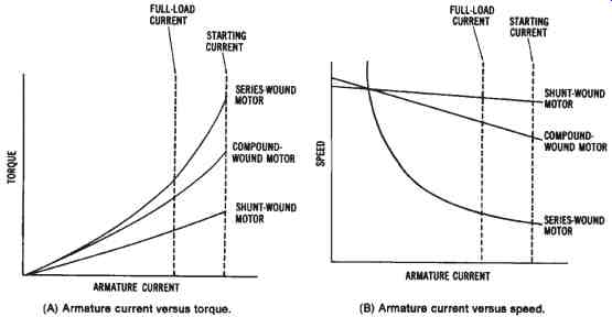
FIG. 8. Torque and speed characteristics of DC motors: (A) Armature
current versus torque, (B) Armature current versus speed
SPECIALIZED DC MOTORS
There are several specialized types of motors that operate on direct current. Among these are dynamotors, brushless DC motors, and DC step ping motors.
Dynamotors
One specialized type of DC motor is called a dynamotor. This motor, depicted in FIG. 9, converts DC voltage of one value to DC voltage of another value. It is actually a motor-generator housed in one unit. The armature has two separate windings. One winding is connected to the commutator of the motor section, and the other winding is connected to the commutator of a generator unit. A magnetic field, developed by either permanent magnets or electromagnetic windings, surrounds the armature assembly. Since the magnetic field remains relatively constant, the generator voltage output depends upon the ratio of the number of motor windings to the number of generator windings. For instance, if there are twice as many generator windings as motor windings, the generated DC-volt age output will be twice the value of the DC voltage that is input to the motor section of the dynamotor.
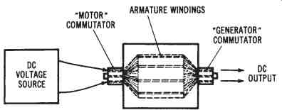
FIG. 9. Dynamotor construction
Brushless DC Motors
The use of transistors has resulted in the development of brush less DC motors, which have neither brushes nor commutator assemblies.
Instead, they make use of solid state switching circuits. The major problem with most DC motors is the low reliability of the commutator/brush assembly. The brushes have a limited life and cause the commutator to wear. This wearing produces brush dust, which can cause other maintenance problems.
Although some brushless DC motors use other methods, the transistor-switched motor is the most common (see FIG. 10). The motor it self is actually a single-phase, AC, permanent-capacitor, induction motor, with a center-tapped main winding. Transistors, operated by an oscillator circuit, conduct alternately through the paths of the main winding. The oscillator circuit requires a feedback winding wound into the stator slots, in order to generate a control voltage to determine the frequency. A capacitor (C2) is placed across the main winding to reduce voltage peaks and to keep the frequency of the circuit at a constant value.
The main disadvantage of this motor is its inability to develop a very high-starting torque. As a result, it is suitable only for driving very low torque loads. When used in a low-voltage system, this motor is not very efficient. Also, since only half of the main winding is in use at any instant, copper losses are relatively high. However, the advantages outweigh this disadvantage for certain applications. Since there are no brushes and commutator, motor life is limited mainly by the bearing. With proper lubrication, a brushless DC motor can be used for an indefinite period. Also, the motor frequency, and thus the speed, can be adjusted by varying the oscillator circuit.
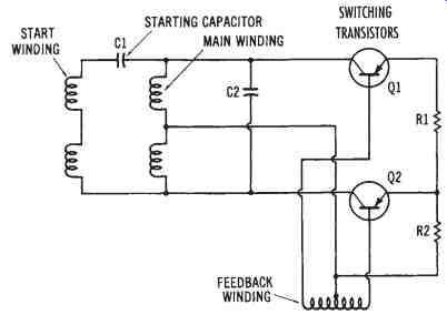
FIG. 10. A brushless DC motor circuit
DC Stepping Motors
DC stepping motors are unique DC motors that are used to control automatic industrial processing equipment. DC motors of this type are found in numerically controlled machines and robotic systems used by industry. They are very efficient and develop a high torque. The stepping motor is used primarily to change electrical pulses into a rotary motion that can be used to produce mechanical movements.
The shaft of a DC stepping motor rotates a specific number of mechanical degrees with each incoming pulse of electrical energy. The amount of rotary movement or angular displacement produced by each pulse can be repeated precisely with each succeeding pulse from the drive source.
The resulting output of this device is used to accurately locate or position automatic process machinery.
The velocity, distance, and direction of movement of a specific ma chine can be controlled by DC stepping motors. The movement error of this device is generally less than 5 percent per step. This error factor is not cumulative, regardless of the distance moved, or the number of steps taken. Motors of this type are energized by a DC drive amplifier that is con trolled by digital logic circuits. The drive-amplifier circuitry is a key factor in the overall performance of this motor. The stator construction and coil layout are shown in FIG. 11. The rotor of a stepping motor is of a permanent-magnet type of construction.
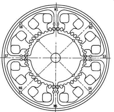
FIG. 11. Stator and coil layout of a DC stepping motor.
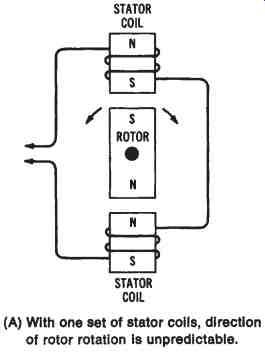
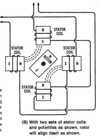
FIG. 12. Illustration of the magnetic principle involved in the operation
of a DC stepping motor: (A) With one set of stator coils, direction
of rotor rotation is unpredictable, (B) With two sets of stator coils and
polarities as shown, rotor will align itself as shown.
A very important principle that applies to the operation of a DC step ping motor is that like magnetic poles repel, and unlike magnetic poles at tract. If a permanent-magnet rotor is placed between two series-connected stator coils, it produces the situation shown in FIG. 12. With power applied to the stator, the rotor can be repelled in either direction. The direction of rotation in this case is unpredictable. Adding two more stator coils to a simple motor, as indicated in FIG. 12B, will make the direction of rotation predictable. With the stator polarities indicated, the rotor will align itself midway between the two pairs of stator coils. The direction of rotation can now be predicted, and is determined by the polarities of the stator-coil sets. Adding more stator-coil pairs to a motor of this type improves its rotation and makes the stepping action very accurate.
FIG. 13 shows an electrical diagram of a DC stepping motor.
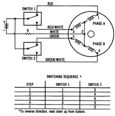
FIG. 13. Circuit diagram and switching sequence of a DC stepping motor.
The stator coils of this motor are wound in a special type of construction called bifilar. Two separate wires are wound into the coil slots at the same time. The two wires are small in size, which permits twice as many turns as can be achieved with a larger-sized wire. Construction of this type simplifies the control circuitry and DC energy-source requirements.
Operation of the stepping motor illustrated in FIG. 13 is achieved in a four-step switching sequence. Any of the four combinations of switches 1 or 2 will produce an appropriate rotor position location. After the four switch combinations have been achieved, the switching cycle repeats it self. Each switching combination causes the motor to move one-fourth of a step.
A rotor, similar to the one shown in FIG. 13 normally has 50 teeth. Using a 50-tooth rotor in the circuit of FIG. 13 would permit four steps per tooth, or 200 steps per revolution. The amount of displacement, or step angle, of this motor is, therefore, determined by the number of teeth on the rotor, and by the switching sequence.
A stepping motor that takes 200 steps to produce one revolution will move 360 degrees every 200 steps, or 1.8 degrees per step. It is not unusual for stepping motors to use eight switching combinations to achieve one step. In this case, each switching combination could be used to produce 0.9 degree of displacement. Motors and switching circuits of this type permit a very precise type of controlled movement.
SINGLE-PHASE AC MOTORS
Another broad classification of mechanical power-conversion equipment includes single-phase AC motors. These motors are common for industrial as well as commercial and residential usage. They operate from a single-phase AC power source. There are three basic types of single-phase AC motors-universal motors, induction motors, and synchronous motors.
Universal Motors
Universal motors may be powered by either AC or DC power sources. The universal motor, shown in FIG. 14 is constructed in the same way as a series-wound DC motor. However, it is designed to operate with either AC or DC applied. The series-wound motor is the only type of DC motor that will operate with AC applied. The windings of shunt-wound motors have inductance values that are too high to allow the motor to function with AC applied. However, series-wound motors have windings that have low inductances (few turns of large diameter wire), and they therefore offer a low impedance to the flow of AC. The universal motor is one type of AC motor that has concentrated or salient field windings.
These field windings are similar to those of all DC motors.
The operating principle of the universal motor, with AC applied, involves the instantaneous change of both field and armature polarities.
Since the field windings have low inductance, the reversals of field polarity brought about by the changing nature of the applied AC also create reversals of current direction through the armature conductors at the proper time intervals. The universal motor operates in the same manner as a series-wound DC motor, except that the field polarity and the direction of armature current change at a rate of 120 times per second when connected to a 60-Hz AC source. The speed and torque characteristics of universal motors are similar to those of DC series-wound motors. Universal motors are used mainly for portable tools and small, motor-driven equipment, such as mixers and blenders.
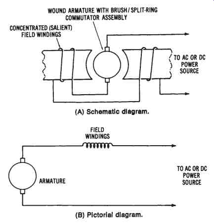
FIG. 14. The universal motor: (A) Schematic diagram, (B) Pictorial
diagram
Induction Motors
Another popular type of single-phase AC motor operates on the induction principle. This principle is illustrated in FIG. 15. The coil symbols along the stator represent the field coils of an induction motor.
These coils are energized by an AC source; therefore, their instantaneous polarity changes 120 times per second when 60-Hz AC is applied.
Induction motors have a solid rotor, which is referred to as a squirrel-cage rotor. This type of rotor, which is illustrated in FIG. 15B, has large-diameter copper conductors that are soldered at each end to a circular connecting plate. This plate actually short circuits the individual conductors of the rotor. When current flows in the stator windings, a current is induced in the rotor. This current is developed by means of "transformer action" between the stator and rotor. The stator, which has AC voltage applied, acts as a transformer primary. The rotor is similar to a transformer secondary, since current is induced into it.
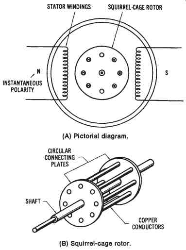
FIG. 15. Illustration of the induction principle: (A) Pictorial diagram,
(B) Squirrel-cage rotor.
