AMAZON multi-meters discounts AMAZON oscilloscope discounts
Alternating Current (AC) is used in greater quantities than direct current (DC); however, many important operations are dependent upon DC power. Industries use DC power for many specialized processes.
Electroplating and DC variable-speed motor drives are only two examples that show the need for DC power to sustain industrial operations. We use DC power to start our automobiles, and many types of portable equipment in the home use DC power. Most of the electrical power produced in the United States is three-phase AC, and this three-phase AC power may be easily converted to DC for industrial or commercial use. Direct current is also available in the form of primary and secondary chemical cells. These cells are used extensively. In addition, DC generators are also used to sup ply power for specialized applications.
TERMINOLOGY
This section (section 7) deals with DC power systems. After studying this Section, you should have an understanding of the following terms:
- Primary Cell
- Secondary Cell
- Electrolyte Electrode
- Battery
- Internal Resistance
- Carbon-Zinc Cell
- Mercury Cell
- Alkaline Cell
- Nuclear Cell
- Lead-Acid Cell
- Specific Gravity
- Ampere-Hour Rating
- Nickel-Iron ( Edison) Cell
- Nickel-Cadmium Cell
- Silver Cell
- DC Generator
- Split-Ring Commutator
- DC Permanent-Magnet Generator
- DC Separately Excited Generator
- DC Self-Excited Series-Wound Generator
- DC Self-Excited Shunt-Wound Generator
- DC Self-Excited Compound-Wound Generator
- Armature Reaction
- Interpoles
- Rectification
- Single-Phase, Half-Wave Rectifier
- Single-Phase, Full-Wave Rectifier
- Single-Phase, Bridge Rectifier
- Three-Phase, Half-Wave Rectifier
- Three-Phase, Full-Wave Rectifier
- Silicon-Controlled Rectifier (SCR)
- Rotary Converter
- Filter Circuit
- Capacitor Filter
- RC Filter
- Π (p) Filter
- Regulation
- Zener Diode Regulator
- Series Transistor Regulator
- Shunt Transistor Regulator
DC PRODUCTION USING CHEMICAL CELLS
The conversion of chemical energy into electrical power can be accomplished by the use of electrochemical cells. A cell is composed of two dissimilar metals, which are immersed in a conductive liquid or paste called an electrolyte. Chemical cells are classified as either primary cells or secondary cells. Primary cells are ordinarily not usable after a certain period of time. After this period of time its chemicals can no longer produce electrical energy. Secondary cells can be renewed after they are used, by reactivating the chemical process that is used to produce electrical energy. This reactivation is known as charging. Both primary cells and secondary cells have many applications. When two or more cells are connected in series, they form a battery.
CHARACTERISTICS OF PRIMARY CELLS
The operational principle of a primary cell involves the placing of two unlike conductive materials called electrodes into a conductive solution called an electrolyte. When the chemicals that compose the cell are brought together, their molecular structures are altered. During this alteration, their atoms may either gain additional electrons or lose some of their electrons. These atoms then have either a positive or a negative electrical charge, and are referred to as ions. The ionization process thus develops a chemical solution capable of conducting an electrical current. A carbon-zinc primary cell is shown in FIG. 1.
When an external load device, such as a lamp, is connected to a cell, a current will flow from one electrode to the other through the electrolyte material. Current leaves the cell through its negative electrode, flows through the load device, then reenters the cell through its positive electrode, as shown in FIG. 2. Thus, a complete circuit is established between the cell (source) and the lamp (load).
The voltage developed by a primary cell is dependent upon the electrode materials and the type of electrolyte used. The familiar carbon-zinc cell of FIG. 1 produces approximately 1.5 volts. The negative electrode of the cell is the zinc container, and the positive electrode is a carbon rod.
A sal ammoniac paste, which acts as the electrolyte, is placed between the electrodes. This type of cell is usually called a dry cell.
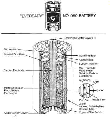
FIG. 1. Batteries-Common sources of direct current (DC): Cutaway of a
general purpose carbon-zinc cell (Eveready Corp.)
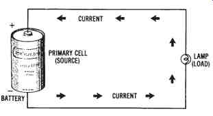
FIG. 2. Current path for
a primary cell
Internal Resistance of Cells
An important characteristic of a chemical cell is its internal resistance.
Since a cell conducts electrical current, its resistance depends on its cross sectional area, the length of its current path, the type of materials used, and the operational temperature. The amount of current that a cell will de liver to a load is expressed as:
V
I = ----- Ri
+ RL where:
I = the current in amperes,
V = the voltage or electromotive force (emf) of the cell in volts,
Ri
= the internal resistance of the cell in ohms, and
RL = the resistance of the load in ohms.
Sample Problem:
Given: a 1.5 volt battery has an internal resistance of 0.8 ohms.
Find: load current when 10.0 ohms of load resistance is connected to the battery.
Solution:
1.5 V
I = ------ 0.8 + 10.00O
= 0.139 A
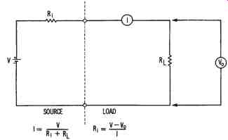 FIG. 3. Illustrating the internal resistance of a cell
This formula, and another circuit that illustrates it, are shown in FIG. 3. The formula shows that when a cell delivers current to a load, some of the voltage developed must be used to overcome the internal resistance of the cell. As load current increases, the voltage drop (I × R) with in the cell increases. This increased voltage drop causes the output voltage (Vo) of the cell to decrease. Thus,
Vo = V - IRi where:
Vo = the output voltage of the cell in volts,
V = the no-load cell voltage in volts,
I = the load current in amperes, and
Ri
= the internal resistance of the cell in ohms.
Sample Problem:
Given: the no-load voltage of a battery is 9.05 volts. Its rated load current is 200 mA, and its internal resistance is 0.1 ohms.
Find: the rated output voltage of the battery.
Solution:
Vo = V - IRi
= 9.05 V - (.2 A × 0.1 Ohm)
Vo = 9.03 Volts Modifying this formula to solve directly for Ri , we obtain
V - Vo
Ri
= --- I
Sample Problem:
Given: the rated output of a battery is 30.0 volts, and its no-load volt age is 30.15 volts. Its full-load current is 350 mA.
Find: the internal resistance of the battery.
Solution:
V - Vo
Ri= --- I
30.15 - 30.0 V= ------- 0.35 A
Ri= 0.43 ohms
The same method is used to determine the internal resistance of all voltage sources, including primary cells, secondary cells, and generators.
Applications of Primary Cells
There are many types of primary cells available today, with unlimited applications. The carbon-zinc (or Lechanche) cell, discussed previously, is the most often used type of dry cell. This cell has a low initial cost and is available in a variety of sizes. It is used primarily for portable equipment or instruments. For uses that require a higher voltage or current than one cell can deliver, manufacturers combine several cells in series, parallel, or series-parallel arrangements to form batteries suitable for specialized applications. Carbon-zinc batteries can be obtained in voltage ratings from 1.5 volts, at over I-ampere capability, up to about 3000 volts.
Mercury Cells-Another type of primary cell is the mercury or zinc mercuric oxide cell, shown in FIG. 4. This cell was developed as an improvement of the carbon-zinc cell. The mercury cell has a more constant voltage output, a longer active service time, and a smaller physical size.
However, the mercury cell is more expensive and produces a voltage of 1.35 volts, which is lower than that of the carbon-zinc cell.
Alkaline Cells-An alkaline or zinc-magnesium dioxide cell, shown in FIG. 5, is another type of primary cell. These cells have very low internal resistance and a voltage per cell of 1.5 volts. Because of their low internal resistance, alkaline cells will supply higher currents to the electrical loads connected to them. Alkaline cells are capable of a much longer service life than the equivalent carbon-zinc cells.
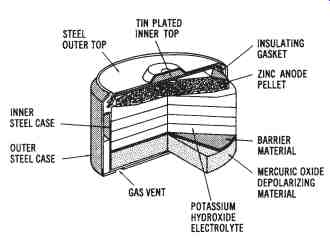
FIG. 4. Cutaway drawing of a mercury primary cell
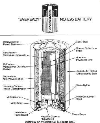
FIG. 5. Alkaline cells: Cutaway of a cylindrical alkaline cell
Nuclear Cells--A recent source of DC power that has been developed is the nuclear cell. Such cells convert the energy given off by atomic nuclei into electrical energy. At present, a high-voltage type (thousands of volts with a picoampere current capacity) and a low-voltage type (approximately 1 volt with a microampere current capability) are available.
The illustration in FIG. 6 shows the design of one type of nuclear cell. The radioactive source is connected to one electrode of the cell. The source used here is tritium gas absorbed in zirconium metal, which emits beta particles. The carbon-collector electrode collects these beta particles as they are emitted from the tritium source, thus producing an electrical charge. The electrodes are separated by either a vacuum or some other type of dielectric, which electrically isolates the two electrodes. The nu-clear cell shown in FIG. 6 has air removed through the center tube to form the vacuum inside it that isolates the positive and negative electrodes. The DC output produced by this cell is extracted through terminals connected to the tritium source (negative) and to the carbon connector (positive). The output of this cell is dependent upon the nuclear energy generated by the tritium source; therefore, the voltage output decreases as the cell ages.
CHARACTERISTICS OF SECONDARY CELLS
Regardless of the type of primary cell used, its usable time is limited.
When its chemicals are expended, it becomes useless. This disadvantage is overcome by secondary cells. The chemicals of a secondary cell may be reactivated by a charging process. Secondary cells are also called storage cells.
The most common types of secondary cells are the lead-acid cell, nickel-iron ( Edison) cell, and nickel-cadmium cell
The Lead-acid Cell
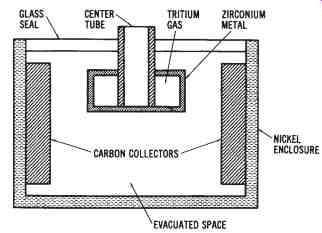
FIG. 6. Cutaway drawing of a nuclear cell
The widely used lead-acid cell is one type of secondary cell. The electrodes of the lead-acid cell are made of lead and lead peroxide. The positive plate is lead peroxide (PbO2), and the negative plate is lead (Pb). The electrolyte is dilute sulfuric acid (H2SO4). When the lead-acid cell supplies current to a load connected to it, the chemical process can be expressed as:
PbO2 + Pb + 2H2SO4 = 2PbSO4 + 2H2O.
The sulfuric acid ionizes to produce four positive hydrogen ions (H+) and two negative sulfate (SO4-) ions. A negative charge is developed on the lead plate when an SO4- ion combines with the lead plate to form lead sulfate (PbSO4). The positive hydrogen ions (H+) combine with electrons of the lead-peroxide plate and become neutral hydrogen atoms. They next combine with the oxygen (O) of this plate to become water (H2O). The lead-peroxide plate thus becomes positively charged. A fully charged lead acid cell has an electrical potential developed between electrodes of approximately 2.0 volts.
After a cell discharges by supplying current to a load for a certain period of time, it is no longer able to develop an output voltage. The cell may then be charged by causing direct current to flow through the cell in the opposite direction.
The chemical process is thus reversed as follows:
2Pb SO4 + 2H2O = PbO2 + Pb + 2H2SO4.
Thus, the original state of the chemicals is reestablished by the charging action.
Specific Gravity of Secondary Cells
The amount of charge may be measured by a specific-gravity test using a hydrometer to sample the electrolyte. The specific gravity of a liquid provides an index of how much heavier than water the liquid is. Pure sulfuric acid has a specific gravity of 1.840, while the dilute sulfuric acid of a fully charged lead-acid cell varies from 1.275 to 1.300. During discharge of a cell, water is formed, reducing the specific gravity of the electrolyte. A specific gravity of between 1.120 and 1.150 indicates a fully discharged cell.
Recharging is accomplished using battery chargers.
Ampere-hour Rating of Secondary Cells
The capacity of a battery composed of lead-acid cells is given by an ampere-hour rating. A 60-ampere hour battery could theoretically deliver 60 amperes for 1 hour, 30 amperes for 2 hours, or 15 amperes for 4 hours.
However, this is an approximate rating dependent upon the rate of discharge and the operating temperature of the battery. The normal operating temperature is considered to be 80 deg.Fahrenheit.
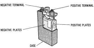
FIG. 7. Cutaway drawing of a nickel-iron ( Edison) secondary cell
Nickel-iron Cells
The nickel-iron (or " Edison") cell, shown in FIG. 7 is a secondary cell constructed with an unbreakable case of welded nickel-plated sheet steel. The positive plate is made of nickel tubes about V. inch in diameter and 4-1/4 inches long. Nickel oxide (NiO2) is contained in the tubes, which are mounted into steel grids and forced into position under high pressure. The positive plates are assembled into groups. The negative plates of the Edison cell are made of ?at nickel-plated steel pockets, which are composed of iron oxide. They are built into steel grids in groups, in the same way as the positive plates. The electrolyte is a solution of potassium hydroxide (KOH) with lithium hydroxide added.
Chemical action of the nickel-oxide cell is very complex as compared to that of the lead-acid cell; however, they are similar in many respects.
The potassium hydroxide electrolyte (KOH) breaks up into negative and positive ions. The negative ions move toward the iron plate, oxidize the iron, and give up excess electrons to the plate. This plate becomes negatively charged. The positive ions move to the nickel-oxide plate and take electrons from the plate. The deficiency of electrons causes the nickel-oxide plate to become positively charged. The voltage produced by the chemical action of a nickel-iron cell is about 1.4 volts.
The internal resistance of the nickel-iron ( Edison) cell is higher than that of the lead-acid cell. This resistance increases quickly as the cell discharges. Unlike the lead-acid cell, the nickel-iron cell cannot be tested using a hydrometer to show its discharge level. A voltmeter is used to indicate the state of charge of the nickel-iron cell. This cell is also charged by applying a DC voltage to the positive and negative terminals and causing current within the cells to flow in reverse. The chemicals are thus reactivated so that the cells may be used again.
Other Types of Secondary Cells
Another type of secondary cell that has gained recent popularity is the nickel-cadmium cell, sometimes called a "Ni-cad" battery. These cells are avail able in large or small sizes with capacities up to 2000 ampere-hours. FIG. 8 shows the small rechargeable type of nickel-cadmium cell, which is used extensively in portable equipment. The positive plate of this cell is nickel hydroxide, the negative plate is cadmium hydroxide, and the electrolyte is potassium hydroxide. These cells are extremely reliable, operate over a wide range of temperatures, and have a long life expectancy. A fully charged nickel-cadmium cell has a voltage of approximately 1.35 volts per cell.
There are a few other types of secondary cells in use today. Most of these types are for specialized applications. Other cells include the silver oxide-zinc cell and the silver-cadmium cell. These cells have the highest out put per physical size and the longest life, but they are more expensive than other cells.
Applications of Secondary Cells
Secondary cells, in the form of storage batteries, are used in industry and commercial buildings to provide emergency power in the event of a power failure. Such standby systems are necessary to sustain lighting and some critical operations when power is not available. Industrial trucks and loaders use storage batteries for their everyday operation. Many types of instruments and portable equipment rely upon batteries for power. Several of these instruments get their power from rechargeable secondary cells rather than primary cells. Railway cars use batteries for lighting when they are not in motion. Of course, automotive systems of all kinds use secondary batteries to supply DC power for starting and lighting.
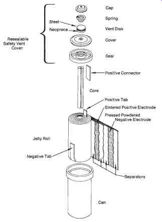
FIG. 8. Sealed nickel-cadmium rechargeable cylindrical type cell-exploded
view (Eveready Corp.)
DC GENERATING SYSTEMS
Mechanical generators are used in many situations to produce direct current. These generators convert mechanical energy into DC electrical energy.
Construction of DC Generators
The parts of a simple DC generator are shown in FIG. 9. The principle of operation of a DC generator is similar to that of the AC generator, which was discussed previously. A rotating armature coil passes through a magnetic field that develops between the north and south polarities of permanent magnets or electromagnets. As the coil rotates, electromagnetic induction causes a current to be induced into the coil. The current produced is an alternating current. However, it is possible to convert the alternating current that is induced into the armature into a form of direct current.
This conversion of AC into DC is accomplished through the use of a split ring commutator. The conductors of the armature of a DC generator are connected to split-ring commutator segments. The split-ring commutator shown in FIG. 12 has two segments, which are insulated from one an other and from the shaft of the machine on which it rotates. An end of each armature conductor is connected to each commutator segment. The purpose of the split-ring commutator is to reverse the armature-coil connection to the external load circuit at the same time that the current induced in the armature coil reverses. This causes DC of the correct polarity to be applied to the load at all times.
Voltage Output of DC Generators
The voltage developed by the single-coil generator shown in FIG. 9 would appear as illustrated in FIG. 10. This pulsating DC is not suitable for most applications. However, using many turns of wire around the armature and several split-ring commutator segments causes the volt age developed to be a smooth, direct current like that produced by a battery. This type of output is shown in FIG. 10b. The voltage developed by a DC generator depends upon the strength of the magnetic field, the number of coils in the armature, and the speed of rotation of the armature.
By increasing any of these factors, the voltage output can be increased.
Sample Problem: Voltage Output of a DC Generator
Voltage output of a DC generator can be expressed as:
Z × n × F
Vo = ---- 60 where:
Vo = voltage developed across the generator brushes in volts,
Z = total number of armature conductors,
n = speed of rotation in r/min, and
F = magnetic flux per pole in webers.
Given: a four-pole DC generator rotates at 1200 r/min. The armature has 36 slots, and each coil has four turns of wire. The magnetic flux per pole is 0.05 webers.
Find: the voltage output of the generator.
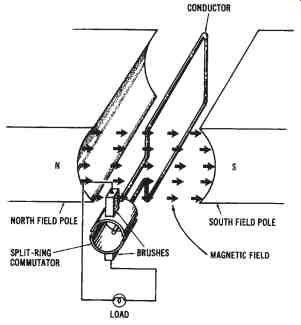
FIG. 9. Simplified drawing of the basic parts of a DC generator
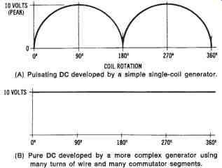
FIG. 10. Output waveforms of a DC generator: (A) Pulsating DC developed
by a simple single-coil generator, (6) Pure DC developed by a more complex
generator using many turns of wire and many commutator segments
Solution: since each turn has 2 conductors, and 36 slots are used in the armature core, Z = 36 coils × 2 coils per turn × 4 turns of wire per coil
= 288 conductors.
288 × 1200 × 0.05
Vo = -------- 60
Vo = 288 volts
Types of DC Generators
DC generators are classified according to the way in which a magnetic field is developed in the stator of the machine. One method is to use a permanent-magnet field. It is also possible to use electromagnets to develop a magnetic field by applying a separate source of DC to the electromagnetic coils. However, the most common method of developing a magnetic field is for part of the generator output to be used to supply DC power to the field of the machine. Thus, there are three basic classifications of DC generators: (1) permanent-magnet field, (2) separately excited field, and (3) self excited field. The self-excited types are further subdivided according to the method used to connect the armature windings to the field circuit. This can be accomplished by the following connection methods: (1) series, (2) parallel (shunt), or (3) compound.
Permanent-magnet DC Generator--A simplified diagram of a permanent-magnet DC generator is shown in FIG. 11. The conductors shown in this diagram are connected to the split-ring commutator and brush assembly of the machine. The magnetic field is established by using permanent magnets made of Alnico (an alloy of aluminum, nickel, cobalt, and iron), or some other naturally magnetic material. It is possible to group several permanent magnets together to create a stronger magnetic field.
The armature of the permanent-magnet DC generator consists of many turns of insulated conductors. Therefore, when the armature rotates within the permanent-magnetic field, an induced voltage develops that can be applied to a load circuit. Applications for this type of DC generator are usually confined to those that require low amounts of power. A magneto is an example of a permanent-magnet DC generator.
Separately Excited DC Generator--Where large amounts of DC electrical energy are needed, generators with electromagnetic fields are used.
Stronger fields can be produced by electromagnets. It is possible to control the strength of the electromagnetic field by varying the current through the field coils. The output voltage of generators that use electromagnetic fields can be controlled with ease.
The direct current used to establish the electromagnetic field is referred to as the excitation current. When DC excitation current is obtained from a source separate from the generator, the generator is called a separately excited DC generator. This type of generator is shown in FIG. 12.
Storage batteries are often used to supply the DC excitation current to this type of generator. The field current is independent of the armature cur rent. Therefore, the separately excited generator maintains a very stable output voltage. Changes in load of the external circuit affect the armature current, but do not vary the strength of the field. The voltage output of a separately excited DC generator can be varied by adjusting the current through the field. A high-wattage rheostat (variable resistance) connected in series with the field coils will accomplish field control of a separately excited DC generator.
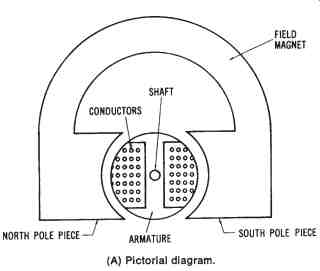
FIG. 11. Simplified drawing of a permanent-magnet DC generator: (A) Pictorial
diagram, (B) Schematic diagram
Separately excited DC generators are used only in certain applications where precise voltage control is essential. Automatic control processes in industry often require such precision. However, the cost of a separately excited DC generator is often prohibitive, and, therefore, other means of obtaining DC electrical power are usually used.
Self-excited Series-wound DC Generators-Since DC generators pro duce direct current, it is possible to extract part of the output of a genera tor to obtain excitation current for the field coils. Generators that use part of their own output to supply the excitation current for the electromagnetic field are called self-excited DC generators. The method used to connect the armature windings to the field windings determines the characteristics of the generator. It is possible to connect armature and field windings in series, parallel (shunt), or series-parallel (compound).
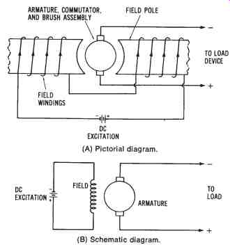
FIG. 12. Simplified illustration of a separately excited DC generator:
(A) Pictorial diagram, (B) Schematic diagram
The self-excited series-wound DC generator has its armature windings connected in series with the field coils and the load circuit, as shown in FIG. 13. In this generator, the total current flowing through the load also flows through the field coils. The field coils are, therefore, wound using only a few turns of low-resistance large-diameter wire. A sufficient electromagnetic field can then be produced by the large current flowing through the coils.
If the load circuit is disconnected, no current flows through the generator. However, the field coils retain a small amount of magnetism known as residual magnetism. Because of residual magnetism, a current will begin to flow through the generator and the load circuit when a load circuit is connected. The current will continue to increase, thus causing an increase in the magnetic strength of the field. The output voltage rises proportion ally with increases in current flow through the load and generator circuits.
The output curve of a series-wound DC generator is shown in FIG. 14.
The peak of the curve is reached when magnetic saturation of the field occurs. Magnetic saturation prohibits any increase in output voltage. After saturation is reached, any increase in load current causes a rapid decline in the output voltage due to circuit losses.
The output voltage of a self-excited series-wound DC generator varies appreciably with changes in load current. However, beyond the peak of its output curve, the load current remains fairly stable, even with large variations in voltage. There are specific applications, such as arc welding, that require stable load current as the voltage changes. However, the self excited series-wound generator has very few applications.
Self-excited Shunt-wound DC Generator--connecting the field coils, the armature circuit, and the load circuit in parallel produces a shunt-wound DC generator configuration. FIG. 15 shows this type of generator. The output current developed by the generator (IA) has one path through the load circuit (IL) and another through the field coils (IF). The generator is usually designed so that the field current is not more than 5 percent of the total armature current (IA).
In order to establish a strong electromagnetic field and to limit the amount of field current, the field coils are wound with many turns of small diameter wire. These high-resistance coils develop a strong field that is due to the number of turns, and, therefore, they rely very little on the amount of field current to develop a strong magnetic field.
With no load circuit connected to the shunt-wound DC generator, an induced voltage is produced as the armature rotates through the electro magnetic field. Again, the presence of residual magnetism in the field coils is critical to the operation of the machine. A current flows in the armature and field circuit as long as there is residual magnetism. As the generated current increases, the output voltage also increases, up to a peak level.
When a load circuit is connected to the shunt generator, the armature current (IA) increases, because of the additional parallel path. This, then, will increase the I × R drop in the armature, resulting in a smaller output voltage. Further increases in load current cause corresponding decreases in output voltage, as shown in the output curve of FIG. 16. With small load currents, the output voltage remains nearly constant as load current varies. A large load causes the armature current to decrease. This decrease is desirable because it provides the generator with a built-in protective feature, in case of a short circuit.
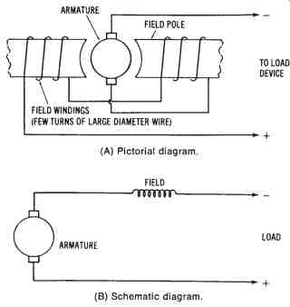
FIG. 13. Simplified illustration of a self-excited, series-wound DC generator:
(A) Pictorial diagram, (8) Schematic diagram
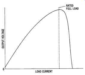
FIG. 14. The output curve of a series-wound DC generator

FIG. 15. Simplified illustration of a self-excited, shunt-wound DC generator:
(A) Pictorial diagram, (B) Schematic diagram
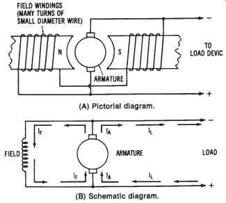
FIG. 16. Output curve of a shunt-wound DC generator
The self-excited shunt-wound DC generator is used when a constant output voltage is needed. It may be used to supply excitation current to a large AC generator or to charge storage batteries. However, in applications where initial expense is not critical, the compound-wound generator described next may be more desirable.
Self-excited Compound-wound DC Generator--The compound-wound DC generator has two sets of field windings. One set is made of low-resistance windings and is connected in series with the armature circuit. The other set is made of high-resistance wire and is connected in parallel with the armature circuit. A compound-wound DC generator is illustrated in FIG. 17.
As discussed previously, the output voltage of a series-wound DC generator increases with an increase in load current, while the output volt age of a shunt-wound DC generator decreases with an increase in load current. It is possible to produce a DC compound-wound generator, utilizing both series and shunt windings, that has an almost constant voltage output under changing loads. A constant voltage output can be obtained with varying loads, if the series-field windings have the proper characteristics to set up a sufficient magnetic field to counterbalance the voltage reduction caused by the I × R drop in the armature circuit.
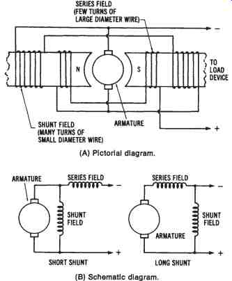
FIG. 17. Simplified illustration of a compound-wound DC generator,: (A) Pictorial diagram, (B) Schematic diagram
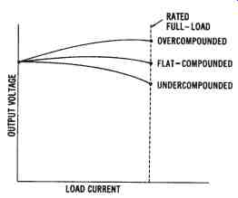
FIG. 18. Output curves for a compound-wound DC generator
A constant output voltage is produced by a flat-compounded DC generator. The no-load voltage is equal to the rated full-load voltage in this type of machine, as shown by the output curves in FIG. 18. If the series windings produce a stronger field, the generator will possess a series characteristic. The voltage output will increase with an increase in load.
A compound-wound generator whose full-load voltage is greater than its no-load voltage is called an overcompounded DC generator. Likewise, if the shunt windings produce a stronger field, the output will be more characteristic of a shunt generator. Such a generator, whose full-load voltage is less than its no-load voltage, is called an undercompounded DC generator.
Compound-wound DC generators can be constructed so that the series and shunt fields either aid or oppose one another. If the magnetic polarities of adjacent fields are the same, the magnetic fields aid each other and are said to be cumulatively wound. Opposing polarities of adjacent coils produce a differentially wound machine. For almost all applications of com pound-wound machines, the cumulative-wound method is used. A generator wound in this way maintains a fairly constant voltage output with variations in load current. The compound-wound DC generator is used more extensively than other DC generators, because of its constant volt age output and its design flexibility, which allows it to obtain various out put characteristics.
