AMAZON multi-meters discounts AMAZON oscilloscope discounts
One of the most efficient methods of electrical power control that is circuit switching. When a switch is turned on, power is consumed by the load device. When a switch in any circuit is turned off, no power is consumed. This switching method of power control is shown in FIG. 1 using a lamp as the load device. Since the switch is low resistant, it consumes little power. When the switch is open, it consumes no power. By switching the circuit on and off rapidly, the average current flow can be reduced. The brightness of the lamp will also be reduced. In effect, lamp brightness is controlled by the switching speed. Power in this method of control is not consumed by the control device. This type of power control is both efficient and effective.
The switching method of electrical power control cannot be achieved effectively with a manual switch. The mechanical action of the switch will not permit it to be turned on and off quickly. A switch would soon wear out if used in this manner. Electronic switching can be used to achieve the same result. Switching action of this type can be accomplished in a circuit without a noticeable flicker of a lamp. Electronic control devices such as silicon controlled rectifiers and triacs are used with the switching method for controlling power. The operation of these devices is described in this Section.
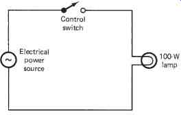
FIG. 1. Switch-controlled lamp circuit.
TERMINOLOGY
This Section describes control devices that are commonly used in electrical power control systems. After studying this Section, you should have an understanding of the following terms:
- Silicon Controlled Rectifier (SCR)
- Circuit Switching
- I-V Characteristics
- DC Power Control
- AC Power Control
- Triac
- Static Switching
- Start-Stop Control
- Diac
SILICON-CONTROLLED RECTIFIERS
A silicon-controlled rectifier or SCR is probably the most popular electronic power control device today. The SCR is used primarily as a switching device. Power control is achieved by switching the SCR on and off during one alter-nation of the ac source voltage. For 60 Hz ac the SCR would be switched on and off 60 times per second. Control of electrical power is achieved by altering or delaying the turn-on time of an alternation.
An SCR, as the name implies, is a solid-state rectifier device. It con ducts current in only one direction. It is similar in size to a comparable silicon power diode. SCRs are usually small, rather inexpensive, waste little power, and require practically no maintenance. The SCR is available today in a full range of types and sizes to meet nearly any power control application. Presently, they are available in current ratings from less than 1A to over 1400A. Voltage values range from 15 to 2600V.
SCR Construction
An SCR is a solid-state device made of four alternate layers of P- and N-type silicon. Three P-N junctions are formed by the structure. Each SCR has three leads or terminals. The anode and cathode terminals are similar to those of a regular silicon diode. The third lead is called the gate. This lead determines when the device switches from its off to on state. An SCR will usually not go into conduction by simply for-ward biasing the anode and cathode. The gate must be forward biased at the same time. When these conditions occur, the SCR becomes conductive. The internal resistance of a conductive SCR is less than 1 Ohm. Its reverse or off-state resistance is generally in excess of 1 M-Ohm. This allows the device to be similar to a mechanical switch.
A schematic symbol and the crystal structure of an SCR are shown in FIG. 2. Note that the device has a PNPN structure from anode to cathode. Three distinct P-N junctions are formed. When the anode is made positive and the cathode negative, junctions 1 and 3 are forward biased.
J2 is reverse biased. Reversing the polarity of the source alters this condition. J1 and J3 would be reverse biased and J2 would be forward biased and would not permit conduction. Conduction will occur only when the anode, cathode, and gate are all forward biased at the same time.
Some representative SCRs are shown in FIG. 3. A few of the more popular packages are shown here. As a general rule, the anode is connected to the largest electrode if there is a difference in their physical size. The gate is usually smaller than the other electrodes. Only a small gate current is needed to achieve control. In some packages, the SCR symbol is used for lead identification.
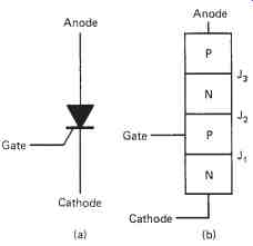
FIG. 2. SCR crystal: (a) symbol; (b) structure
To turn off a conductive SCR, it is necessary to momentarily remove or reduce the anode-cathode voltage. The device will then remain in this state until the anode, cathode, and gate are forward biased again. With ac applied to an SCR, it will automatically turn off during one alternation of the input.
Control is achieved by altering the turn-on time during the conductive or "on" alter nation.
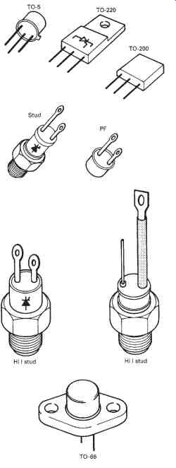
FIG. 3. Representative SCR packages
SCR I-V Characteristics
The current-voltage characteristics of an SCR tell much about its operation. The I-V characteristic curve of FIG. 4 shows that an SCR has two conduction states. Quadrant I shows conduction in the forward direction, which shows how conduction occurs when the forward breakover voltage (VBO) is exceeded. Note that the curve returns to approximately zero after the VBO has been exceeded. When conduction occurs, the internal resistance of the SCR drops to a minute value similar to that of a forward-biased silicon diode. The conduction cur rent (IAK) must be limited by an external resistor. This current, however, must be great enough to maintain conduction when it starts. The holding current or IH level must be exceeded for this to take place. Note that the IH level is just above the knee of the IAK curve after it returns to the center.
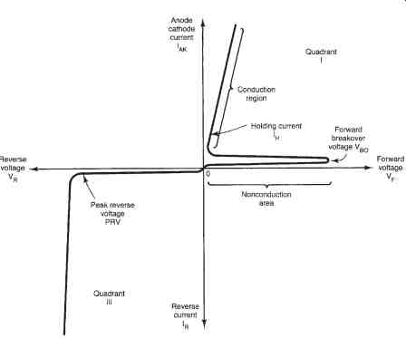
FIG. 4. I-V characteristics of an SCR
Quadrant III of the I FIG. 4. I-V characteristics of an SCR-V characteristic curve shows the reverse break down condition of operation. This characteristic of an SCR is similar to that of a silicon diode. Conduction occurs when the peak reverse voltage (PRV) value is reached. Normally, an SCR would be permanently damaged if the PRV is exceeded. Today, SCRs have PRV ratings of 25 to 2000 V.
For an SCR to be used as a power control device, the forward VBO must be altered. Changes in gate current will cause a decrease in the VBO. This occurs when the gate is for-ward biased. An increase in IG will cause a large reduction in the forward VBO. An enlargement of quadrant I of the I-V characteristics is shown in FIG. 9, which also shows how different values of IG change the VBO. With 0 IG it takes a VBO o of 400 V to produce conduction. An increase in IG reduces this quite significantly. With 7 mA of IG the SCR conducts as a forward-biased silicon diode. Lesser values of IG will cause an increase in the VBO needed to produce conduction.
The gate current characteristic of an SCR shows an important electrical operating condition. For any value of IG there is a specific VBO that must be reached before conduction can occur, which means that an SCR can be turned on when a proper combination of IG and VBO is achieved.
This characteristic is used to control conduction when the SCR is used as a power control device.
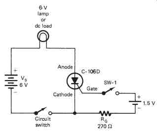
FIG. 5. DC power control switch
DC Power Control with SCRs
When an SCR is used as a power control device, it responds primarily as a switch. When the applied source voltage is be-low the forward break down voltage, control is achieved by increasing the gate current. Gate cur rent is usually made large enough to ensure that the SCR will turn on at the proper time. Gate current is generally applied for only a short time. In many applications this may be in the form of a short-duration pulse. Continuous IG is not needed to trigger an SCR into conduction. After conduction occurs, the SCR will not turn off until the IAK drops to zero.
FIG. 5 shows an SCR used as a dc power control switch. In this type of circuit, a rather high load current is controlled by a small gate cur rent. Note that the electrical power source (VS) is controlled by the SCR. The polarity of VS must forward bias the SCR, which is achieved by making the anode positive and the cathode negative.
When the circuit switch is turned on initially, the load is not energized. In this situation the VBo is in excess of the VS voltage. Power control is achieved by turning on SW-1 which forward biases the gate. If a suitable value of IG occurs, it will lower the VBO and turn on the SCR. The IG can be removed and the SCR will remain in conduction. To turn the circuit off, momentarily open the circuit switch. With the circuit switch on again, the SCR will remain in the off state. It will go into conduction again by closing SW-1.
DC power control applications of the SCR require two switches to achieve control, but this application of the SCR is not practical. The circuit switch would need to be capable of handling the load current. The gate switch could be rated at an extremely small value. If several switches were needed to control the load from different locations, this circuit would be more practical. More practical dc power circuits can be achieved by adding a number of additional components. FIG. 6 shows a dc power control circuit with one SCR being controlled by a second SCR. SCR1 would control the dc load current. SCR2 controls the conduction of SCR1.
In this circuit, switching of a high-current load is achieved with two small, low-current switches. SCR1 would be rated to handle the load current.
SCR2 could have a rather small current-handling capacity. Control of this type could probably be achieved for less than a circuit employing a large electrical contactor switch.
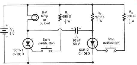
FIG. 6. DC power control circuit
Operation of the dc control circuit of FIG. 6 is based on the conduction of SCR1 and SCR2. To turn on the load, the "start" pushbutton is momentarily closed, and thus forward biases the gate of SCR1. The VBO is reduced and SCR1 goes into conduction. The load current latches SCR1 in its conduction state. This action also causes C1 to charge to the indicated polarity. The load will remain energized as long as power is supplied to the circuit.
Turn-off of SCR1 is achieved by pushing the stop button, which momentarily applies IG to SCR2 and causes it to be conductive. The charge on C1 is momentarily applied to the anode and cathode of SCR1, which reduces the IAK of SCR1 and causes it to turn off. The circuit will remain in the off state until it is energized by the start button. An SCR power circuit of this type can be controlled with two small pushbuttons. As a rule, control of this type would be more reliable and less expensive than a dc electrical contactor circuit.
AC Power Control with SCRs
Ac electrical power control applications of an SCR are common. As a general rule, control is easy to achieve. The SCR automatically turns off during one alternation of the ac input and thus eliminates the turn off problem with the dc circuit. The load of an ac circuit will see current only for one alternation of the input cycle. In effect, an SCR power control circuit has half-wave output. The conduction time of an alternation can be varied with an SCR circuit. We can have variable output through this method of control.
A simple SCR power control switch is shown in FIG. 7. Connected in this manner, conduction of ac will only occur when the anode is positive and the cathode negative. Conduction will not occur until SW-1 is closed. When this takes place, there is gate current. The value of IG lowers the VBO to where the SCR becomes conductive. RG of the gate circuit limits the peak value of IG. Diode (D1) prevents reverse voltage from being applied between the gate and cathode of the SCR. With SW-1 closed, the gate will be forward biased for only one alternation, which is the same alternation that forward biases the anode and cathode. With a suitable value of IG and correct anode-cathode voltage ( V AK), the SCR will become conductive.
The ac power control switch of FIG. 7 is designed primarily to take the place of a mechanical switch. With a circuit of this type, it is possible to control a rather large amount of electrical power with a rather small switch. Control of this type is reliable. The switch does not have contacts that spark and arc when changes in load current occur. Control of this type, however, is only an on-off function. SCRs are widely used to control the amount of electrical power supplied to a load device. Circuits of this type respond well to 60 Hz ac.
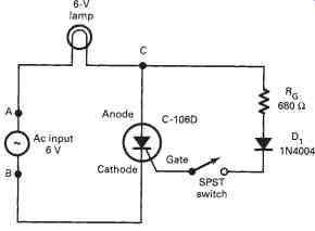
FIG. 7. SCR power control switch
TRIAC POWER CONTROL
Ac power control can be achieved with a device that switches on and off during each alternation. Control of this type is accomplished with a special solid-state device known as a triac. This device is described as a three terminal ac switch. Gate current is used to control the conduction time of either alternation of the ac waveform. In a sense, the triac is the equivalent of two reverse-connected SCRs feeding a common load device.
A triac is classified as a gate-controlled ac switch. For the positive alternation it responds as a PNPN device. An alternate crystal structure of the NPNP type is used for the negative alternation. Each crystal structure is triggered into conduction by the same gate connection. The gate has a dual-polarity triggering capability.
Triac Construction
A triac is a solid-state device made of two different four-layer crystal structures connected between two terminals. We do not generally use the terms anode and cathode to describe these terminals. For one alternation they would be the anode and cathode. For the other alternation they would respond as the cathode and anode. It is common practice therefore to use the terms main 1 and main 2 or terminal 1 and terminal 2 to describe these leads. The third connection is the gate. This lead determines when the device switches from its off to its on state. The gate G will normally go into conduction when it is forward biased, and is usually based on the polarity of terminal 1. If T1 is negative, G must be positive. When T1 is positive, the gate must be negative. This means that ac volt-age must be applied to the gate to cause conduction during each alternation of the T1 T2 voltage. The schematic symbol and the crystal structure of a triac are shown in FIG. 8. Notice the junction of the crystal structure simplification. Looking from T1 to T2, the structure involves crystals N1, P1, N2, and P2. The gate is used to bias P1. This is primarily the same as an SCR with T1 serving as the cathode and T2 the anode.
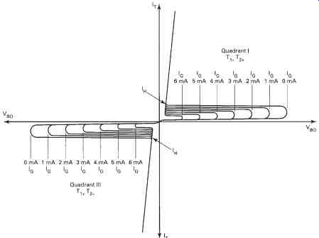
FIG. 8. I-V characteristics of a triac.
Looking at the crystal structure from T2 to T1, it is N3, P2, N2, and P1. The gate is used to bias N4 for control in this direction, which is similar to the structure of an SCR in this direction. Notice that T1, T2, and G are all connected to two pieces of crystal. Conduction will take place only through the crystal polarity that is forward biased. When T1 is negative, for example, N1 is forward biased and P1 is reverse biased. Terminal selection by bias polarity is the same for all three terminals.
The schematic symbol of the triac is representative of reverse-connected diodes. The gate is connected to the same end as T1, which is an important consideration when connecting the triac into a circuit. The gate is normally forward biased with respect to T1.
When ac is applied to a triac, conduction can occur for each alternation, but T1 and T2 must be properly biased with respect to the gate. For ward conduction occurs when T1 is negative, the gate (G) is positive, and T2 is positive. Reverse conduction occurs when T1 is positive, G is negative, and T2 is negative. Conduction in either direction is similar to that of the SCR.
Triac I-V Characteristics
The I-V characteristic of a triac shows how it responds to forward and reverse voltages. FIG. 8 is a typical triac I-V characteristic. Note that conduction occurs in quadrants I and III. The conduction in each quadrant is primarily the same. With 0 IG, the breakover voltage is usually quite high. When breakover occurs, the curve quickly returns to the center. This shows a drop in the internal resistance of the device when conduction occurs. Conduction current must be limited by an external resistor. The holding current or IH of a triac occurs just above the knee of the IT curve. IH must be attained or the device will not latch during a specific alternation.
Quadrant III is normally the same as quadrant I and thus ensures that operation will be the same for each alter-nation. Because the triac is conductive during quadrant III, it does not have a peak reverse voltage rating. It does, however, have a maximum reverse conduction current value the same as the maximum forward conduction value. The conduction characteristics of quadrant III are mirror images of quadrant I.
Triac Applications
Triacs are used primarily to achieve ac power control. In this application the triac responds primarily as a switch. Through normal switching action, it is possible to control the ac energy source for a portion of each alternation. If conduction occurs for both alternations of a complete sine wave, 100% of the power is delivered to the load device. Conduction for half of each alternation permits 50% control. If conduction is for one fourth of each alternation, the load receives less than 25% of its normal power. It is possible through this device to control conduction for the en tire sine wave, which means that a triac is capable of controlling from 0% to 100% of the electrical power supplied to a load device. Control of this type is efficient as practically no power is consumed by the triac while per forming its control function.
Static Switching. The use of a triac as a static switch is primarily an on-off function. Control of this type has a number of advantages over mechanical load switching. A high-current energy source can be controlled with a very small switch. No contact bounce occurs with solid-state switching which generally reduces arcing and switch contact destruction.
Control of this type is rather easy to achieve. Only a small number of parts are needed for a triac switch.
Two rather simple triac switching applications are shown in FIG. 9. The circuit in FIG. 9(a) shows the load being controlled by an SPST switch. When the switch is closed, ac is applied to the gate. Resistor R1 limits the gate current to a reasonable operating value. With ac applied to the gate, conduction occurs for the entire sine wave. The gate of this circuit requires only a few milliamperes of current to turn on the triac.
Practically any small switch could be used to control a rather large load current.
The circuit of FIG. 9(b) is considered to be a three-position switch. In position 1, the gate is open and the power is off. In position 2, gate current flows for only one alternation. The load receives power during one alternation, which is the half-power operating position. In position 3, gate cur-rent flows for both alternations. The load receives full ac power in this position.
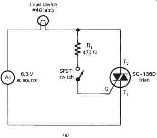
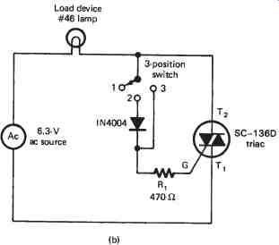
FIG. 9. Triac switching circuits: (a) static triac switch; (b) three-position
static switch
Start-stop Triac Control
Some electrical power circuits are controlled by two push-buttons or start-stop switches. Control of this type begins by momentarily pushing the start button. Operation then continues after releasing the depressed button. To turn off the circuit, a stop button is momentarily pushed. The circuit then resets itself in preparation for the next starting operation. Control of this type is widely used in motor control applications and for lighting circuits. A triac can be adapted for this type of power control.
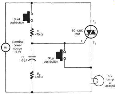
A start-stop triac control circuit is shown in FIG. 10. When electrical power is first applied to this circuit, the triac is in its nonconductive state. The load does not receive any power for operation. All the supply voltage appears across the triac because of its high resistance. No voltage appears across the RC circuit, the gate, or the load device initially.
To energize the load device, the start pushbutton is momentarily pressed. C1 charges immediately through R1 and R2, which in turn causes IG to flow into the gate. The VBO of the triac is lowered and it goes into conduction. Voltage now appears across the load, R2-C1, and the gate. The charging current of R2-C1 and the gate continue and are at peak value when the source voltage alternation changes. The gate then retriggers the triac for the next alternation. C1 is recharged through the gate and R2. The next alternation change causes IG to again flow for retriggering of the triac.
The load receives full power from the source. The process will continue into conduction as long as power is supplied by the source. To turn off the circuit, the stop button is momentarily depressed. This action immediately bypasses the gate current around the triac. With no gate current, the triac will not latch during the alternation change. As a result, C1 cannot be recharged. The triac will then remain off for each succeeding alternation change. Conduction can be restored only by pressing the start button. This circuit is a triac equivalent of the ac motor electrical contactor.
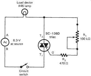
FIG. 11. Variable lamp control
Triac Variable Power Control
The triac is widely used as a variable ac power control device. Control of this type is generally called full-wave control. Full wave refers to the fact that both alternations of a sine wave are being controlled. Variable control of this type is achieved by delaying the start of each alternation.
This process is similar to that of the SCR. The primary difference is that tri ac conduction applies to the entire sine wave. For this to be accomplished, ac must be applied to both the gate and the conduction terminals.
Variable ac power control can be achieved rather easily when the source is low voltage. FIG. 11 shows a simple low-voltage variable lamp control circuit. Note that the gate current of this circuit is controlled by a potentiometer. Connected in this manner, adjustment of R1 deter mines the value of gate current for each alternation.
Conduction of a triac is controlled by the polarity of T1 and T2 with respect to the gate voltage. For the positive alternation, assume that point A is positive and B is negative, thus causing a +T2, a -T1, and a +IG.. The value of the circuit gate current is determined by the resistance of R1 and R2.
For a high-resistance setting of R1, the triac may not go into conduction at all. For a smaller resistance value, conduction can be delayed in varying amounts. Generally, conduction delay will occur only during the first 90° of the alternation. If conduction does not occur by this time, it will be off for the last 90° of the alternation.
Variable control of the same type also occurs during the negative alternation. For this alternation, point A is negative and point B is positive, thus causing a - T2, a +T1, and a -IG. Gate current will flow and cause conduction during this alternation. The resistance setting of R1 influences IG in the same manner as it did for the positive alternation. Both alternations will therefore be controlled equally. Variable control of this type applies to only 50% of the source volt-age. If conduction does not occur in the first 90% of an alternation, no control will be achieved.
DIAC POWER CONTROL
A diac is a special diode that can be triggered into conduction by voltage. This device is classified as a bidirectional trigger diode, meaning that it can be triggered into conduction in either direction. The word diac is derived from "diode for ac." This device is used primarily to control the gate current of a triac. It will go into conduction during either the positive or the negative alternation. Conduction is achieved by simply exceeding the breakover voltage.
FIG. 12 shows the crystal structure, schematic symbol, and I-V characteristics of a diac. Note that the crystal is similar to that of a transistor without a base. The N1 and N2 crystals are primarily the same in all respects. A diac will therefore go into conduction at precisely the same negative or positive voltage value. Conduction occurs only when in-put voltage exceeds the breakover voltage. A rather limited number of diacs are available today. The one shown here has a minimum VBO of 28 V. This particular device is a standard trigger for triac control. Note that the volt age across the diac decreases in value after it has been triggered.
ELECTRONIC CONTROL CONSIDERATIONS
Electronic power control with an SCR or a triac is efficient when used properly. These devices are, however, attached directly to the ac power line. Severe damage to a load device and a potential electrical hazard may occur if this method of control is connected improperly. As a general rule, SCR and triac control should not be attempted for ac-only equipment such as fluorescent lamps, TV receivers, induction motors, and other transformer-operated devices.
SCR and triac control can be used effectively to control resistive loads such as incandescent lamps, soldering irons or pencils, heating devices and electric blankets. It is also safe to use this type of control for universal motors. This type of motor is commonly used in portable power tools and some small appliances such as portable drills, saws, sanders, electric knives, and mixers. When in doubt about a particular device, check the manufacturer's instruction manual. It is also important that the wattage rating of the load not exceed the wattage of the control device. Wattage ratings are nearly always marked on the device.
