AMAZON multi-meters discounts AMAZON oscilloscope discounts
Test instruments are vital to electric motor maintenance and troubleshooting. Lost production makes reactive maintenance ("wait until it smokes") much too costly. Proper application of the right instrument, combined with a good understanding of electric motors, results in quick, accurate decisions.
A reputable organization such as the Electrical Apparatus Service Association (EASA), a worldwide organization of electric motor repair centers, should be consulted before investing in expensive test equipment. An instrument salesperson must be able to show the Institute of Electrical and Electronics Engineers (IEEE) or National Electrical Manufacturers Association (NEMA) standards that verify the values, specifications, and pass/fail limits that are failure indicators. Many of the so-called limits don't exist.
Services that require special training, such as balancing, surge testing, and particle analysis, are offered by electric motor service centers and bearing companies. Many industries outsource these services rather than train their own personnel.
The first part of this section covers the first instruments used to troubleshoot a motor problem. The second part is on instruments and tests that are sometimes outsourced.
Instruments for Initial Testing
Instruments for initial testing include
• Voltmeter (with infrared temperature capability)
• Ammeter (clamp-on)
• Ohmmeter (multimeter with built-in infrared thermometer)
• Micro-ohmmeter
• Tachometer (with vibration meter)
• Megohmmeter (megger)
• Infrared gun
• Stethoscope
Voltmeter
The voltmeter (Fig. 8.1) is usually the first troubleshooting instrument used. Even if the problem is obvious, such as a smoking motor, checking the voltage may reveal the reason for a motor's failure. In addition, it verifies that the power is off (for safety concerns).
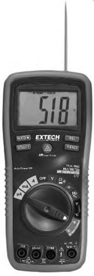
FIGURE 8.1 The voltmeter/infrared thermometer is the first instrument used
when troubleshooting. EXTECH Instruments.
A voltmeter tests for line-to-line comparison at the motor's disconnect switch and at the motor's leads (preferably under load). It tests for voltage unbalance (unbalance should not be over 1 percent), an open line, and high or low voltage.
Voltage unbalance will cause a motor to run hot-even if it is not fully loaded-and eventually fail. It's caused by faulty connections, faulty incoming power, and severe upstream load unbalance. A blown fuse will show a voltage reading across it.
This voltmeter has infrared temperature capability. Infrared should be used in the initial test. Check the pulley for heat caused by excessive slippage/worn grooves, shaft end bearing journal, and the stator. This information is valuable in determining the breakdown cause.
Three-phase motors won't start when there's an open line. Their power drops to about half if they are running when the line opens. The open line may" show a voltage reading because voltage is fed back through loads that are online. It can be verified by opening the suspected line. Remove the fuse or open the disconnect. There will be no change in the (load side) voltage reading if this is the open line.
High voltage (above 10 percent of the motor's rating) can be caused by power factor correcting capacitors that are online when they aren't needed.
Power suppliers sometimes raise the voltage to compensate for voltage drop caused by a maximum load. High voltage develops when the load is switched off.
Low voltage causes include inadequate wire size (too much voltage drop after load is applied), undersized transformer, wrong voltage (more than 10 percent below the motor's rating), severe load unbalance, and overloaded main feeder circuit.
AC and DC voltmeters for troubleshooting DC machines are covered in Section 2. The voltmeter compares the voltage drop across coils (shunt field, series field, and interpoles), reads from brush to commutator (contact drop), checks interpole polarity, checks for continuity between shunt and series field coils, and measures bar-to-bar voltage.
Clamp-on Ammeter
An ammeter (Fig. 8.2) is used on a motor that runs hot and is noisy (excluding bearing noise), and on a motor that starts more slowly than normal. It also tests for line-to-line current unbalance.
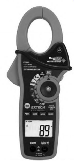
FIGURE 8.2 The clamp-on ammeter (with ohmmeter function) gives amperes without
touching any live conductors. EXTECH Instruments.
Causes of high ampere reading include overload, faulty bearings, shorted winding, open winding, faulty rotor, and voltage problems (covered under the preceding section, "Voltmeter").
A digital ammeter set on high-ampere lockout can be used to estimate locked rotor current (see "Code Letter" in Section 5). The ammeter should always be used on a replacement motor following installation. The best place to take an ampere reading is at the motor leads, under full load.
Ohmmeter
An ohmmeter should never be used when there is a voltage potential in the circuit. Line voltage can destroy most ohm meters.
The first test (after determining that the power is off) is to test the motor at the disconnect for a ground. If there is a ground, no further testing is necessary from that point. The next step is to disconnect the motor to verify- that the ground is in the motor.
The ohmmeter has its own power source (batteries) and uses very low current. Insulation-piercing needle probes can be used because of the instrument's low current (Fig. 8.3). However, an ohmmeter can destroy some electronic components if applied incorrectly.
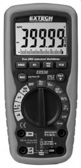
FIGURE 8.3 A multimeter with an ohmmeter function. EXTECH Instruments.
An ohmmeter is used to test a motor's insulation between its winding and its frame. It will detect conducting contaminants without damaging the insulation. It should always be used before applying a high-potential tester or any type of high-voltage testing equipment.
Other uses within its size range include comparison-testing of individual coils or identical circuits; checking an armature for shorted, open, or grounded circuits; and testing a squirrel cage rotor for open bars. Procedures for these tests are described in other parts of this guide.
When a good capacitor is tested, the ohmmeter shows a low-resistance reading, which rises slowly until the capacitor is charged. This test indicates the capacitor has capacitance. However, it doesn't give the amount of capacitance. No reading means that the capacitor is open. A steady low- resistance reading indicates that it's shorted.
An ohmmeter's test limit for three-phase induction motors is about 10 horsepower. Larger motors can be tested with a micro-ohmmeter.
Micro-ohmmeter
The micro-ohmmeter can test very low resistance. The instrument uses up to 5 amperes (supplied by batteries or a single-phase source). The micro-ohmmeter in Fig. 8.4 measures down to 0.01 milliohm.
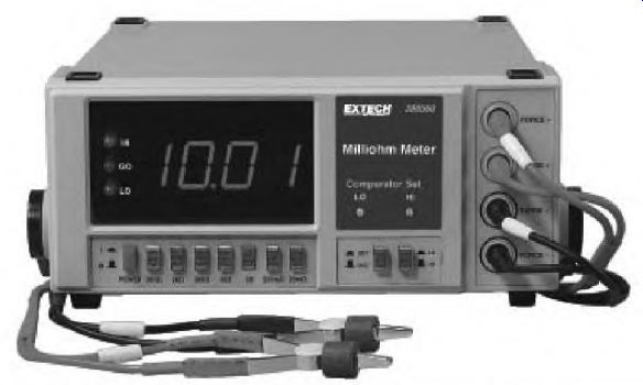
FIGURE 8.4 A micro-ohmmeter designed for low-resistance testing. EXTECH Instruments.
Temperature index is an important factor in calculating low resistance and must be used for exact measurements.
When low resistance is being tested, the test probes must have a secure connection to the circuit conductors.
The micro-ohmmeter can be used in the following tests:
• Polarization index
• Testing of large three-phase motor windings, internal connections, and rotors
• Transformer windings
• Bus bar connections and circuit breakers
• Lead connections (contaminant between the lugs)
• Low-resistance coils (interpoles, series field coils, compensating windings)
• Large armature circuitry (riser weld integrity, equalizer connections, and coil resistance comparison)
Tachometer
Handheld tachometers need a piece of tape on the shaft for a reference point. The shaft key will work, although it may have to be filed or scraped clean. Two reference spots will double the reading. Like any test instrument, it takes some practice to develop confidence in it.
A hot-running motor should be tested with a noncontact type of tachometer (Fig. 8.5) before using electrical test instruments. All induction motors get hot when they run more slowly than their nameplate speed.
(Loaded RPM shouldn't be lower than the nameplate RPM.) When a motor's nameplate RPM is close to synchronous speed (less than 1 percent), reduced RPM becomes very critical. Low-slip induction motors (design A and most high-efficiency motors) have a substantial increase in amperes when loaded only a few RPM under their nameplate rating.
Excessive heat shortens insulation life and bearing life.
Several factors cause a motor to run more slowly than the nameplate RPM. These include overload, rotor problems, operating on low voltage, unbalanced voltage, a shorted or open winding, and an open supply line (single-phased).
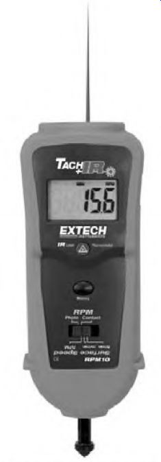
FIGURE 8.5 A noncontact type of tachometer (used with nameplate RPM) can quickly
tell if a motor is overloaded. This model has an infrared thermometer feature.
EXTECH Instruments.
Megohmmeter
The megohmmeter (megger) is used to test the insulation between the winding and the core of a motor (Fig. 8.6). It can also be used to test the insulation between windings, such as with the series and shunt field in a DC motor. It can be used for a phase-to-phase test on three-phase motors that have Wye-delta and 12-lead connections. (Phases can be isolated with these connections.)
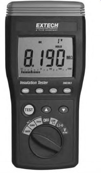
FIGURE 8.6 The megohmmeter. EXTECH Instruments.
The megohmmeter produces a DC voltage (500 to 5000 volts) with very low amperes. The test involves time-up to 3 minutes. During this time, the capacitance of the machine is charged.
When two conductors are separated by insulation, they" form a crude capacitor (see Section 4). The two conductors are the plates of the capacitor.
The conductors (plates) are separated by the slot insulation, which is the dielectric.
The winding in a motor has a large area when viewed as a capacitor plate. The slot area of an AC motor (and the pole iron of a DC motor) forms a sizable plate area.
The amount of time it takes to charge the capacitance to full value depends on the amount of capacitance the machine has, and the power output of the megger. There will be a small amount of leakage (measured in megohms) when the full charge is reached. This value should not be less than 50 megohms. (One megohm was originally acceptable.) A new or rewound motor will test infinity.
At the start of the megohmmeter test there's an inrush of current that charges the capacitance of the motor. When the test is completed, a charge may remain between the winding and the motor's frame. For personal safety, the leads should be grounded to the motor's frame to discharge the voltage (after testing).
The megohmmeter is also used in the polarization index test. The procedure is found in the upcoming section "Instruments for In-depth Testing and Scheduled Maintenance."
Infrared Gun
An infrared gun (Fig. 8.7) can detect the temperature of a device without having physical contact. This is useful for checking (or comparing) the temperature of connections, especially high-voltage connections.
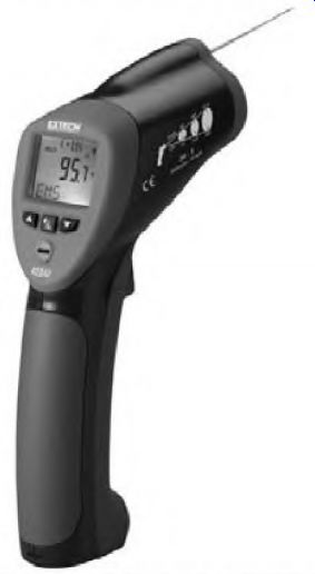
FIGURE 8.7 The infrared gun is a noncontact instrument for detecting temperature-related
problems. EXT ECU Instruments.
A very common, destructive problem for motors is the high-resistance (hot) connection. Every time a motor starts, high inrush amperes (sometimes over 500 percent of nameplate amps) will stress all the motor circuit's connections. Connections should be checked with an infrared thermometer routinely, especially if the motor starts frequently. A hot connection should be checked for oxidation, and cleaned or replaced if necessary.
High temperature usually indicates a motor problem. (Windings or bearings often get hot just before they fail.) The temperatures of like components in an open motor, such as individual brushes or coils, can be compared quickly and safely.
Other uses for this instrument are to check liquid level in tanks; check above-normal heat in pulleys and belts, couplings, gearboxes, pillow block bearings, and (hot) conduit; and check anything hot enough to cause injury.
Some infrared guns have information storage capability and are compatible with computer software programs. The data can be easily referenced when abnormal operation is suspected.
Stethoscope
A stethoscope is used to pinpoint noise sources. Early detection of bearing failure can be done with this instrument. The electronic model (Fig. 8.8) will record information for comparison and trending. It also allows personal observation. The stethoscope also checks for leak detection, liquid flow or no flow, and arcing.
Instruments for In-depth
Testing and Scheduled Maintenance
Instruments for in-depth testing and scheduled maintenance include
• Surge tester
• Rotor test
• Polarization index test
• Step voltage test
• High-potential test (hi-pot)
• Power quality test instruments
• Power factor meter
• Vibration monitoring sensors
• Laser alignment
• Particle analysis
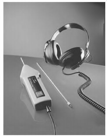
FIGURE 8.8 A stethoscope used to pinpoint problems. SKF USA Inc.
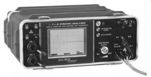
FIGURE 8.9 A surge tester capable of comparison and turn-to-turn voltage stress
testing. Electron! Instruments.
Surge Tester
The surge tester (Fig. 8.9) has the capability of detecting a turn-to-turn fault in individual coils before it becomes an actual breakdown. It can also compare two identical circuits during this test. Other test instruments can compare identical circuits as well, but can't check the turn-to-turn insulation. EASA estimates that 80 percent of insulation breakdowns start as a turn-to-turn fault.
During the test procedure, this instrument also performs a low-resistance test that (in rare cases) will reveal problems that the surge comparison test misses. One example is a poor connection in a multiple-circuit winding.
The faulty connection wasn't revealed because the surge test is based on inductance. (When one wire of a multiple wire, winding conductor [for example, when four #12 wires are used instead of one #6] is open, the inductance can be the same, but the resistance is less.) The surge tester uses up to 10 amperes in its resistance test. The results are printed in hard copy for further review.
The surge tester is often used in predictive maintenance programs. The test unit can be applied at the motor's disconnect, where it will test both the motor and its supply lines. It's not always used during the initial test procedure because of its weight. It is often used to confirm problems that are hard to identify (before a motor is replaced). The surge tester uses a precisely controlled spike of voltage on the windings. The duration of the spike is so short that it doesn't damage the insulation. The power of the instrument is so well controlled that an arc won't cause carbon tracking, unless the test isn't stopped soon enough.
When a high voltage is impressed turn to turn, any weak spot in the insulation will arc. The test should be stopped as soon as a fault is detected, to prevent further damage. A serious problem has been identified, and the motor can be operated until it's convenient to replace it. There are numerous cases where this tester has saved thousands of dollars in lost production.
Comparison-testing is done with the surge tester's dual-trace (signal) oscilloscope (Fig. 8.10). Two identical windings are tested at the same time.
Each signal records the inductance of its respective winding. Any difference in inductance will separate the two signals, indicating a problem. If the signal scrambles, the test is stopped immediately. A scrambled signal indicates arcing caused by a weak spot in the insulation. If the weak spot is visible, it can sometimes he repaired.
Different-shaped signals identify problems such as a turn-to-turn short, phase-to-phase short, wrong connection (internally or externally), and grounded turns.
Rotor Test
With the Electrom rotor bar clamp, (Fig. 8.11) a motor's rotor can be tested in place. Open rotor bars described in Section 6 can be detected without disassembling the motor.
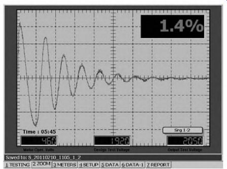
FIGURE 8.10 The signal on the surge tester's dual-trace oscilloscope shows
that the two windings being tested have no problem. The motor is being tested
from its disconnect. Electrom Instruments.
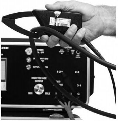
FIGURE 8.11 Rotor clamp being used to test for rotor problems while the motor
is running. Electrom Instruments.
DC armatures can be tested using a special attachment shown in Fig. 8.12. Large armatures can also be tested, as well as those with equalizer connections.
Polarization Index Test with a Megohmmeter
The polarization index test is done to determine the condition of the insulation that protects the coils. Insulation being tested is located between the coil wire and any path to the frame. (This includes air over the end turns of the coils.) The test is dependable for only form-wound or taped coils that have no wire exposed to air (such as random-wound motors). The random- wound coils are seldom taped and sealed, making the test easily corrupted by changing conditions such as high humidity or conducting dirt.
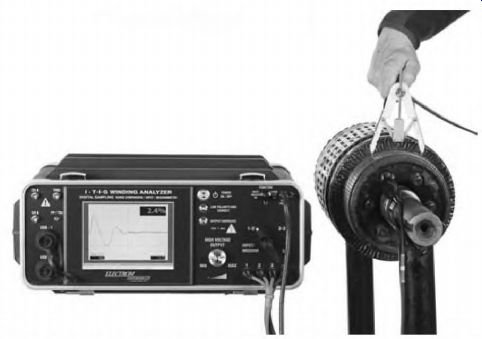
FIGURE 8.12 Adapter used to test armature windings with a surge tester.
Electrom Instruments.
In the polarization index test described below, it is assumed that the motor's insulation is not made of epoxy resin or one of the many polymer products. The test doesn't work on these materials.
Many industries don't use this test because it's hard to identify the insulation varieties that invalidate the test. The majority of motors in service are random wound and, as explained above, can't be reliably tested due to the many corrupting variables.
The polarization index test is a trending procedure that documents the degradation of insulation over a timed series of tests. The tests are done at 6- to 12-month intervals. A reading is taken at 1 minute and again at 10 minutes from the time the voltage is applied. The 10-minute reading is divided by the 1-minute reading to get the polarization index. The result should be between 2 and 5. A reading below 2 indicates conducting dirt or moisture. If the result is above 5, the insulation is crystallized (brittle) and could fail.
During the test, the molecules in the insulation are becoming aligned.
Current flows and resistance is lower during the alignment of the molecules, and decreases to a lesser value at 10 minutes. The 10-minute value has higher resistance than the 1-minute value.
The motor has to be offline for at least an hour before the polarization index test is performed. Energizing the winding with any type of voltage source will align the free molecules and cause an invalid test. It is good practice to ground the motor leads to the frame for an hour before testing.
As insulation ages, it becomes brittle (crystallized) and there are fewer free molecules. This is why it takes less time to align the free molecules.
The test result number becomes higher as the aging progress goes on. At some age, the time it takes to polarize the insulation gives a result greater than 5. At this time the insulation is so brittle that cracks form. If there are conducting contaminants present, the current flows, carbon forms, and there is complete insulation breakdown.
Step Voltage Test
The step voltage test is done with an instrument called a winding analyzer (Fig. 8.13a). The machine is computer-compatible and can give a printout of the test results. The printouts show the voltage and current of each step (Fig. 8.13b).
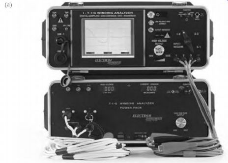
FIGURE 8.13 (a) The winding analyzer used in the step voltage test.
Electrom Instruments.
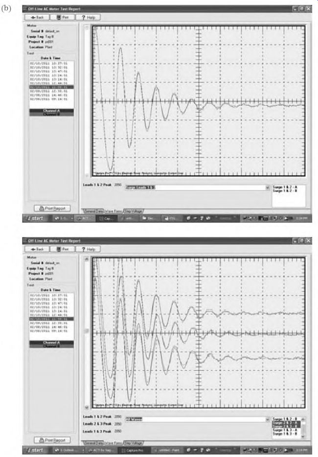
FIGURE 8.13 (continued) (b) Printouts of the step voltage test. Electrom Instruments.
The test measures the current leakage (caused by contaminants) from the motor's winding to its frame. It is a trending procedure similar to the polarization index test. However, unlike the polarization index test, it works on any type of insulation. It's much more precise than a megohmmeter and can store information for future comparison.
The test can be done at the control terminals or at the motor's junction box. (Control components that can be damaged should be isolated from the test.) Voltage should be raised slowly to its test value to avoid damaging spikes. The leads should be grounded to the frame after the test is completed.
The test procedure is as follows: DC voltage is applied in steps, starting with 500 volts, then 1000 volts, etc., up to the motor's high-potential test value: 2 x rated voltage + 1000 volts.
Each voltage value is applied for 1 minute. The machine then records the voltage and current of each step. There is an inrush of current when the voltage is applied. This current charges the capacitor effect of the winding and polarizes the insulation. (After 1 minute, the current stabilizes to its leakage value.) Leakage current rises as the voltage increases. A sharp increase over the previous test indicates the winding should be cleaned.
High-Potential Test
The high-potential (hi-pot) test is done to stress the phase-to-ground (slot) insulation. Always use an ohmmeter before using the hi-pot test (Fig. 8.14). The windings should read at least 50 megohms to the frame before using the hi-pot. Dirty' or wet windings should be cleaned and dried before the hi-pot test. If DC voltage is used, it should be 1.4 times the AC values.
Accepted AC test voltage for high-potential testing is as follows:
• New windings: 2 x rated voltage + 1000 volts for 1 minute
• Small motors rated 250 volts or less: 1000 volts for 1 minute
These variations of the above limits are permissible:
• An equivalent test is 1.2 times the above voltages for 1 second.
• The above voltages x 1.6 for 1 minute (if DC voltage is used).
• Old or contaminated windings: 60 percent of the above voltages for the same time.
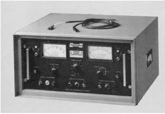
FIGURE 8.14 A high-potential (hi-pot) test instrument. Hipotronics, Inc.
AC should never be used on motors over 150 horsepower. Always ground the motor Leads to the motor frame after each test to discharge voltage stored by the capacitance of the unit. The hi-pot test can be destructive to the insulation.
The test instrument should have an automatic trip feature that shuts it off before damage occurs.
Hermetically sealed refrigeration compressor motors have been damaged when windings were tested while under a vacuum. There are theories as to why this happens, but nothing credible. The best advice is: Don't hi-pot sealed compressor motors.
Power Quality Test Instruments
Power quality test instruments are used when electronic devices are suspected of polluting power supply circuits. Some symptoms of line pollution include motors overheating for no apparent reason, premature winding failure, current-caused ball bearing failure, tripped breakers, hot conduit and/or neutral, and damaging voltage spikes. Figure 8.15 shows an instrument for testing power quality.
Circuits which power large numbers of computers are a problem for supply transformers if no correction is done. Electronic motor controls cause even greater damage to them than the computers because higher amperes are involved. Remedial equipment (reactors, etc.) is essential for preventing equipment breakdown.
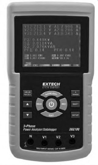
FIGURE 8.15 An instrument for checking a circuit's power factor and power
quality. EXTECH Instruments.
The tests should be done over a long enough period of time to cover all possible conditions.
Identifying and installing remedial equipment is a service that is often outsourced. The use of these test instruments requires specialized training and experience. It is often a one-time service. Safety training for personnel doing these tests is very important because the tests are done with live power.
The meter in Fig. 8.15 is used to determine the phase angle needed for power factor calculating. The consequence of a low power factor can be expensive penalties from the power supplier. A low power factor also affects motors by causing low voltage.
Low power factor is corrected with specially designed capacitors or with synchronous motors. Many industries outsource this procedure because it is normally a one-time service and takes special training. Some electric motor repair centers offer the service. Safety training is very important for personnel doing these tests because they are done with live power lines.
Vibration Sensors
Vibration is the leading cause of bearing failure. It is also an indication of impending bearing failure. Portable instruments work well for spot-checking, but continuously operating machinery should be monitored by attached sensors (Fig. 8.16.)
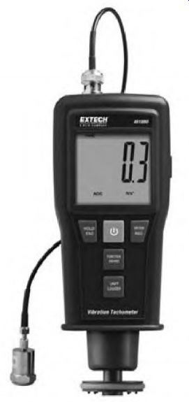
FIGURE 8.16 This instrument will check vibration, and has noncontact tachometer
capability. EXTECH Instruments.
Vibration sensors will automatically give a warning when a preset level of vibration is reached. Corrective action can then be scheduled before catastrophic failure occurs. Electric motor repair centers balance repaired motors in accordance with EASA specifications. Some also offer in-plant machinery balancing. The service is often outsourced because it takes special training.
Laser Alignment
Laser alignment is the most accurate of all alignment methods (Fig. 8.17). It has been used successfully on multilevel shaft applications that require exact precision. It is easy to use and virtually eliminates mistakes that are common with other alignment procedures.
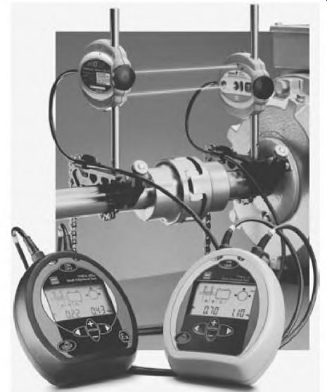
FIGURE 8.17 Laser alignment equipment. SKF USA Inc.
Flexible couplings are designed for a small degree of misalignment.
Experience has shown, however, that vibration will occur unless alignment is nearly perfect.
Particle analysis is a service that will predict machinery failure and is usually outsourced. This early-warning procedure has detected problems missed by" vibration testing. Both oil and grease analysis can be done with this service.
Oil analysis on a regular basis is recommended. It can identify wear particles of each component in a gearbox. If excess wear of a particular component is detected, the service provider will phone or fax the information immediately.
Contaminants will be identified as well as the condition of the lubricant.
This information may indicate the need for more frequent oil changes or a different type of oil (Fig. 8.18).
Particle Analysis
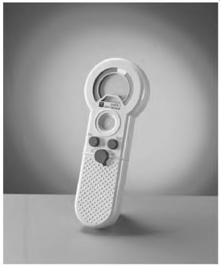
FIGURE 8.18 An oil analysis instrument. SKF USA Inc.
Grease analysis will help pinpoint the cause of frequent ball bearing failure. The type of wear (cutting, corrosion, fatigue, etc.) is identified as well as outside contamination. An analysis of the grease's useful life may indicate a need for more frequent lubrication or for a different grade of grease.
Section 8 Review
1. Test instruments are vital for accurate troubleshooting (67). T F
2. Voltage unbalance will cause immediate motor failure (69). T F
3. The micro-ohmmeter can be used for comparison testing motors larger than 10 horsepower (72). T F
4. A tachometer can be used to determine whether a motor is overloaded (73). T F
5. The main use for the megohmmeter is to test insulation between the winding and the frame of a motor (374-375). T F
6. An infrared gun (like a voltmeter) should be standard equipment in the toolbox (376-377). T F
7. The electronic stethoscope can be used for preventive maintenance (77). T F
8. The surge tester is the only instrument that will reliably stress turn-to- turn insulation (378-379). T F
9. The polarization index test will work on all motors (381-383). T F
10. The polarization index test should be done immediately after a motor has been shut off (83). T F
11. The step voltage test will work on all motors (85). T F
12. The high-potential test voltage should never be applied to a winding when it is set at its full value (385-386). T F
13. The high-potential test is done to check phase-to-phase insulation (85). T F
14. 2 x rated voltage + 1000 volts for one minute is acceptable for all motors (85). T F
15. What are three signs of power quality problems (386-388)?
16. Give two reasons for improving an industry's power factor (386-388).
17. Vibration analysis and balancing are limited to electric motors (388-389). T F
18. Laser alignment is the most reliable method to reduce coupling vibration (389-390). T F
19. Particle analysis can predict bearing and gear problems in gearboxes (90). T F