AMAZON multi-meters discounts AMAZON oscilloscope discounts
Armature Problems
A high percentage of a DC machine's problems occur in the commutator and brushes. Following are some of the test procedures, problems, their causes, and solutions.
Burned Commutator Bars
Burned commutator bars indicate a serious problem, and the machine will need further testing. If two spots appear at 180 electrical degrees from each other (two adjacent brush holders apart on the commutator of most armatures), the armature may have shorted coils. An armature with shorted coils should be rewound.
In some cases, the shorted coil can be cut open and the commutator segments attached to it can be shorted together. (This should be done only in an emergency.)
Dirty Commutator
The mica between the segments has to withstand low voltage, high heat, and extreme mechanical pressure. Because of the heat, this mica has no bonding or sealing agents. It has a linear grain that is flawed with voids.
Individual segments can be replaced in large commutators. In smaller commutators the whole commutator must be replaced.
This same color pattern will appear if the load stops the armature in the same spot every time. If possible, the load should be adjusted to avoid this problem.
Control and Load Problems
Any quick speed change will shorten the life of the commutator and the brushes. (Large motors must have the armature amperes reduced when starting.) A sudden speed increase will damage the commutator as much as across-the-line starting. Sudden load changes will also cause commutator damage.
In some cases, the interpoles won't have time to react, causing the brushes to arc excessively for a short time. (Machines with a large bore have compensating windings to reduce this problem, as explained previously under "Interpoles" in Section 1.)
Brushes
Brushes are classified in the following groups: carbon-graphite, electrographitics, graphites, and metal graphites. Each has its own current- carrying, wear, and filming characteristics. They can be designed for specific requirements such as low voltage/high current, dry conditions, cleaning action for over-filming, and high speed.
Brush Problems
The carbon brush used in a DC machine has a difficult job:
• It must rub on the commutator hard enough to conduct amperes.
• It has to tolerate high heat from friction, ampere flow, and arcing.
• It should cause minimal wear of the commutator material.
A properly designed brush accomplishes all of the above. Original equipment brushes don't always work. Ambient conditions sometimes require a different mix of brush elements. Aftermarket brush companies specialize in solving these problems.
Following are some of the brush and commutator problems and solutions for the DC machine.
Conduction Zone
There is a small area of high current on the face of the brush called the conduction zone (Fig. 2.1). The zone current is part load current and part circulating current.
Carbon conducts better as its temperature goes up. This contributes to the current concentration in a small area. The conduction zone is roughly 10 percent of the total brush face area. (There can be more than one conduction zone on a brush face.) A circulating current is caused by a brush shorting two commutator segments (connected to an energized armature coil). When the brush shorts the coil's two segments, the line current stops, and the magnetism of the coil collapses. This action creates a voltage in the coil.
The brush has joined the segments at the ends of the coil, creating a closed loop circuit. This circuit has low resistance, so a pulse of high current flows in it (Fig. 2.2).
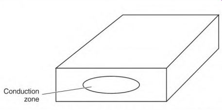
FIGURE 2.1 The conduction zone of a brush, where most of the current flows.
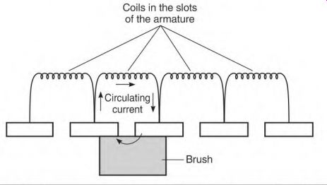
FIGURE 2.2 A discharge current flows in the closed loop when the brush shorts
out the two bars connected to the coils.
The current flows in the opposite direction from what it did when the coil was part of the previous pole. It flows in the same direction as it will when the coil becomes part of the next pole.
The commutator will wear evenly if the conduction zone moves back and forth under the brush. (The zone is moving as it should if sparking at the trailing edge of the brush moves back and forth.) If it doesn't move, or if the circulating current in the zone is too high, the commutator will be damaged.
Two commutator bars are conducting the circulating amperes of the zone and the load amperes. If the circulating current causes excess heat, it's too high and must be reduced. Higher-resistance brushes will reduce the circulating current; however, they also lower the operating amperes.
Brushes that are split into two or more equal parts help control circulating current. The resistance between the brush segments lowers the circulating current without affecting the operating amperes. A split brush also enhances the movement of the conduction zone. The brush sections divide the zone area, leaving each brush section to carry only part of the zone.
Spiral Groove
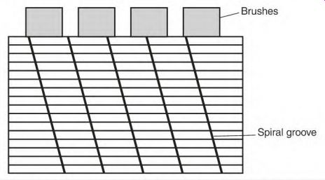
FIGURE 2.3 A spiral groove cut in the bars of a commutator to improve commutation.
A machine is sometimes severely overloaded during its duty cycle, causing commutator damage. A spiral groove cut into the segments of the commutator (Fig. 2.3) will reduce or eliminate this damage and force the conduction zone to move.
The groove should be about twice as wide as the undercut slot of the mica, but not quite as deep. At this depth, the groove will be removed the next time the commutator is reworked on a lathe. (It's easier to cut a new spiral than to deepen it.) The groove should sweep across the face of a brush at least twice per revolution. Spiral grooves are common on slip rings.
Multiple Brushes
If there are multiple brushes in a brush holder, each brush must carry its share of the amperes. Brushes will wear unevenly if they are not carrying equal current.
Open frame machines can be examined with an infrared gun. Take the temperature of each brush while the machine is running. A brush that is hotter than the rest may be carrying more than its share of the amperes.
A brush will arc and get hot if it doesn't have enough spring tension.
Brush Box and Commutator Spacing
A machine's brush boxes should be spaced at an equal distance from the commutator. The spacing should be close enough to keep the brush from chattering. This measurement can be from Vie inch on small machines to Vg inch on large machines. (Some large machines may specify even more space.) A piece of plastic (the right thickness) inserted between the box and commutator works well for setting the box height. Plastic or a similar material won't scratch the commutator.
Distance Between Brushes
The distance between brushes around the commutator must be exactly the same.
Place a strip of paper (adding machine tape) under two adjacent sets of brushes. Pull the paper in the direction of the machine's rotation so that the brushes are against the trailing side of the brush box.
Mark the paper on the trailing side of each brush set. Compare this measurement to the rest of the brushes by inserting the tape under them the same way. A difference of as little as .05 inch can affect commutation.

FIGURE 2.4 Scale used for exact measurement of brush spring tension. Helwig
Carbon Products, Inc.
Brush Holder Alignment
When there are multiple brushes per holder, all brushes should contact the same segments, unless designed otherwise. Misalignment will change the number of coils per pole, causing magnetic unbalance and brush arcing.
Spring Tension
All brushes must press the commutator with the same pressure. Brushes with more spring tension will carry more amperes. A scale designed to weigh spring pressure is available from brush companies (Fig. 2.4).
The recommended spring pressure is as follows:
High-speed turbine rings and soft graphite brushes
Normal speed slip rings
Most industrial motors
Metal graphite
Fractional horsepower
Traction motors
Angled brushes with an angle greater than 25°
2.25-2.75 lb 3.5-4.5 lb 4-5 lb 4.5-5.5 lb 5-8 lb 5-8 lb
Add 1/2 lb
Brush weight must be considered when the machine has large brushes.
The weight of the brush located on top is subtracted from this value, and the weight of the brush on the bottom is added to it. (The tension value of brushes located on the sides of the commutator is the same.)
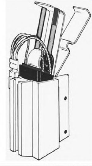
FIGURE 2.5 Continuous pressure brush holder. Helwig Carbon Products, Inc.
Replacing adjustable spring brush boxes with constant spring pressure brush boxes has been very successful (Fig. 2.5).
Brush Shunts
The brush shunt should be well anchored in the brush and show no discoloration from heat. The shunt wire must be large enough to carry the brushes' share of the amperes. (If the wire is discolored from heat, it isn't large enough.) The shunt connection to the brush rigging must be clean and tight. Brushes should be changed before the shunt (or its components) rubs the commutator.
Side Wear
A brush with a poor shunt connection or a shunt wire that is too small will develop side wear on the trailing side of the brush.
The brush box and the shunt are connected to the same conductor. When the brush box conducts some of the amperes, side wear occurs.
The connection between the box and brush isn't solid; therefore normal brush movement will arc away brush material.
Uneven Commutator Segments
Uneven commutator segments will cause brushes to bounce and arc excessively. A faulty segment may lift as the armature turns but not be out of place when standing still. As a commutator heats to normal temperature, thermal growth can distort some segments. Chipped brushes are a symptom of a high segment.
Pressing on the top of the brush with a wood or fiber rod (while the machine is running) will detect uneven commutator segments.
Brush Dusting
Brush dust is a highly conductive contaminant that can cause short circuiting in the machine's circuitry.
Under-loading (low brush current density) is the most common cause of brush dusting; another cause is low humidity. Brush and commutator wear is high without the lubrication that water vapor provides.
Low Load Current
Most brushes should carry 40 to 50 amperes per square inch of brush face area. If the load is lower than this, a different type of brush maybe needed.
Generally speaking, gray brushes will handle under-loading better than black brushes. Some can operate as low as 25 amperes per square inch. Peak amperes for the gray brush, however, would be 80 to 90 amperes per square inch-much lower than the black brush. Gray brushes are softer, hence less commutator wear. Black brushes can handle 110 to 125 peak amperes, but no lower than 40 to 50 amperes per square inch.
An aftermarket brush manufacturer should be consulted to solve brush problems if the machine's manufacturer can't provide information.
Use the following current density formula to determine normal current density. (First, substitute the motor's actual armature amperes for nameplate amperes to see if corrective measures should be taken.)
Current density = nameplate amperes -r 1/2 the brushes x width x thickness
Removing some brushes will lower the total brush area if the machine is underloaded, but the machine's complete duty cycle must be considered.
(First, use the above formula to determine if this will work.) Each brush holder must have the same number of brushes. The removed brushes must not be in line with each other. Figure 2.6 shows the right way to stagger the location of brushes.
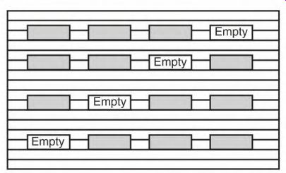
FIGURE 2.6 The correct location of removed brushes when increasing the current
density (of remaining brushes).
Silicone Vapor and Adverse Ambient Conditions
Silicone vapor will cause brush dusting. Silicone grease should never be used on DC machine bearings for this reason. Forced ventilation (using outside air) is recommended when silicone contaminants can't be avoided. Sealing vent covers and replacing gaskets with silicone will cause silicone vapors, and should be avoided.
Adverse ambient conditions affect the commutator and brushes. Air that contains caustic, corrosive, abrasive material or low humidity will shorten the life of the commutator and brushes. Clean air (with controlled humidity) will maximize the machine's running time.
Seating Brushes
Seating brushes to fit the commutator should be done carefully. The brush face must make good contact with all segments under it. Normal operation requires segments of one or more coils to be shorted together under a brush.
If full contact between brush and segments isn't made, the magnetic neutral (explained in the next section) will shift, causing other brushes to arc. The motor will lose power and run hot. This will continue until the brushes are properly seated.
Thin sandpaper is used to do the initial seating (Fig. 2.7). It should be held against the commutator tightly, while rolling the armature or sliding the sandpaper back and forth. The final strokes should be in the direction of rotation. A seating stone can be used for the final seating.
Use a vacuum cleaner during and after this process to remove all residues. Covering the end of the commutator (risers) and the windings (up to the iron) with masking tape is recommended.
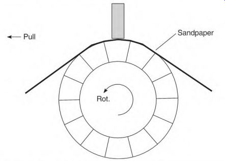
FIGURE 2.7 Seating a brush with sandpaper.
Brushes should move freely in the brush boxes and make good contact with the commutator. The brush face, which contacts the commutator, should be shiny. If any part of the brush face has a flat black color, it isn't making good contact with the commutator.
Neutral Location in the Stator and Armature
The neutral location in the stator is a spot exactly between its poles. It's 90 electrical degrees from each adjacent pole center. (Interpoles are placed in the neutral location.) The neutral spot in an armature iron is the teeth surrounding the slot or slots containing coils (that are shorted by a brush). Whether using the DC kick method (see "Setting Neutral in a Generator") or applying AC to the shunt field, the neutral location is found by checking the commutator's bar-to-bar voltage. (The commutator will have little or no voltage bar to bar in the neutral location.) These bars are located where the voltage transformed into the armature windings from one stator pole is canceled by the voltage transformed by its adjacent stator pole.
When the machine is running, the brushes short the armature coil(s) located in this position. With idle coil(s) in this position, the armature teeth become a pole center, the same as with the pole iron of a shunt field coil (Fig. 2.8).
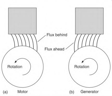
FIGURE 2.8 Lines of force are bent under full load.
Setting Neutral in a Motor
Setting neutral in a motor can be done using a low-voltage voltmeter and 120 volts AC. (The AC voltage should be less than the shunt field's voltage rating.)
Attach the voltmeter to A1 and A2 (armature leads) and apply the AC voltage to F1 and F2 (shunt field leads). Move the brush holder back and forth until the lowest voltage reading is found. Secure the brush holder at this spot. Most machines will not have a 0 voltage spot. (Voltage under 0.5 volt is acceptable.)
Black Band Adjustment
If possible, check the brush arcing at full load. (Further adjusting may be necessary.) The flux (lines of force) will deform as shown in Fig. 2.8.
Move the brush holder one segment at a time against rotation (Fig. 2.8a) until there is the least amount of sparking. This is called the black band method of adjusting the brushes. The term black band doesn't refer to a black band of any kind. Instead, it means the least amount of sparking, as opposed to the light that occurs with excessive sparking along the trailing edge of the brushes.
Setting Neutral in a Generator
To set neutral in a generator using the kick method, use a DC voltage source and a low-voltage voltmeter. The DC voltage should be no higher than the shunt field's rating. Attach the low-voltage voltmeter to A1 and A2. Attach the positive lead of the DC voltage source to F1. Make and break the connection between the negative lead and F2.
As the brush holder is moved, the lowest voltmeter reading will indicate the unloaded neutral spot. Secure the brush holder at this position.
Use the black band method (described in the previous section) for the final setting. If the brushes arc when the generator is loaded, move the brush holder with rotation one segment at a time until arcing is acceptable (Fig. 2.8b).
Restoring Residual Magnetism After Setting Neutral
AC voltage can be used to set the neutral in a generator, but the residual magnetism in the pole iron may become reversed, or demagnetized. If this method is used, apply DC voltage (no higher than the shunt field's rating) for a few minutes, with the positive lead on F1 and the negative lead on F2. This will restore the residual magnetism in the pole iron to the right polarity.
A generator can be tested by running it as a motor. This test method will invariably reverse the residual magnetism in the generator's pole iron. Use the preceding procedure to restore the right polarity in the pole iron.
Overheated Motor
When a motor has overheated to the point of smoking, it's best to replace or rewind it. It should be inspected very carefully for burned windings. There will be a very distinct burned winding smell (that stays in the motor after it cools). The components that overheat are all in the armature circuit-the armature, the interpoles, and the series field. The shunt field may be damaged if the series field is wound on top of it.
Sometimes an overheated motor will operate for a long time. Therefore, it should be tested more frequently than normal. The fact that it was overheated should be recorded.
Field Testing the DC Machine
The term machine is used when both motors and generators use the same procedure. Motor or generator is used when the explanation applies to one or the other.
The following test procedures are designed to quickly test DC machines in place. These tests identify the problem and determine if the machine should be removed, can be repaired in place, or can continue to operate as is. The text describes the circuitry of a compound machine. The shunt field and armature use the same test, respectively, in all types of machines. A series motor's field coils may have many more turns than the series field of a compound machine and can be tested like a shunt winding. All test information should be recorded.
Field Testing the Armature
The right size ohmmeter or a limited DC current and an ammeter can be used to check the armature (while the machine is in place). This test can be done from the machine's control.
Connect the test equipment to A1 and A2. Rotate the armature slowly, noting the reading. The value will change as the armature rotates. There will be a high and low reading. It may vary (but should repeat the same variance) during a complete revolution. (Any change indicates a problem and requires more detailed testing.) An armature can be tested in place to determine if a motor needs to be removed and repaired. Uncouple the load and lift all the brushes. Apply full- rated voltage to the shunt field, and rotate the shaft. There will be more drag when the shunt field is energized. If the drag is hard and uneven, there is a short in the armature winding.
Shorted turns form a closed-loop circuit. The turns within this circuit generate a voltage and current as they cut the shunt field lines of force. The power that the loop circuit creates requires torque, the same as a generator.
The retarding torque is uneven because it happens only as the shorted turns pass a stator pole.
This test can be simulated using a motor that has no problem. Lift the brushes and short two commutator bars together. Turn the shaft before and after applying rated voltage to the shunt field. This procedure gives a feel for what to expect when field testing a real short.
Field Testing for Grounds in the Armature Circuit with an Ohmmeter Leads
A1 and A2 include the brush holder and interpoles. A test for ground should be done from A1 or A2 to the shaft and to the frame with a multimeter set on ohms. The machine's bearings shouldn't be included in a test circuit using amperes (such as a micro-ohmmeter has). A solid ground in the armature would require rewinding. An indication of 1 megohm or less requires further testing.
A low reading of 1 to 50 megohms can sometimes be increased by cleaning and drying the machine.
Field Testing the Shunt Field
All test information should be recorded and available for future comparison.
The shunt field leads F1 and F2 should be disconnected from the armature circuit for the following tests. Problems in the shunt field are
• Ground to frame
• Shorted turns
• Open shunt field
• Shorted to the series field
Ground to the Frame Symptoms
The following are ground to the frame symptoms:
• Loss of power
• Higher RPM with no load
• Some or all brushes arcing
• Frequent ball bearing failure
• Higher than nameplate amperes if more than one coil is shorted to ground
• Some shunt field coils get hotter than others
Field Test Using an Ohmmeter to Test for Ground in Shunt Field
Be sure the power is disconnected and that shunt field leads F1 and F2 aren't connected to the armature circuit.
Secure one ohmmeter probe to the machine's frame, making good electrical contact. Then, touch F1 with the other probe. No problem would read near infinity.
If the reading is from 1 to 50 megohms, the problem could be moisture.
The field coils should be cleaned, dried, and retested. Extreme amounts of moisture affect the coils located at the bottom of the machine first.
If the coils are loose on the pole iron, move each coil to locate the ground.
Field coils should be tightly secured on the pole iron. Loose coils eventually wear through the insulation, causing electrical contact to the pole iron.
Shorted Turns Symptoms
The following are shorted turns symptoms:
• Higher than nameplate amperes
• Shunt field coils hot
• Higher than normal no load speed
• Some or all brushes arcing excessively
• Lower starting torque
Field Test for a Shorted Shunt Field Using an Ohmmeter
Be sure the power is disconnected and that shunt field leads F1 and F2 are not connected to the armature circuit. Record the ohmmeter reading across F1 and F2.
Compare this reading to the shunt field resistance given on the nameplate. If the resistance isn't given, divide the shunt field voltage by its amperes. If the field coils aren't shorted, the result should be very close to the ohmmeter value recorded across F1 and F2.
Use the following procedure if the resistance of each coil is required: Measure the applied test voltage, and divide it by the resulting amperes (to get total resistance). Divide the resistance by the number of coils in the circuit to get the resistance per coil.
If there's more than one circuit, multiply the total resistance by the number of circuits. The result will be the resistance per circuit. Divide the resistance per circuit by its number of coils to get the resistance per coil.
The resistance of the coils is lower when they are cold than when at running temperature. Nameplate values are determined at running temperature.
A reading 5 percent or more lower than the expected value indicates the shunt field coils should be tested further.
Field Test Using an Ammeter to Test a Shorted Shunt Field
Apply the nameplate-rated DC voltage to the shunt field leads F1 and F2. There could be shorted turns if the reading is above the shunt field's (nameplate) amp rating.
Allow the field to warm to its normal running temperature if the amperes are 5 percent or less above the nameplate value. (Nameplate amperes assume the machine is at normal running temperature.) Copper gains resistance as its heat increases. The amperes will drop to normal as the machine reaches its operating temperature.
Open Shunt Field Symptoms
The following are open shunt field symptoms:
• Very little starting torque
• Overspeeding
• Brushes arc excessively
• High amperes in armature circuit at any speed
If the shunt field circuit is open while the motor is running with no Load, it will dangerously overspeed and damage or destroy the armature components.
Field Test with an Ohmmeter for an Open Circuit in a One-Circuit Shunt Field
Make sure the power is disconnected and that the shunt field leads F1 and F2 aren't connected to the armature circuit. There will be no ohmmeter reading (infinity) between F1 and F2 if the circuit is open.
Test to the frame with both F1 and F2 for a ground.
Field Test with an Ohmmeter for an Open Circuit in a Parallel Circuit Shunt Field
Make sure the power is disconnected and that the shunt field leads F1 and F2 aren't connected to the armature circuit.
If the machine has more than one circuit in its shunt field, an open would have more resistance than normal between F1 and F2 (Fig. 2.9). Determine the resistance of the shunt field. (If the resistance is not given on the nameplate, divide the shunt field voltage its amperes.) If tests from F1 to F2 show a higher resistance than expected, one of the circuits is open. A two-circuit connection would have double the expected resistance.
If there were three circuits, the resistance would be 1.5 times the expected resistance. (The more circuits in the shunt field, the smaller the difference.) Test to the frame with both F1 and F2 for a ground.
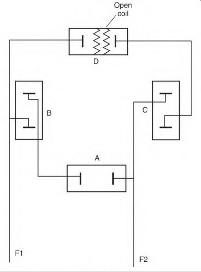
FIGURE 2.9 Two-circuit shunt field with coil D open.
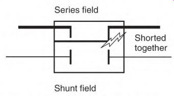
FIGURE 2.10 Shunt field shorted to the series field.
Shunt Field Shorted to the Series Field Symptoms The following are shunt field shorted to the series field symptoms:
• High shunt field amperes
• Some hot coils
• Erratic speed Field Test with an Ohmmeter for the Shunt Field Shorted to the Series Field
Make sure the power is disconnected and that the shunt field leads F1 and F2 are not connected to any other circuit. If there is no short, a test from F1 to S1 will read infinity.
In smaller machines, the series coil is wound on top of the shunt coil, with insulation separating them. Overloading is a common cause of insulation breakdown between the two fields (Fig. 2.10). An overload overheats the series field, deteriorating and eventually charring the separating insulation. This problem requires rewinding all the field coils.
If the machine hasn't been overheated and the reading is 50 megohms or less, cleaning and drying should make an improvement.
Field Testing the Series Field
For this testing, the series field leads (S1 and S2) are connected in series with the armature and interpoles.
Problems in the series field include
• Ground to frame
• Shorted turns
• Open
• Series field shorted to the shunt field (also covered under shunt field problems)
Ground to the Frame Symptoms
The following are the symptoms of a ground to the frame:
• No symptoms (unless more than one coil is grounded)
• Touching the machine gives a shock
• High amperes in armature
• Loss of power
• Arcing at some brushes
• Frequent ball bearing failure
Field Test Using an Ohmmeter to Test for Ground in Series Field
The series field coil is usually wound on top of the shunt field coil. In some machines, it's a separate coil.
Be sure the power is disconnected. Disconnect the series field leads S1 and S2.
Secure one ohmmeter probe to the machine's frame, making good electrical contact. Then, touch S1 with the other probe. No problem would read near infinity. A reading (nearly the same as touching the probes together) indicates a serious ground.
If the coils are loose on the pole iron, a faulty coil may not make continuous contact to the frame. Move all the coils while the test probes are in place. (Field coils should be tightly secured on the pole iron and have no movement.) Loose coils eventually wear through the insulation, causing electrical contact to the pole iron. If there is a low reading of 50 megohms or less, cleaning and drying should make an improvement.
Shorted Turns in Series Field Symptoms
The following Symptoms indicate shorted turns in the series field:
• Loss of power output
• Arcing at some or all brushes
• Output not responding to load changes
Field Test for Shorted Turns in Series Field
The series field is a high-ampere circuit (with large wire). The location of an open, a ground, or shorted turns is usually ve^ obvious. When a fault occurs, there is major arcing, melted wire, and scorched insulation in the fault area, as seen in Fig. 2.11.
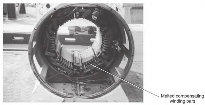
FIGURE 2.11 This short in the series field also melted the compensating winding.
P&H Mine Pro Services.
A shunt field with the same faults will not cause as much damage. Its small wire will melt and open its circuit, with fewer amperes and less arcing.
Operate the machine loaded (with the series field) and check for symptoms described above. Next, operate the machine without the series field. It will now operate as a shunt-wound machine.
If the machine is a motor, the RPM will drop some when the load is applied. If it's a generator, the voltage will drop some as the load is applied. Brush arcing will be normal.
If the machine's series field is multicircuit, there will be a large magnetic imbalance. Some (not all) brushes will arc excessively. Arcing will increase as the load increases.
Shorted turns in the series field are hard to locate without opening the machine. The voltage drop test across each coil is the surest way to detect this problem. This requires accessing the connections between coils.
Open Series Field Symptoms
The following symptoms indicate an open series field:
• One-circuit series field
• Motor: Will not run.
• Generator: No voltage across A1 and S1. There will be full voltage across A1 and A2.
• Multicircuit series field
• Motor: Runs normally with no load, but RPM drops and some brushes arc excessively when loaded.
• Generator: Full-voltage output with no load but voltage drops and some brushes arc excessively when loaded.
Field Test for Open Series Field by Operating Without the Series Field
Disconnect S1 and S2. Operate the machine as a shunt motor or generator.
It should operate as a shunt machine, without the stabilizing effect of the series field.
A motor will slow down as the load is added. A generator's voltage output will drop as the load is added.
Field Test with an Ohmmeter for Open Series Field
Be sure the power is disconnected and that series field leads S1 and S2 aren't connected to any other circuit. A one-circuit series field will read infinity across S1 and S2.
A multicircuit series field requires disassembling the machine and opening the connections. This is described later in the section under "Locating an Open Circuit in Series Field."
Series Field Shorted to the Shunt Field
A test between F1 and S1 with an ohmmeter should read infinity. A reading as high as 1 megohm indicates a potentially serious problem.
The series field is wound on top of the shunt field with a layer of insulation between. This insulation must withstand the pressure of winding large series coil wire tightly around the shunt coil. It also must withstand the thermal growth stress caused by heating and cooling of the series coil. An insulation breakdown usually blows the shunt field open, and makes a very visible burned spot on the coil.
The voltage difference between the two circuits can be the value of the applied voltage.
Locating Problems in the DC Machine
The following tests locate the problem and recommend the extent of repair to be done. Most of the procedures require dismantling the machine to access the components.
All test information should be recorded for future reference.
Locating Problems in the Armature
Ohmmeter Test for Ground in the Armature Circuit
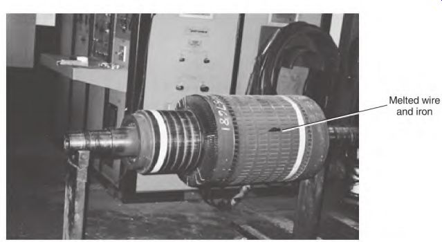
FIGURE 2.12 Armature with its winding melted and fused to the iron.
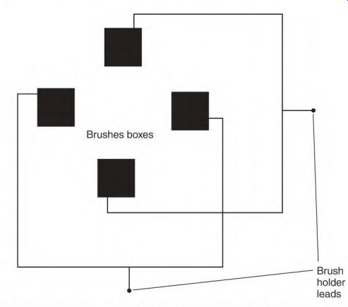
FIGURE 2.13 Every other brush holder is the same polarity; adjacent brush
holders are the opposite polarity. The brush holder (with the brushes removed)
should be isolated from all circuits and from the machine's frame.
The leads A1 and A2 include the brush holder and the interpoles. Test for a ground from A1 to the frame with an ohmmeter. If the reading is low (from 1 to 50 megohms), cleaning and drying may be all that is needed.
It's normal for the armature to have a low megohm reading to the shaft (1 to 50 megohms). Brush dust, which is highly conductive, accumulates behind the commutator during normal operation. This is why DC power is not grounded.
If a ground develops in a machine (for example, a locomotive), all motors on the machine have a common connection to each other. The first indication of a ground is bearing failure. (Leakage current from the commutator travels through the bearings.) Use the following procedure to locate the problem: Lift the brushes and check from the commutator to the shaft with the ohmmeter. A solid ground in the armature (as seen in Fig. 2.12) would require rewinding. If no problem is found in the armature, test the brush boxes-both polarities or adjacent brush boxes-to the frame (Fig. 2.13). If the brush box connected to the interpoles has a low reading, disconnect the interpoles and test again. If a low reading is in the interpoles, cleaning and drying them should improve the reading. A solid ground requires replacing or re-insulating the coil(s). If the brush holder has a low reading, clean and/or replace its bushings and insulators.
Heat-Damaged Interpoles
Interpoles, like the series field, are in series with the armature. If the armature has been overloaded or shorted, high amperes have very likely overheated the interpole coils. If the coils are discolored, they should be replaced or reinsulated.
Locating a Grounded Interpole with AC and a Clamp-on Ammeter
For safety reasons, a low-voltage transformer (with high-ampere capacity) and a current-limiting resistor should be used. This will isolate the DC machine from the equipment ground circuit of the AC power source. The transformer should have enough power to provide a readable number of amperes. A solder gun is sometimes used but can overheat.
Fasten one line of the voltage source to the frame and the other to an interpole lead. Apply a small number of amperes to the circuit. With a clamp-on ammeter, check the amperes at each coil-to-coil connection. The connection that shows no reading (Fig. 2.14) will be beyond the faulty coil.
Disconnect this coil, and check for a ground between it and the previously tested coils. If the end coil contains the ground, feed the circuit from the brush holder connection, and proceed toward A1.
The decision to repair or rewind a single interpole will depend on the age and condition of the machine.
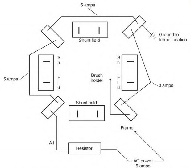
FIGURE 2.14 Locating a ground in the interpole circuit with a clamp-on AC
ammeter and limited AC current.
If any series circuit components show signs of heat damage from high current, all coils in the circuit should be rewound or reinsulated.
Locating a Shorted Interpole Using the AC Voltage Drop Test
A 120-volt AC voltage source with a current-limiting resistor and a voltmeter can be used for this voltage drop test. Limit the amperes to the armature nameplate rating or less. AC works better because of inductance, which is explained in Section 3.
The armature should not be included in the AC test circuit.
At least two interpole coils in series are needed for this test method. The coils are compared, as illustrated in Fig. 2.15. Take a voltage drop test across each coil. (A lower voltage is found across a shorted coil.)
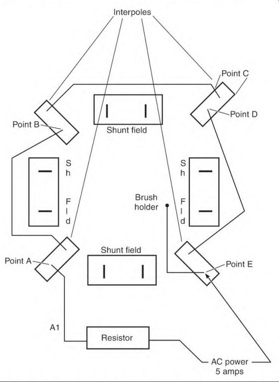
FIGURE 2.15 Locating a shorted interpole with a voltmeter and limited AC current.
This voltage drop test could result in the following "smoke test" if enough amperes are used.
Locating a Shorted Interpole Using the Smoke Test
A shorted turn or two can be very hard to detect when large wire is used in the interpole coils.
The smoke test can be used to locate shorted turns. Use 120 volts AC for the test. Limit the amperes to the armature circuit's nameplate value with a resistor. (Make sure the armature isn't included in the test circuit.) A high circulating current will be transformed into the turns within a short, causing them to smoke almost instantly. Testing should be stopped before the rest of the coils overheat.
If the coils are constructed of flat wire, they can be reinsulated (if they aren't melted or fused together).
Locating Problems in the Shunt Field
The following troubleshooting strategy is applicable to both the shunt machine and the shunt winding of a compound machine.
The Comparison Test
The best method for testing the shunt field (F1 and F2) is to compare one coil's test data to another coil's test data. There's little chance that all the coils would have the same number of turns shorted.
Exception: If all the coils give the same test results and the amperes are too high or too low, the winding data may have been redesigned to operate on a different voltage. This is sometimes done when the shunt field is separately excited.
Needle Probes
If the test instruments are a standard ohmmeter or a voltmeter, a sharp needle probe may be used to puncture the insulation covering a coil-to-coil connection (Fig. 2.16). Neither instrument will cause a high enough ampere flow to damage the small probes. If no problem is found, the puncture can be varnished or wrapped with tape.
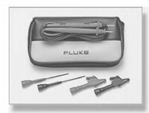
FIGURE 2.16 Needle probes for piercing insulation using a voltmeter or an
ohmmeter. Coils and circuits can be tested quickly without removing the insulation.
Fluke.
Variations in the Shunt Field Circuitry
It's important to understand the shunt field's internal connection before testing it;
• All coils being tested must be alike.
• There may be more than one circuit in the shunt field.
• Some machines have more than one shunt field coil per pole.
Drawing Simple Schematics of a Shunt Field
Figure 2.17a is a DC shunt machine and Fig. 2.17b is a simplified drawing of this machine's connection. (It's a one-circuit shunt field.) The arrows in Fig. 2.17b show where the test probes should contact the connections.
Drawing a Diagram of a Two-Circuit Shunt Field
Figure 2.18a is an example of a two-circuit shunt machine. Figure 2.18b is a simplified drawing of this machine's connection. (It is a two-circuit shunt field.) Each circuit has two coils in series.
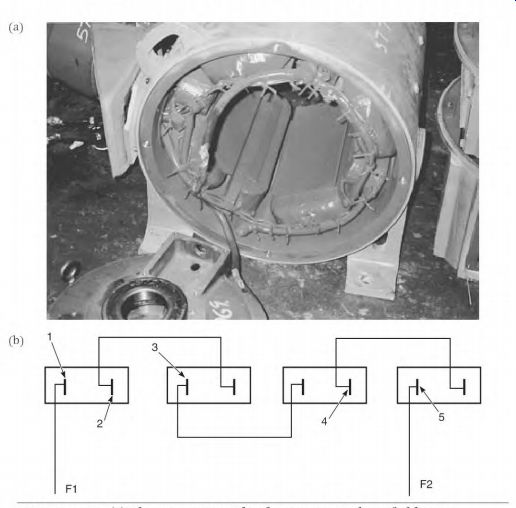
FIGURE 2.17 (a) The connection side of a one-circuit shunt field stator.
(b) Sketch of the shunt field connections in (a).
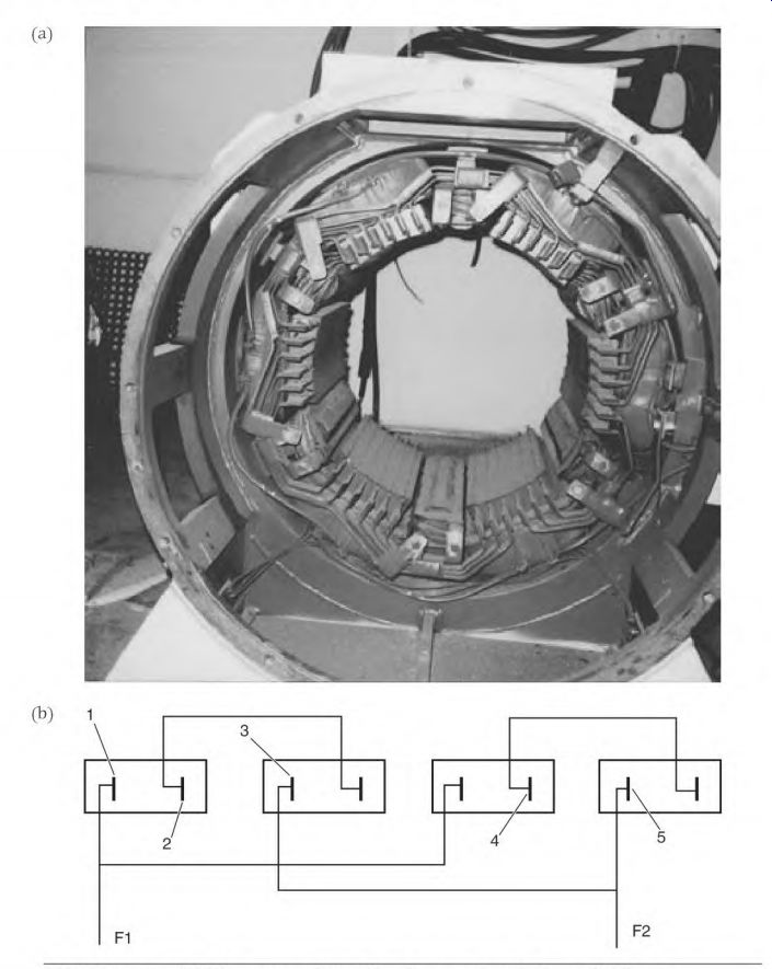
FIGURE 2.18 (a) The connection side of a two-circuit shunt field stator. (b)
Sketch of the shunt field connections in (a).
Drawing a Diagram of a Two-Circuit, Two-Coils-per-Pole Shunt Field
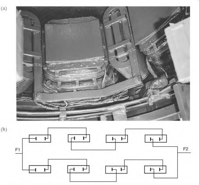
FIGURE 2.19 (a) The connection side of a two-circuit shunt field stator. P&H
MinePro Services, (b) Sketch of the shunt field connections in (a).
Figure 2.19a is an example of a two-circuit, two-coils-per-pole shunt machine.
Figure 2.19b is a simplified drawing of this machine's connection. Each circuit has four coils in series. Problems in the shunt field are
Ground to the frame
Shorted turns
Open circuit and shunt field
Shorted to the series field
Ground to the Frame Symptom
Frequent ball bearing failure.
Ground to Frame Symptoms When More Than One Coil Is Shorted to the Frame
• Higher than nameplate amperes in the shunt field
• Some shunt field coils get hotter than others
• Arcing at some brushes
• A motor will lose power and overspeed (with no load)
• A generator won't develop full voltage and power output
Locating a Grounded Shunt Field Coil Using an Ohmmeter
Separate F1 and F2 from the other leads. Check the resistance of the shunt field with an ohmmeter. A value 25 percent less than the shunt field-rated resistance indicates more than one coil is grounded-or there are shorted turns.
Secure one probe of the ohmmeter to the frame of the motor, making good electrical contact. Touch F1 with the other probe.
No problem will read near infinity. A reading less than the shunt field's total resistance indicates a grounded coil. A very low reading means the ground is close to the lead being touched. A reading close to the resistance of the shunt field indicates the ground is near the other lead.
Remove the insulation from the coil-to-coil connections, and test each coil to the frame. The coil with the least resistance to the frame will contain the ground. Disconnect this coil and verify that it contains the ground. Test the rest of the shunt field coils for a ground.
When two coils short to the frame, at least one coil will be bypassed. The result is high amperes, and all but the bypassed coils will get hot.
The coils should be tight on the pole iron. If not, move them with the ohmmeter attached to the frame and F1.
Shunt field coils are wrapped with insulation and are very well insulated from the frame. Brush dust cannot penetrate this insulation. If the lead-to- frame reading is less than 50 megohms, the coils are probably damp and should be cleaned, heated, and dried out.
If there is dampness, check the coil in the lowest location. Disconnect the bottom coil to determine if that is causing the low reading. If cleaning and drying do not produce a near-infinity reading, replace the coil. (A single grounded coil is one of the few cases in which replacing only one coil is recommended.) DC machines should not have an equipment ground. The bare copper bars of the commutator (combined with highly conductive brush dust) make a high-leakage circuit. If a shunt field coil has a ground, the leakage current will go through the bearings to the commutator, resulting in frequent bearing failure and commutator damage.
Shorted Turns in the Shunt Field Symptoms
The following symptoms indicate shorted turns in the shunt field:
• High amperes
• Shunt field coils hot
• Some or all brushes arc excessively
• A motor will have low starting torque and higher than normal no-load speed
• A generator will not develop full voltage and power when loaded
Locating a Shorted Shunt Field Coil Using an Ohmmeter
Be sure the power is disconnected and that one of the shunt field leads (F1 or F2) isn't connected to the armature circuit. Record the ohmmeter reading across each coil. (There should be a difference of no more than +2 percent.)
Locating a Shorted Shunt Field Coil Using a Voltmeter
Apply nameplate-rated DC voltage to the shunt field (F1 and F2). If necessary, use a resistor to limit the amperes (to no more than 10 percent higher than shunt field nameplate amperes).
Divide the nameplate shunt field voltage by the number of coils in series to find the normal voltage across each coil. If all the coils are good, the voltage across each coil will be within 5 percent of each other.
A shorted coil will have lower voltage across it than the rest of the coils.
When the shunt field's rated voltage is applied, the difference between a shorted coil voltage and normal coil voltage is split among the rest of the coils. The voltage across each coil is increased (which raises the amperes and increases the heat).
Verifying That a Shunt Field Coil Is Shorted Using the Smoke Test
A coil that has a 4 or 5 percent lower ohmmeter reading than the rest may or may not have shorted turns. The smoke test will determine whether there are any. (This test won't damage a coil that isn't shorted.) Open the coil's connections and apply AC voltage to them. The voltage should be limited to the shunt field's nameplate voltage. (Turns within the short will get hot, indicating the coil needs to be replaced.) If the machine has run (with high amperes and temperature) long enough to damage the coil insulation, all coils in the circuit should be replaced.
Locating a Shorted Coil in a Parallel Circuit Shunt Field with an Ohmmeter
Figure 2.20 shows this motor's connection. Two shunt field circuits in parallel should have identical amperes. A circuit with higher amperes than the others will have a shorted coil(s).
When testing from a to b in Fig. 2.20, the ohmmeter will show less resistance than this coil has. (This is because of the loop circuit through the remaining coils in the parallel circuit.) Although the loop circuit's resistance isn't the resistance of the coil, this value can be compared with all coils in the two circuits. If there are no shorted coils, their values will be within 2 percent of each other.
Locating a Shorted Coil in a Parallel Circuit Using a Voltmeter
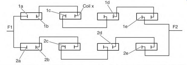
FIGURE 2.20 A drawing of a two-circuit shunt field, with the points for testing
indicated.
If a voltage drop test is used on the machine in Fig. 2.20, each coil should read within 5 percent of the others. Voltage across each coil in this example should be approximately one-fourth the applied voltage. If coil x has shorted turns, the voltage across the rest of the coils in this circuit will be higher than one-fourth the applied voltage. (All coils in this circuit should be replaced.) The following are open shunt field symptoms:
• Very little starting torque
• Overspeeding
• Brushes arc excessively
• High amperes in armature circuit at any speed
Shunt Field with an Open Circuit
The motor won't start a load if the shunt field circuit is open. If it's running when the open occurs, the control should shut it off immediately.
A loaded motor will try to overspeed. It will lose most of its counter- voltage, and the amperes through the armature will become excessively high.
If there is no load, the motor will accelerate until the armature is destroyed.
When test running an unloaded motor with a shunt field, be sure F1 and F2 are securely connected.
Locating an Open Circuit Using an Ohmmeter
The motor in this test has a one-circuit shunt field (Fig. 2.21). There is no ohmmeter reading between F1 and F2. Connect one ohmmeter lead securely to Fl. Pierce the insulation as shown in Fig. 2.21 at point #5. (This is on the coil side of the connection from lead F2.) If there is no reading, proceed to point 4, etc., until a reading is found.
If the open coil was shorted before it opened, all coils in the circuit have probably overheated. In this case, they should all be replaced.
The only exceptions to replacing all the coils are an open coil that has worn through the insulation (from being loose on the iron) or a coil that has been physically damaged.
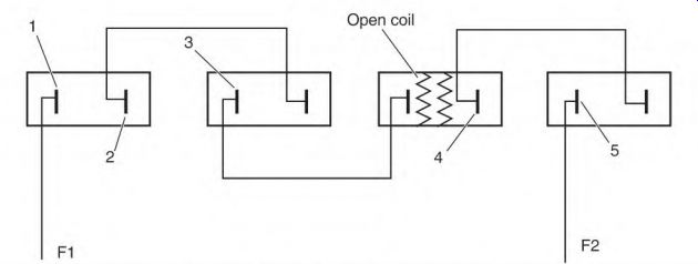
FIGURE 2.21 A one-circuit shunt field with an open coil.
Locating an Open in a Parallel Circuit Using an Ohmmeter
Figure 2.22 shows a two-circuit shunt field. With the nameplate information for the shunt field being 100 volts and 10 amperes, use the following procedure to determine the resistance of a shunt field coil:
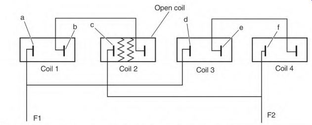
FIGURE 2.22 A two-circuit shunt field with an open coil.
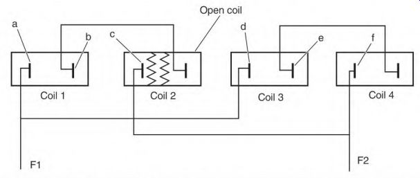
FIGURE 2.23 Test points for locating an open circuit in a two-circuit shunt
field, using an ohmmeter.
100 volts -r 10 amperes =10 ohms (the resistance of the shunt field)
10 ohms x 2 circuits = 20 ohms per circuit
There are two coils per circuit:
20 ohms -r 2 coils = 10 ohms per coil
A test from F1 to F2 would show 20 ohms. This is twice the shunt field's normal resistance.
First, the connections should be checked carefully. A faulty connection will get hot, become charred, and eventually open completely.
In Fig. 2.23 points a, b, c, d, e, and f are internal connections between coils and leads.
If coil 2 is open, a test from a to b will show the resistance of coil 1 only (10 ohms). The same value would be found from d to e and from e to f.
Across open coil 2, b to c, the circuit would be through coils 1, 3, and 4.
The result would be the resistance of three coils added together, or 30 ohms.
A high resistance reading would identify the open coil in a parallel connected shunt field.
Locating an Open in a Parallel Circuit Using a Voltmeter
The shunt field in Fig. 2.24 is rated 100 volts and 10 amps. Coil 2 is open.
If 100 volts are applied to F1 and F2, it will draw 5 amperes, one-half the nameplate rating. Piercing the connections at point a and b with the voltmeter probes will show no voltage. Points d to e and e to f will read 50 volts, or one-half the applied voltage. Point b to point c will read full voltage, identifying the open coil.
Shunt Field Shorted to the Series Field Symptoms
The following symptoms indicate a shunt field shorted to the series field:
• High shunt field amperes
• Some hot shunt field coils
• Erratic speed
Locating Shunt Field Shorted to the Series Field Using an Ohmmeter
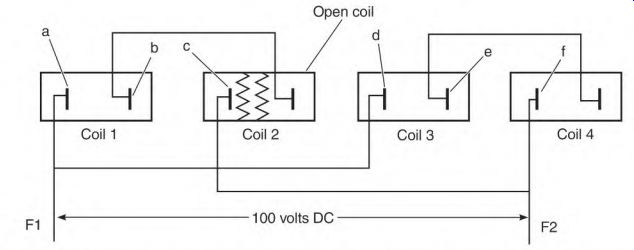
FIGURE 2.24 Locating an open circuit in a two-circuit shunt field with a voltmeter,
and the field's rated voltage.
Normally there are separate leads for accessing the armature and series field.
When a machine is custom made for a definite load, the two circuits may have an internal connection that eliminates one of the shunt field leads.
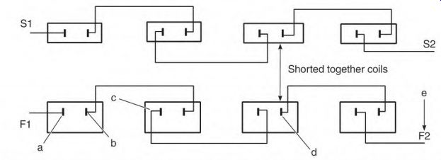
FIGURE 2.25 Locating the short when the series and shunt fields are shorted
together (using an ohmmeter).
Be sure the power is disconnected and disconnect the field leads. If there- is no short, a test from F1 to S1 will read infinity.
Figure 2.25 illustrates a coil-to-coil short in coil 3. Connect one ohmmeter probe to S1. With the other probe, pierce the shunt field connections at points a, b, c, d, and e. Points c and d will have the lowest readings, indicating the short is located in the coil between them.
A shunt and series field insulation breakdown is usually caused by burned insulation between the fields. The load amperes flow through the series field. An overload overheats the series field, deteriorating (and eventually destroying) the separating insulation. This problem requires rewinding all field coils.
Locating Problems in the Series Field
If the brushes arc excessively and a faulty coil in the series field is suspected, run the machine without the series field. It will then operate as a shunt machine. (In a motor, RPM will drop with load increase; with a generator, voltage output will drop with load increase.) If brush arcing is normal, the series field has a problem.
The series field (S1 and S2) is a low-resistance circuit, with very few turns. Anywhere from 5 to 50 turns of large wire are common. The counter- voltage in the armature controls the amperes through this circuit in a motor.
The following problems occur in the series field:
• Ground to frame
• Shorted turns
• Open circuit
• Short to the shunt field (covered earlier in the section under "Field Testing the Shunt Field")
Ground to Frame Symptoms
• No symptoms
• Electrical shock
• Frequent ball bearing failure
If more than one coil is shorted to ground, the symptoms will be arcing at some or all brushes, and some series field coils will get hotter than others.
A motor will have:
• Loss of power
• Lower RPM (loaded)
• Armature amperes higher than nameplate
• Premature bearing failure
In a generator, the following will occur:
• Low voltage/power output
• Premature bearing failure
Locating a Ground in the Series Field with a Clamp-On Ammeter and Limited AC
The AC voltage must be limited to 5 volts or under. A transformer and a (current-limiting) resistor should be used. The transformer should have enough power to provide a readable number of amperes.
Connect one transformer lead to the frame and the other to S1 (Fig. 2.26). Put the ammeter clamp around the coil-to-coil connections, starting at the nearest coil to S2. Check each connection until amperes show on the meter.
Disconnect the faulty coil and check the remaining coils.
Locating a Ground in the Series Field with an Ohmmeter
Disconnect S1 and S2. Secure one probe of the ohmmeter to the frame of the machine, making good electrical contact. Fasten S1 to the other probe.
If there is a low reading, open the coil-to-coil connections, starting at the nearest coil to S2 (Fig. 2.27). When the reading goes to infinity, the ground is located in the last coil disconnected.
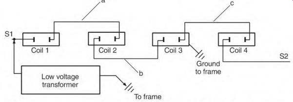
FIGURE 2.26 Locating a ground in the series field with low-voltage AC and
a clamp-on ammeter.
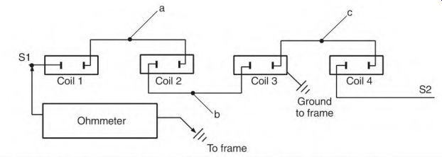
FIGURE 2.27 Locating a ground by opening coil-to-coil connections.
When two coils short to the frame, the turns (or coils) between them are bypassed. Bypassed turns or coils cause a severely unbalanced magnetic field.
This causes some or all of the brushes to arc when the machine is loaded. If the coils aren't tight on the pole iron, move all of them, with the ohmmeter attached to the frame and a lead. If the lead-to-frame reading is less than 50 megohms, the fields should be cleaned and/or heated and dried out.
Shorted Turns in the Series Field Symptoms
If the turns are shorted in the series field, the following can occur:
• Some or all brushes arc when the machine is loaded
• Loss of power
• Machine doesn't react as it should to load changes
Locating Shorted Turns in the Series Field Using AC and the Shunt Field
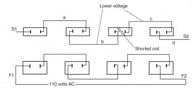
FIGURE 2.28 Locating shorted turns in the series field using the shunt field
as a transformer.
Apply 110 volts AC to F1 and F2 (Fig. 2.28). Pierce series field coil-to-coil connections, and read the voltage across each coil. A lower reading will be found across a shorted coil. A circulating current in the shorted turns of the series coil may raise the amperes in the shunt field. Don't allow the shunt field to overheat.
Locating Shorted Turns Using the Voltage Drop Test and AC
An ohmmeter will not detect any difference between coils when only a few turns are shorted out (because of the circuit's low resistance). A micro-ohmmeter will work; the voltage drop test (using 2 to 5 volts AC) also will work (Fig. 2.29).
Never apply more than 2 to 5 volts AC to the series field (S1 and S2). A destructively high voltage will be transformed into the shunt field.
Remove the insulation from the series field coil-to-coil connections.
Apply 2 to 5 volts AC to S1 and S2. Read the voltage across each series field coil. A lower reading will be found across the shorted coil.
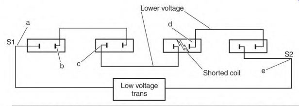
FIGURE 2.29 Locating a shorted coil in the series field using low-voltage
AC and the voltage drop test.
Locating an Open Circuit in Series Field
A one-circuit series field with an open circuit will have the following symptoms:
• A motor won't start. The only complete circuit will be the shunt field.
• A generator won't have a voltage output. A1 and A2 will read full voltage.
A two-circuit series field with an open circuit will have these symptoms:
• A motor will lose power, and some or all of the brushes will arc excessively (from magnetic unbalance).
• A generator will have full voltage output (at no load). As it is loaded, the voltage output will drop some, and some or all brushes will arc excessively.
Locating an Open in a One-Circuit Series Field Using an Ohmmeter
An ohmmeter connected to S1 and S2 will read infinity (Fig. 2.30). Starting with an ohmmeter probe connected to S1, pierce each coil connection from S1 to S2 until there is no reading. The reading across the faulty coil will be infinity.
Locating an Open in a Two-Circuit Series Field Using a Voltmeter
Remove the insulation from the series field coil-to-coil connections. Use a resistor that limits the amperes to the armature's nameplate value, and apply DC voltage to S1 and S2 (Fig. 2.31).

FIGURE 2.30 Locating an open coil in a single-circuit shunt field with an
ohmmeter.

FIGURE 2.31 Locating an open coil in a two-circuit series field using limited
current DC and a volt-meter.
Never apply the motor's rated voltage to S1 and S2.
Check across each coil with a voltmeter. Full voltage will be found across the open coil. Coils a and b will show half voltage. Coil c will read full voltage and coil d will read zero voltage.
Identifying Leads of a Compound DC Motor with an Ohmmeter
Most compound DC motors have three circuits, the armature (A1 and A2), the series field (S1 and S2), and the shunt field (F1 and F2). Use an ohmmeter to locate the three pairs (that have a circuit to each other). The shunt field leads (F1 and F2) are usually smaller than the armature and series field leads. The shunt field has much higher resistance than the armature and series field.
Identify and temporarily label the shunt field leads F1 and F2. Identify the armature leads by touching one ohmmeter probe to a lead and the other to the commutator. Label them A1 and A2. Temporarily label the remaining leads S1 and S2.
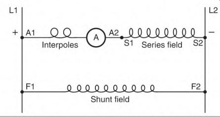
FIGURE 2.32 Identifying unmarked leads to conform to NEMA standards.
Connect the motor as shown in Fig. 2.32 and apply enough DC power to make it rotate. The rotation should he counterclockwise facing the commutator. Interchange A1 and A2 if the rotation is wrong.
Disconnect F1 and apply enough power to A1 and S2 to get rotation. If rotation reverses, interchange and re-label the series field leads.
NEMA standard rotation is counterclockwise facing the commutator end, with positive on A1 and F1.
Section 2 Review
1. Most of a DC machine's problems occur in the armature (57). T F
2. Lacquer thinner is a good liquid for cleaning a commutator (58). T F
3. An open armature coil may cause dead spots (58). T F
4. Burned commutator segments spaced equal to the distance of two like-polarity brushes indicate an open equalizer (58). T F
5. Brushes are all interchangeable if they fit the brush holder (59). T F
6. Name two types of current flowing in a brush's conduction zone (60).
7. Split brushes reduce the circulating current in the conduction zone (61). T F
8. A spiral groove cut in a commutator improves its performance (61). T F
9. All brushes in a multiple brush holder should carry the same number of amperes (62). T F
10. All motors should have their brush boxes the same distance from the commutator (62). T F
11. Uneven distance between brushes can affect commutation (62). T F
12. Spring tension must be the same for all brushes (63). T F
13. High amperes require heavier spring tension (64). T F
14. Brush shunt wire size isn't important because the brush box will carry the current (65). T F
15. How can uneven commutator segments be detected (65)? 16. Name two causes of excessive brush dusting (65).
17. Gray brushes are better than black brushes for (66)
a. high amperes.
b. less wear.
c. low amperes.
18. Give the formula for finding brush current density (66).
19. Silicone grease should be used on DC motors (66-67). T F
20. Why should brushes be properly seated (67)?
21. What will cause a brush face to have a flat black color (67)?
22. The final brush setting for a DC motor is the spot that has less than V2 volt between segments (69). T F
23. Moving the brush holder-one segment at a time against rotation- until there is the least amount of sparking is called the black band adjustment for a motor (69). T F
24. Generators should always have their residual magnetism restored-by applying DC to F1 and F2-after AC has been used to set the brushes on neutral (69). T F
25. Name two ways to test an armature on site (70-71).
26. Name two symptoms of a grounded shunt field (71-72).
27. All coils should be replaced when an ohmmeter reading is between 1 and 50 megohms (72-73). T F
28. A circuit that is being tested for a ground should be isolated from all other circuits (73). T F
29. Why are shorted turns in the series field circuit usually very obvious (76-77)?
30. A compound wound DC motor will run if the series field is not connected (78). T F
31. How is a compound wound generator affected when the series field is not used (78)?
32. The commutator is a high-leakage circuit (79). T F
33. Why are interpoles subject to problems if the armature is overheated (80)?
34. Why should AC and a resistor be used to supply AC for testing (82)?
35. DC will cause high current to flow in shorted turns (83). T F
36. Why is it important to draw a schematic of a complicated circuit before testing it (84)?
37. Name four problems that occur in the shunt field (85).
38. An ohmmeter will show a lower resistance reading when the test is close to a grounded coil (88). T F
39. Why is an equipment ground not recommended for DC machines (88)?
40. A coil with shorted turns will show a reading than the rest of the coils (89).
a. higher resistance
b. lower resistance
41. Dividing the test voltage by the number of coils being tested will give the approximate voltage found across each coil-if none are shorted (89). T F
42. A + or - of difference is allowable when comparison testing coils with an ohmmeter (89).
a. 2%
b. 5%
c. 10% 43. A + or - of difference is allowable when comparison testing coils with a voltmeter (89).
a. 2%
b. 5%
c. 10%
44. What will happen to the armature if the shunt field opens while it's operating with no load (90)?
45. Loose coils can lead to a grounded or open circuit (91). T F
46. An open coil in a two-parallel circuit shunt field will of the shunt field (91-92).
a. lower the resistance
b. raise the resistance
47. An insulation breakdown between the shunt and series fields is usually caused by high amperes in the series field (94). T F
48. Running a compound DC machine without the series field is a quick way of ruling out the series field as the problem (94). T F
49. The resistance of the series field has very little effect on the amperes of its circuit (94). T F
50. A grounded series field coil may not show a problem (95). T F
51. The shunt field should never have AC voltage applied to it, because the series field will be destroyed by the high voltage being transformed into it (97). T F
52. Leads F1 and F2 are usually larger than the rest of the DC machine's leads (99). T F