AMAZON multi-meters discounts AMAZON oscilloscope discounts
The DC machines described in this section are motors or generators. The term machine is used when the test procedure is the same for both. A motor can be converted to a generator (and vice versa), so the terms motor and generator are used only when the explanation applies to one or the other.
DC generators produce very high-quality power, but (because of maintenance and other costs) AC powered DC drives are used for most motor applications.
DC power is used for some high-voltage power transmission. DC current flows through the whole area of a wire, making it more efficient than AC for long distance transmission. High-voltage AC current uses only the outer portion of the wire. Only two transmission lines are needed with DC, and in an emergency, the earth can be used as a second conductor. At the user end, DC is converted to three-phase power and distributed to substations.
DC generators also make the best power for arc welders. They provide steady voltage and a non-fluctuating current that flows in one direction.
The DC motor has excellent speed control with very good torque and horsepower characteristics. Because of its armature design and function, it has very smooth torque from 0 RPM to base speed. The DC motor also has full-rated horsepower above base speed.
Basic Electricity as It Applies to Motors
The properties of electricity are volts, resistance, and amperes. Voltage is the driving force, resistance is the work to be done, and amperes get the work done.
Volts
Voltage (electromotive force, or emf) is the driving force that causes the amperes to flow through the resistance of the load. Even if there is no circuit or path, voltage can he present. The volt can be compared to air or water pressure. When voltage is raised, more amperes will flow through the resistance (load). When voltage is lowered, fewer amperes will flow.
When the voltage is varied, the number of amperes flowing through a given resistance (load) will go up or down with the voltage change.
Another comparison of the volt to air or water pressure is containment.
Higher voltage requires stronger (thicker) insulation.
Resistance controls the number of amperes that flow in a circuit. When a constant value of voltage is applied, as resistance goes up, amperes go down and as resistance goes down, amperes go up. As the resistance value varies, the number of amperes varies the opposite way. All loads have some form of resistance. The resistance of a device is measured in ohms. (Ohm's Law is discussed later in the section.)
Resistance
Resistance is opposition to ampere flow and measured in ohms. It is seldom measured, so is just called resistance. It is common to measure amperes.
Two factors furnish resistance to current flow in an electric motor. First is the resistance of the wire in the coils that form the poles. Each wire size has a resistance value per 1000 feet at a given temperature. Coils of wire used in the shunt field of a DC motor have enough feet of wire to limit the amperes to a safe level (and not overheat). The second factor is the interaction of the winding conductors and the magnetic circuit of the motor. This will be explained under "Counter emf in DC motors in the section "Counter-voltage" and in Section 3 under "Inductive Reactance" in AC motors.
Ampere
The ampere is a measurement of the number of electrons flowing in a wire.
The number of amperes flowing in a circuit is controlled by two factors: the voltage applied and the resistance of the load. The voltage and/or the resistance are varied to control the amperes. The formula called Ohm's Law (described later in the section) calculates the number of volts and/or the amount of resistance needed to predict the number of amperes in a circuit.
Most electrical breakdowns involve ampere flow. When insulation breaks down, heat created by ampere flow destroys it. Excessive amperes flowing in a wire cause a wire to become hot.
The number of amperes flowing through a coil controls the coil's magnetic strength. As the number of amperes changes, the coil's magnetic strength will vary with the change.
The direction of ampere (current) flow determines the polarity of the coil.
Figure 1.1 shows the left-hand rule for determining the polarity- of a DC coil.
The right wire size is a very important part of motor design. The wire size is determined according to its cross-sectional circular mil area. The number of amperes that flow in a motor's circuits and the motor's cooling ability determine the wire size.
The coils used in the shunt field of a large DC motor have much larger wire size (circular mils per amp) than the coils used in single- or three-phase induction motors. This is because the coils have a large mass and do not cool easily. It's common to find 1000 (or more) circular mils per amp in the shunt field coils of a large DC motor. It is also common for single- and three-phase motors to have 300 to 350 circular mils per amp
Table 1.1 shows the wire size converted to circular mils plus other data.
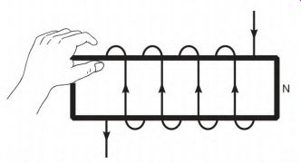
FIGURE 1.1 Left-hand rule. Place the left hand on a coil of wire with the
fingers pointing in the direction of current flow. The thumb points to the
north pole.
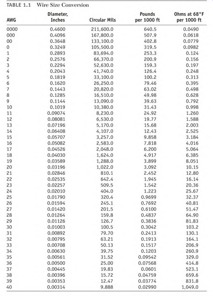
TABLE 1.1 Wire Size Conversion
Additional Information on Copper Wire
This wire table can be remembered very easily if a few simple points are kept in mind:
• A wire three sizes smaller than another wire has half the area of the larger wire. For instance, No. 20 AWG copper wire has half the area of
No. 17 AWG copper wire. Therefore, two No. 20 wires in parallel have the equivalent area of one No. 17 wire.
• A wire three sizes smaller than another wire has twice the resistance of the larger wire.
• A wire three sizes smaller than another wire has half the weight of the larger wire.
• A No. 10 AWG copper wire is approximately 0.10 inch in diameter, has an area of approximately 10,000 circular mils, and has a resistance of 1 ohm per 1000 feet.
If there are too few circular mils per amp, the coils will overheat and the motor's insulation will deteriorate prematurely. Excessive heat increases copper loss and lowers the motor's efficiency. Copper gains resistance as its temperature rises. As copper resistance goes up, the amperes go down, lowering the motor's horsepower output.
Ohm s Law
The relationship of voltage, amperes, and resistance is explained with a formula called Ohm's Law. The following formulas, in which E (electromotive force) = volts, I (intensity of current) = amperes, and R = resistance, predict the results when designing electrical devices: Volts divided by resistance equals amperes (E h- R = /) Volts divided by amperes equals resistance (E + I = K) Amperes multiplied by resistance equals volts (I X R = E) Varying the voltage or the resistance controls amperes.
Watt
The word watt is short for joules per second. A watt is the measurement of power being used to do work. The number of watts is found by using the formula volts X amperes = watts. A power meter (which determines power cost) multiplies volts X amps and measures the time involved. The cost is determined by the kilowatt hour (1000 watts for 1 hour). A motor converts electrical energy directly into mechanical energy. One horsepower (hp) equals 746 watts. One horsepower has the ability to lift 550 pounds 1 foot in 1 second.
Watts and horsepower are directly related to the physical size of motors.
Some motors are rated in kilovolt amperes (kVA) instead of horsepower. All transformers are rated in kVA. The formula (volts X amperes = watts) shows that when the number of watts is constant, as the number of volts goes up, the number of amps goes down. For example, assume 1000 watts are required for a given load. If the power supply were 10 volts, it would take 100 amperes to produce 1000 watts of power. The wire size would have to be large to carry 100 amperes.
With a 100-volt power supply, only 10 amperes are needed to produce 1000 watts. The wire size required would be much smaller. This is the reason large electric motors are designed to operate on high voltage.
Low amperes allow smaller wire to be used. Power lines are a good example of this. On the high-voltage (power line) side of a transformer, the wires are very small compared to those on the low-voltage side (load side).
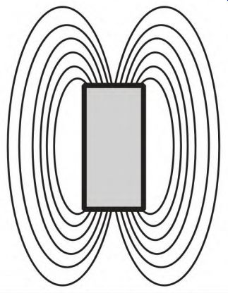
FIGURE 1.2 A bar magnet has lines of force that go from one pole to the other,
through the air.
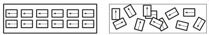
FIGURE 1.3 The magnet is fully magnetized if the molecules of the iron are
aligned.
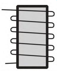
FIGURE 1.4 An electromagnet consists of an iron bar with a coil of wire wound
around it.
Magnets and the Magnetic Circuits
The Bar Magnet
The bar magnet illustrated in Fig. 1.2 shows the invisible lines of force (flux) going out one pole and completing a magnetic circuit to the other pole. Lines of force will go through air, insulation, and nonmagnetic materials.
The bar magnet is at full magnetic strength when its molecules are in alignment, as seen in Fig. 1.3.
The Electromagnet
A piece of iron with a coil of wire wound around it makes a basic electromagnet (Fig. 1.4). Magnetic strength is controlled in an electromagnet by raising and lowering the amperes. Reversing the current flow will reverse its polarity.
The Magnetic Pole
A pole in the stator of a DC machine is a coil of wire wound around a piece of iron (called a pole shoe or pole iron), as shown in Fig. 1.5.
A pole is equal to 180 electrical degrees. One north pole and one south pole equal 360 electrical degrees. There are always pairs of poles.
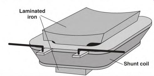
FIGURE 1.5 A field pole consists of laminated or solid iron and a coil of
wire.
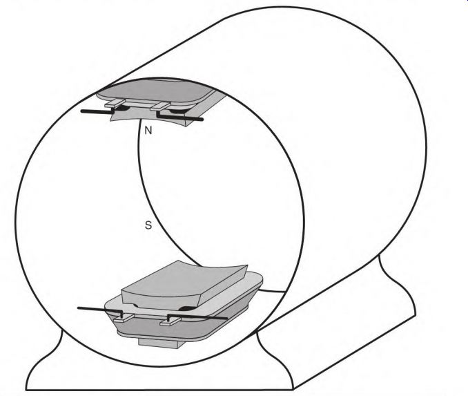
FIGURE 1.6 A two-pole stator.
The bore (through the stator of the machine) is divided very precisely by the number of poles. The electrical degrees are equal to the mechanical degrees in a two-pole motor (as seen in Fig. 1.6). Half of the mechanical circle will contain 360 electrical degrees in a four-pole motor (Fig. 1.7).
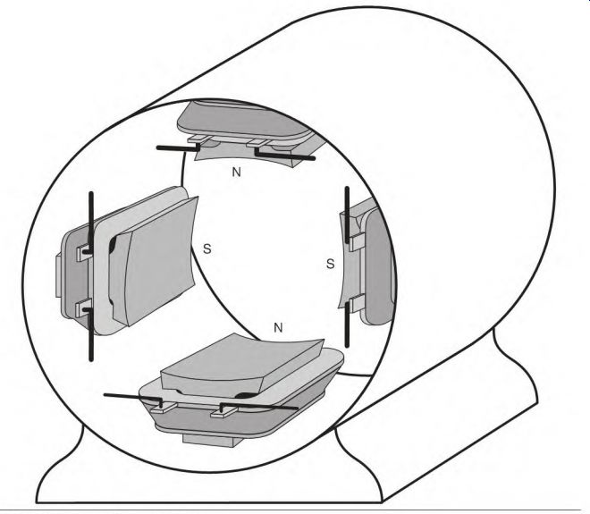
FIGURE 1.7 A four-pole stator.
Ampere Turns
Ampere turns is a term in a formula used in designing a pole. The strength of a pole is governed by the number of turns in its coil and the number of amperes flowing in them.
The shunt field of a DC machine has a large number of turns and a small number of amperes. Fewer turns and more amperes will do the same job but would be much more expensive to operate.
The series field in the DC machine is in a high-ampere circuit. It has very few turns, but its magnetic strength can be comparable to that of the shunt field.
The Magnetic Circuit
The circuitry of an electric motor sometimes seems very complicated. The armature of a DC motor is a good example. When the energized coils of the armature are isolated and displayed (Fig. 1.8), they take the same shape as the electromagnet shown in Fig. 1.4-a coil of wire around a piece of iron.
Magnetic circuits in most motors are a variation of the basic electromagnet in Fig. 1.4.
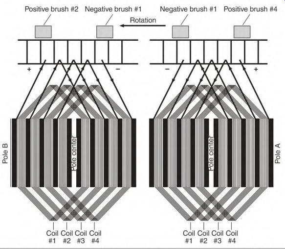
FIGURE 1.8 Poles are formed in an armature circuit from energized coils around
idle coils.
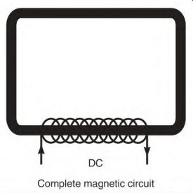
FIGURE 1.9 An energized coil of wire around a loop of iron has a path for
the magnetic flux it creates.
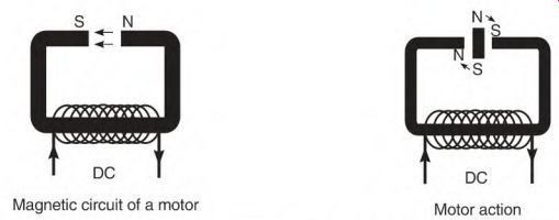
(left) FIGURE 1.10 Poles form in the opening when the iron loop is opened. (right)
FIGURE 1.11 A bar magnet placed in the open space produces torque.
A complete magnetic circuit (using a coil of wire as its power source) is shown in Fig. 1.9. The amount of current through the coil controls the number of lines of force (flux) in the magnetic loop.
When the magnetic loop is opened (Fig. 1.10), north and south poles are established on the ends of the iron. The direction of current flow through the coil determines the polarity at the ends of the iron. In a motor or generator, these poles are stationary and are part of the stator. The outer shell of the stator carries the lines of force from pole to pole.
If a bar magnet is placed in the opening (Fig. 1.11), the magnetic forces will cause torque. The bar magnet will try to align with the poles of the stator as shown in Fig. 1.12. (Unlike poles attract, and like poles repel.)
Figure 1.13 shows the basic magnetic action of all electric motors. The poles of the bar magnet represent the magnetism developed in the armature of a motor.
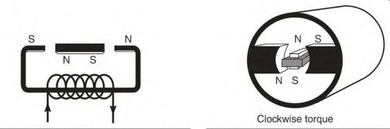
FIGURE 1.12 When the bar magnet is aligned, there is no torque, and it becomes
part of the magnetic path.
FIGURE 1.13 Clockwise torque A stator (with an electromagnet in its bore) illustrates basic motor action found in all motors.
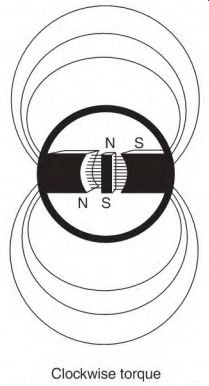
FIGURE 1.14 Oversaturation causes magnetic lines of force to go through the
air (when there isn't room for them in the iron).
Magnetic Saturation
The iron of a magnetic circuit has a limited capacity to carry lines of force. When this capacity is reached, it is called magnetic saturation or fully magnetized. When the iron's capacity is exceeded, it is called oversaturation.
Figure 1.14 illustrates what happens to some of the lines of force when oversaturation occurs.
Magnetic Balance
When electric motors and generators are designed, great care is taken to magnetically balance all the poles. The poles are placed an equal distance from each other around the stator. Each pole has the same number of turns of wire and produces the same amount of magnetism. The shell of the stator is the outer part of the magnetic circuit. The iron of the armature completes the inner part of the magnetic circuit.
Magnetic unbalance will cause bearing problems, loss of power, and internal heating in the armature.
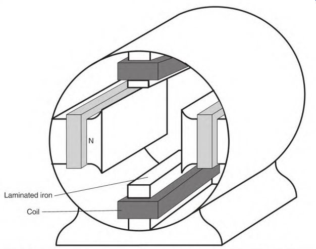
FIGURE 1.15 Interpoles in a two-pole machine-located at 90 electrical degrees-form
the stator poles.
Neutral Position in the Stator
The neutral spot is located an equal distance between the north and south poles. Magnetic neutral is 90 electrical degrees from each adjacent pole center. Interpoles (explained later in the section) are located in the stator's neutral position (Fig. 1.15). The correct brush setting will align the pole centers of the armature with the stator's neutral position on all DC machines.
Circuits of the DC Machine
A DC motor or machine has three basic circuits:
• Armature and interpole leads, A1 and A2
• Series field leads, S1 and S2
• Shunt field leads, F1 and F2
They are designed with various combinations and connections to suit the needs of a given load. A more in-depth explanation of each component will come later in this section.
As previously stated, the DC machine is interchangeable as a motor or a generator, so the word machine is used in this guide when explanations apply to both motor and generator.
• The armature generates all the power as a generator. It creates all the torque as a motor. The armature and interpoles are a series circuit. The purpose of the interpoles is to improve brush commutation. They are connected either between A1 and the armature or between the armature and A2.
• The series field is connected in series with the armature and interpoles.
Its purpose is to stabilize the output of the machine as the load changes.
• The shunt field provides magnetism for the armature. Lines of force or flux (produced by the shunt field) create power (VA) in the armature as a generator and create torque as a motor.
Rules for Generating Direct Current
When a conductor cuts or is cut by magnetic lines of force, a voltage is generated in it. The amount of voltage can be controlled by:
• The number of conductors in the armature
• The number of magnetic lines of force (or flux) from the stator
• The speed at which the armature conductors cut or are cut by the lines of force
The number of conductors is the same as the number of turns in the slot of an armature. Each turn of wire cuts lines of force and generates a given amount of voltage. The voltage generated in each turn is added to the next turn-this compares to flashlight batteries in series. The number of turns in the slots of the armature determines the basic voltage output of a generator.
The number of magnetic lines of force (being cut by the armature's conductors) controls its voltage output value. As the number of lines of force increases, the voltage value also increases in the conductors. The number of lines of force can be varied with a control that changes the number of amperes flowing in the stator fields. The output voltage will vary with the change in ampere flow through the stator fields. This control adjustment won't make a large change in the voltage output of a generator.
The speed at which the conductors cut the lines of force is determined by the generator's RPM. The recommended speed is on the generator's nameplate. The voltage output value will change with the speed change.
The Shunt Generator
The shunt generator has two circuits (Fig. 1.16), the armature and interpoles (A1 and A2) and the shunt field (F1 and F2).
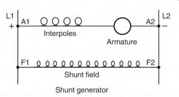
FIGURE 1.16 This schematic identifies the two circuits found in a shunt generator.
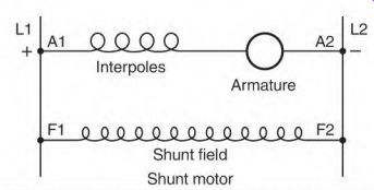
FIGURE 1.17 NEMA standard shoving polarity and the lead number combinations
for a shunt motor.
Figure 1.17 shows the NEMA (National Electrical Manufacturers Association) standard connection for counterclockwise rotation facing the end opposite the shaft.
The Armature and Interpoles
Armature leads are identified as A1 and A2. The armature windings produce all of the generator's power output. The number of turns of wire in the slots of the armature determines its voltage output value. The ampere rating of the generator determines the armature winding's wire size.
The armature circuitry consists of many coils that are connected to the commutator segments. The commutator segments control the direction of current flow in each coil of the armature. The basics of this circuitry and a more detailed explanation are provided in the section, "Operation of a DC Motor." Interpoles are poles strategically placed in the stator to decrease brush arcing. They will be covered in depth later in this section.
The Shunt Field
The shunt field (Fig. 1.18) consists of coils of wire and laminated iron. Each coil and its iron make a pole. Fig. 1.19 shows a four-pole sketch. The coils are connected so that each is the opposite polarity from the one next to it. The number of north poles always equals the number of south poles. Figure 1.20 shows a four-pole stator.
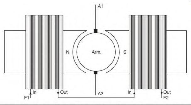
FIGURE 1.18 This sketch shows how pole-to-pole connections are made in a two-pole
machine.
The purpose of a generator's shunt field is to furnish magnetic lines of force (flux) for the armature conductors to cut. Power is produced as armature conductors cut the lines of force. The shunt field coils consist of hundreds of feet of wire. The total length of the wire in these coils controls the current. (Each wire size has a resistance value per 1000 feet.) The large quantity of wire in the shunt field circuit keeps its coils from overheating.
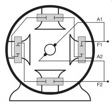
FIGURE 1.19 This sketch shows how pole-to-pole connections are made in a four-pole
machine.
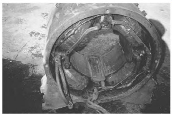
FIGURE 1.20 A four-pole shunt wound stator. P6-H MinePro Services.
Operation of the Self-Excited Shunt Generator
The iron of the stator poles is still magnetized from its previous use. This is called residual magnetism. A few lines of force between poles are created by:
The resistance of the control lowers the number of shunt field amperes--which lowers the number of lines of force (flux) cut by the armature conductors, resulting in a lower voltage.
The shunt field can be excited separately with another power source.
Separate excitation reduces the voltage drop common to the self-excited design.
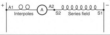
FIGURE 1.23 The schematic of a series generator.
The Series Generator
The series generator has two circuits that are connected in series with each other, the armature and interpoles (A1 and A2) and the series field (S1 and S2). Figure 1.23 shows a standard connection for counterclockwise rotation facing the end opposite the shaft.
All of the amperes produced by the armature pass through the series field. The series field coils are constructed with a few turns of wire that are large enough to carry the full ampere output of the generator. The large wire makes it a very low-resistance circuit compared to the shunt field circuit.
Operation of the Self-Excited Series Generator
The field pole iron has residual magnetism from the previous operation.
The conductors of the armature cut lines of force of the residual magnetism and generate an excitation voltage. The output voltage will remain at the excitation voltage value until a load is applied. The excitation voltage will cause a small amount of current to flow through the load. This current goes through the series field, strengthening its magnetism and creating more lines of force.
When the armature conductors cut more lines of force, they generate higher voltage and amperes until the load demand is stabilized. The voltage output will remain at this value until more load is added. The voltage and ampere output will increase with the load increase until full power output of the generator is reached.
At this time, the amperes in the series field create full magnetic saturation in the pole iron.
The series generator with no load will create only excitation voltage. The load regulates the voltage output. This characteristic limits its use.
The compound generator has three circuits (Fig. 1.24), the armature and interpoles (A1 and A2), the series field (S1 and S2), and the shunt field (F1 and F2).
Figure 1.25 shows the NEMA standard connection for counterclockwise rotation facing the end opposite the shaft.
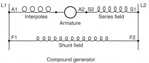
FIGURE 1.24 A compound generator, showing its three circuits.
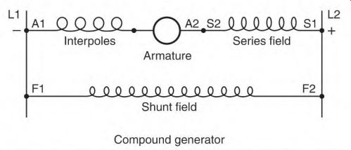
FIGURE 1.25 The NEMA standard connection for a compound generator, showing
polarity and lead numbers.
The Armature and Interpoles
As shown earlier, the armature leads are identified as A1 and A2. The armature windings produce all of the generator's power output. The interpoles ensure good commutation.
The Series Field
The series field (S1 and S2) has coils that either are wound over the shunt field coils or are separately formed coils. If they are wound on top of the shunt field coils, they're separated with insulation. There is no internal connection between the series and shunt field coils. The series field coils can get hot because they are in a high-ampere circuit. They're located on the outside of the shunt coils, where they receive maximum cooling.
When the series field coils are separate, the coils are formed, insulated, and placed on the pole iron between the shunt field coils and the armature (Fig. 1.26).
The Shunt Field
As described earlier, the shunt field leads are identified as F1 and F2. The purpose of a generator's shunt field is to furnish magnetic lines of force (flux) for the armature conductors to cut. As the conductors of the armature cut the lines of force, power is produced.
Operation of the Self-Excited Compound Generator
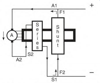
FIGURE 1.26 Current flow created by residual magnetism and the resulting lines
of force.
Residual magnetism that is left in the pole iron from the previous operation creates a few lines of force. The armature conductors cut these lines of force and create an excitation voltage. The excitation voltage will cause a small current to flow in the series and shunt fields (Fig. 1.26). This current increases the magnetic strength of the pole iron, creating more lines of force (which increase the voltage and current until full voltage output is reached). At this time, the pole iron has full magnetic saturation. This procedure can take several seconds. The shunt field furnishes nearly all the magnetism at no load.
As the load is applied, the load current produced by the armature goes through the series field, producing lines of force. These lines of force add to the shunt field's lines of force. Instead of the iron losing magnetism (as with the shunt generator), the series field maintains full magnetic power.
The results are full field strength and no drop in output voltage. The added strength of the series field stabilizes the voltage as the load is increased.
The number of turns of wire in the series field directly affects the amount of stabilizing voltage it produces. The flat-compound generator has enough turns in the series field to raise the voltage as the load is applied. When this generator reaches its full rated load, the voltage is at nameplate value.
The over-compound design will have enough turns in the series field to raise the voltage to a higher value at full load than it had at no load. (The over-compound generator's output can be controlled downward to meet the requirement of the load.)
Compound Generator Control
Figure 1.27 shows a (basic) compound generator control. Its two main parts are a voltage control and a current control. (The control is designed for over- compound generators and controls the voltage downward.) The design of these controls can vary from simple variable-resistor types to electronic ones. The more sophisticated type will react quickly to load changes and produce a very stable power output.
The voltage control varies the amperes of the shunt field. (Decreasing the shunt field amperes reduces the magnetic flux and lowers the output voltage.) This control doesn't make a large change in voltage.
The voltage control components are small compared to those of the current control because they control a small amount of current.
The current control diverts some of the amperes directly to the line, bypassing the series field. (The series field raises the voltage as the load increases.) The voltage increase is controlled by diverting some amperes.
The current control components are large because they control high amperes.
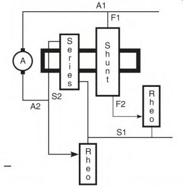
FIGURE 1.27 A compound generator with its control. The shunt field control
is the voltage control, and the series field control is the current control.
The Cumulative Compound Connection (Generator)
The connection for the compound generator described earlier is called cumulative compound. If the series field is connected so that its polarity is the same as that of the shunt field, the connection is called cumulative. This connection adds the magnetic flux (lines of force) of the series field to that of the shunt field as the load increases. This tends to stabilize the voltage output.
The Differential Compound Connection (Generator)
When the series field polarity is opposite that of the shunt field, the connection is called differential. This connection (Fig. 1.28) has an effect that is opposite that of the cumulative connection.
The series field flux (lines of force) will cancel an equal amount of shunt field flux. This results in fewer lines of force for the armature conductors to cut, causing the voltage output of the generator to drop. If the load is decreased, the voltage will increase.
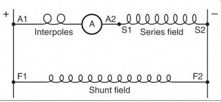
FIGURE 1.28 The differential connection, with the series field bucking the
shunt field.
The differential connection in a generator is used to protect a load that can be damaged by high amperes. An example is a motor that is subject to stalling or regular overloading. The connection is used on large mining- equipment generators and all DC arc-welder generators.
Series Field Connections for a Motor and a Generator
The current flow through the armature of a motor is opposite that of a generator. A motor uses amperes from the line. A generator produces amperes.
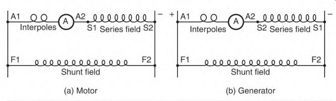
FIGURE 1.29 (a) The NEMA standard for a motor, (b) The NEMA standard for a
generator.
Special-Purpose Machine Connections
Some special-purpose machines have an internal connection that connects the armature-interpole circuit with the series field circuit. They have one armature lead and one series field lead. Reversing these leads reverses the rotation and changes the connection from cumulative to differential.
The DC Arc Welder
The differential connection is used in a DC arc welder (Fig. 1.30). The components of a welder include:
• Exciter generator
• Shunt field
• Armature and interpoles
• Series field
• Reactor
The exciter generator is a separate DC source for the shunt field. (It's normal^ a small generator built into the machine.) It provides power for only the shunt field of the welder. Its power output is very constant and isn't affected by the welding load.
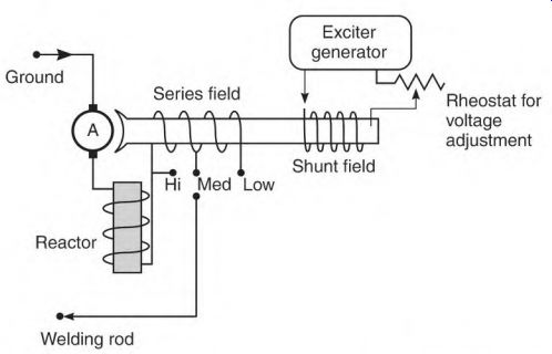
FIGURE 1.30 All DC welder generators have the same basic components, as shown
here.
The series field leads S1 and S2 have to be reversed when a motor is used as a generator, and vice versa. Figure 1.29 shows the NEMA standard connection for both applications. If a motor connection is used on a generator, the ampere flow through the series field makes the connection differential.
The shunt field is located on the same pole iron as the series field. It provides a constant source of magnetic lines of force for the conductors of the armature to cut. There is no electrical connection between the two circuits.
The welding load varies from the extremely high amperes of a short to the high amperes of an arc. It is basically a controlled short. For this reason, it's important to separately excite the shunt field so it's not affected by the demand of the welding load.
The shunt field requires a small number of amperes, so its control components are small. The output voltage of the welder is varied just a small amount with this control.
The armature and interpole conductors must be very large. Because of the low voltage and high ampere output, there are only a few turns of wire in the slots of the armature. (They're made of large flat wire.) Interpole coils are connected in series with the armature. (Their coils are also made of large flat wire.) The interpole coil turns are spaced apart for maximum cooling.
The series field coils have very large conductors. The coil turns are spaced apart for maximum cooling (Fig. 1.31). There are usually three or more taps connected to the series field. These taps select the number of amperes as needed and are the current control …
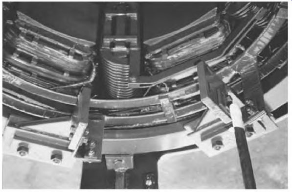
FIGURE 1.31 Coils with the turns separated for maximum cooling.
…. for the welder. The tap that includes all the series field turns will produce a maximum amount of canceling flux and will be the lowest ampere tap.
The rest of the taps will include fewer of the series field turns. The highest ampere tap will include the least amount of series field turns.
The reactor coil consists of very large conductors. They are surrounded by iron (Fig. 1.30). The reactor's purpose is to oppose sudden changes in current flow.
Operation of the DC Welder Generator
When the welder is up to speed and ready to weld, the conductors of the armature are cutting the lines of force of the shunt field, creating full voltage.
At this time, voltage between the welding rod and the metal to be welded is at its highest value.
When the welding rod strikes the metal, there is a short circuit and the ampere demand is very high. High amperes flow through the series field and create a canceling flux. The canceling flux lowers the voltage output of the generator, reducing the chance of the rod fusing to the iron. The reaction of the series field, however, isn't quick enough to prevent the fusing. (This is why a reactor is needed.) Operation of the Welder's Reactor Sudden high amperes are delayed (and lowered) as they go through the reactor. The delay is caused by the magnetizing of the reactor's iron.
This electrical delay allows the operator to start the welding arc without the rod fusing to the iron.
An arc has much higher resistance to current flow than when the rod is shorted to the metal. The higher resistance of the arc will cause a sudden drop in ampere flow. At this time, the reactor iron is highly magnetized.
When the amperes drop suddenly, the magnetic field of the reactor collapses.
As the magnetic field collapses, its lines of force cut the conductors of the reactor, creating a voltage. This voltage adds to the generator's voltage, maintaining the arc. Without the reactor, the arc would extinguish.
Without the reactor's effect, the rod would tend to stick or fuse to the metal. An arc would be hard to establish and maintain. The series field alone wouldn't react fast enough. The reactor is a very important part of the DC welder's operation.
Interpoles
The purpose of interpoles is to reduce brush arcing. An interpole is a coil of heavy wire around an iron pole piece. Interpoles are usually connected in series with each other. As a unit, they're connected between A1 and the armature or between the armature and A2. Their leads are usually connected internally to the brush holder (with no external accessible leads). Interpoles can be reversed internally to suit the application.
Some definite-purpose machines have an internal connection that connects the armature-interpole circuit with the series field circuit. In this case, there would be one armature lead and one series field lead.
The polarity of interpoles in a generator will be the same as the field poles ahead of them (in the direction of rotation) (Fig. 1.32). The polarity of interpoles in a motor will be the same as the field poles behind them (in the direction of rotation) (Fig. 1.32). There will be as many interpoles as there are field poles, or half as many. If there are half as many interpoles, each interpole coil will contain approximately twice as many turns.
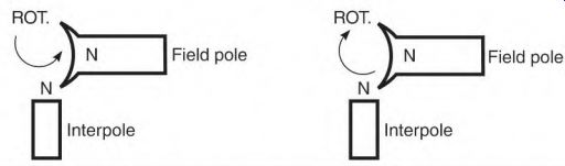
FIGURE 1.32 The polarity and direction of rotation for a generator (left)
and for a motor (right).
Operation of Interpoles
The flux of two magnetic fields becomes distorted if they are close together.
In a DC machine, the armature's magnetic field distorts the stator field's magnetic field. The amount of distortion varies with the change in armature load amperes. Distorted lines of force become a problem when they are forced into the neutral zone.
Armature conductors in the neutral zone are connected to commutator segments that are being switched by the brushes. The bar-to-bar voltage value should be only a portion of the line voltage. The conductors in this position should not cut lines of force, and there should be no voltage generated in them.
The influence of the armature's magnetic field distorts the lines of force as shown in Fig. 1.33. Armature conductors in the neutral zone cut the distorted lines of force. This creates an unwanted voltage in the conductors.
The unwanted voltage value adds to the line voltage value. The commutator's bar-to-bar voltage now becomes too high. The result is excessive arcing at the brushes.
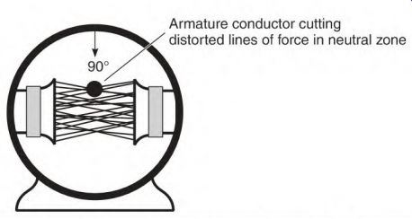
FIGURE 1.33 Magnetic lines of force become distorted by the armature's magnetism.
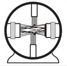
FIGURE 1.34 Magnetic lines of force from the interpoles are cut, creating
a canceling voltage that neutralizes the unwanted voltage (that is produced
by distorted lines of force).
The brushes can be shifted to reduce the arcing, but if the load changes, arcing will again become excessive. One of the reasons brushes arc excessively is that bar-to-bar voltage is too high for the insulation to contain it.
Interpoles are located in the neutral zone. The amperes of the armature go through the interpoles. This creates magnetic lines of force in the neutral zone (Fig. 1.34). These lines of force are cut by the armature conductors generating a voltage in them. This voltage is the opposite polarity of the unwanted voltage described above and cancels it. The result is less arcing.
The polarity of the interpoles is very important. If the polarity is wrong, the voltage generated by them will add to the unwanted voltage instead of canceling it. The bar-to-bar voltage becomes very high, resulting in extremely excessive brush arcing.
The amount of field distortion is directly related to the number of amperes in the armature circuit. With the interpoles connected in series with the armature, the number of lines of force varies with the number of armature amperes. This automatically creates the right amount of canceling voltage needed to minimize brush arcing.
Interpoles must have exactly the right number of turns of wire. If the number of turns required involves a fraction of a turn, the next higher number of turns is used. In this case, nonmagnetic shims are placed under the iron of the interpole. They fine-tune the interpole's magnetic field to the exact strength needed.
Nonmagnetic shims are equivalent to increasing the air gap (the distance between the pole iron and the armature). Increasing the air gap weakens a pole's strength. Use of the nonmagnetic shims allows the pole strength to be weakened and still keeps the same air gap for all interpoles.
DC motor manufacturers custom-fit the interpole iron and shims. If they are disassembled, it's very important that the shims and pole iron be put back in their original location.
The Compensating Winding
The compensating winding (Fig. 1.35) is an extension of the interpoles. It is in series with the armature and is part of the interpole circuit. It brings the effect of the interpoles out to the center of the field pole iron. (This is necessary for motors with a large bore diameter and wide load variations.) When there is a sudden load change, the interpole's influence alone doesn't cover enough pole area to control the arcing.
The compensating winding usually consists of a single turn (a heavy copper bar) embedded in slots (cut in the face of the field pole iron). Because of high current, the end turns and connections of the compensating winding extend beyond the shunt field coils. Any wire carrying high current that is located across a shunt coil's end turns will distort the coil's magnetic field. The result will be magnetic unbalance and brush arcing.
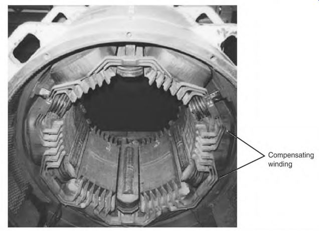
FIGURE 1.35 A compensating winding in a large DC machine. P&H Mining Services.
Operation of a DC Motor
DC generators and motors are interchangeable. Their armature circuits have a large wire and very low resistance and conduct all the ampere output as a generator.
When used as a motor, the low-resistance armature circuit is connected to line voltage. Because of its low resistance, it will demand destructively high amperes. The following text explains how amperes are controlled in a motor's armature circuit. It also compares an armature conductor generating voltage in a generator and the same conductor producing torque in a motor.
One Armature Conductor in a Generator as It Passes Two Poles
In a DC generator, the conductors of the armature cut lines of force provided by the stator fields and produce power. In Fig. 1.36, we can follow one conductor as it travels past the poles of a two-pole stator. The conductor's voltage value changes as its position changes.
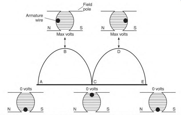
FIGURE 1.36 The amount of voltage (produced by a conductor) changes as it
moves across a pole face.
Each stator pole is equal to 180 electrical degrees, making it possible to describe a location on a pole regardless of a motor's physical size. This particular magnetic circuit consists of two poles. Together they equal 360 electrical degrees.
Figure 1.36 illustrates the voltage values produced by a conductor as it cuts the lines of force of two poles. In position A, the conductor is not cutting lines of force because it is traveling in line with them. (This is the neutral position, where no voltage is produced.) As the conductor moves toward position B, it cuts more and more lines of force, increasing its voltage. When the conductor reaches position B, it will be cutting the maximum lines of force and creating maximum voltage. The conductor is now at the 90° spot of the pole.
As the conductor moves toward position C, it cuts fewer and fewer lines of force until it isn't cutting any lines of force (like position A). As the conductor enters the south pole, it produces an opposite voltage.
At this point, the commutator reverses the polarity of the conductor. The current continues to flow in the same direction as it did in position B (direct current). As the conductor moves toward position D, it cuts more and more lines of force, and its voltage increases. When it reaches position D, the voltage output again is maximum value. As the conductor moves toward position E, it cuts fewer and fewer lines of force until, like position A, position E voltage output is zero. The conductor has moved 360 electrical degrees.
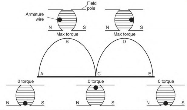
FIGURE 1.37 The amount of torque (produced by a conductor) changes as it moves
across a pole face.
One Armature Conductor in a Motor as It Passes Two Poles
Armature conductors in a DC motor create torque. Their position (as they move across a pole face) determines how much torque is produced. The ampere demand varies with the torque produced.
Figure 1.37 illustrates the torque value that one conductor contributes as it goes by two poles. In position A, no torque is produced because the conductor is traveling in line with the lines of force. When this happens, the conductor doesn't demand power from the line. As the conductor travels toward position B, the torque and ampere demand increase. At position B (90°), both torque and amperes are at their highest value. Torque and amperes decrease as the conductor moves to point C (180°). As the conductor enters the opposite pole, the commutator reverses the direction of current flow. The conductor's torque remains in the same direction. The torque and power demand will increase until the conductor reaches point D (270°, or the 90° spot on this pole), where it reaches its maximum value. Torque and amperes decrease as the conductor moves to point E. At point E, the conductor will have moved 360 electrical degrees.
Counter-voltage
As the armature of a motor turns, its conductors create torque and demand amperes from the power source. A motor's torque and ampere magnitude match a generator's voltage magnitude at the same location on the poles, as seen in Figs. 1.36 and 1.37.
Because the armature conductors are moving in a magnetic field, they are cutting lines of force and generating voltage. The voltage they generate is opposite the polarity of the power source. This is called counter-voltage (counter electromotive force, or counter emf). The counter-voltage value depends on the speed of the armature and the strength of the stator field. The counter-voltage generated (as the motor's armature rotates) cancels an equal amount of line voltage. This lowers the amount of line voltage applied to the resistance of the armature circuit.
Counter-voltage keeps the amperes in the armature circuit at a safe value. The resistance of the armature circuit is so low that, without counter- voltage, the armature winding would be destroyed in a short time.
Counter-voltage Compared to Charging a Battery
Amperes controlled by counter-voltage can be compared to a battery being charged. (When a battery charger is attached to a dead battery, high amperes flow.) High amperes flow in a DC motor (Fig. 1.38a) when the armature is stationary and line voltage is applied.
The motor in this example is designed for 100 volts and 2 amperes. The armature has 5 ohms of resistance. One hundred volts divided by 5 ohms results in 20 amperes flowing through the armature at 0 RPM. In Fig. 1.38b the battery voltage is up to 6 volts, or is "half-charged." Six volts in the battery cancel 6 volts of the charger, and the amperes drop. This compares to a motor turning at half-speed (Fig. 1.38b). At half-speed, the motor is generating 50 volts of counter-voltage. Fifty volts of counter-voltage cancels 50 volts from the line. Fifty volts divided by 5 ohms lowers the motor amperes to 10 amps.
Figure 1.38c shows the battery nearly charged with 11 volts. This cancels all but 1 volt of the charger, resulting in low amperes. This compares to the armature turning at its rated speed. In Fig. 1.38c, all but 10 volts are canceled by counter-voltage. This leaves 10 volts against 5 ohms of resistance in the armature, allowing 2 amperes to flow. This is the motor's full-load ampere rating.
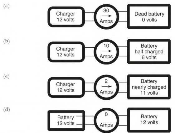
FIGURE 1.38 (a) A comparison is made between a dead battery getting charged
and a loaded motor starting up. (b) A battery that is half-charged compared
with a motor at half-speed, (c) A nearly charged battery compared to a motor
running (at its rated speed), (d) Two fully charged batteries, connected as
shown, will have no current flow between them.
If two batteries of equal charge are connected parallel (Fig. 1.38d), positive to positive and negative to negative, no amperes will flow between them. Twelve volts in one battery will cancel the 12 volts of the other.
If the motor's armature is somehow rotated fast enough, it generates counter-voltage equal to the line voltage. At this speed, there would be no amperes flowing in the armature circuit. If the armature is rotated even faster, the motor would become a generator.
Counter-voltage in a Motor Armature
The armature circuit has low resistance. When voltage is applied to it, a high inrush of amperes goes through the circuit. This gives the armature enough torque to rotate.
As the armature rotates, its conductors cut the lines of force of the shunt field. This action generates a counter-voltage in the conductors. The amperes of the armature are controlled counter-voltage, the resistance of the wires, and the load.
As the armature gains speed, the counter-voltage increases and cancels more and more of the line voltage. As line voltage is canceled, amperes in the armature circuit go down. This is applying Ohm's Law logic: When volts are lowered, resistance doesn't change, and amperes decrease. At rated speed, only the amperes required by the load and the motor's internal losses are needed. A 500-volt motor develops full power with all but 10 to 15 line volts canceled by counter-voltage.
Ninety-five to ninety-eight percent of the armature circuit's potential current flow is canceled by counter-voltage. Without counter-voltage, high amperes and the resulting heat would destroy the armature. Unloaded, it would accelerate to a destructively high speed.
If the technician isn't aware of counter-voltage, testing the armature circuit will be very confusing. If the nameplate voltage and amperes are used to find the resistance of the armature circuit, the actual resistance is much lower.
Base Speed
Base speed is the number of RPM at full load (with full voltage applied to the armature and field circuits). At base speed, the motor is putting out nameplate horsepower and RPM.
Below Base Speed
Below base speed is accomplished by controlling the current through the armature, with full voltage applied to the shunt field. With the shunt field fully energized, the motor has constant torque (from zero to base speed). Consequently, the motor's horsepower output will increase as the speed increases. This control is also used to start the motor.
Above Base Speed
The above base speed control is used after the motor has reached base speed, with full voltage applied to the armature circuit. As amperes are lowered in the shunt field, its magnetic field is weakened. A weaker magnetic field decreases the number of lines of force.
Fewer lines of force being cut by the armature conductors lowers the counter-voltage. Less counter-voltage allows more amperes to flow in the armature circuit. The motor accelerates to a speed above the original base speed and its speed is stabilized.
A weaker shunt field produces less torque, but with the increase in RPM, the motor still has the same horsepower. The control is also called above base speed control torque control or field weakening control.
The DC motor has constant torque below base speed and constant horsepower above base speed. These qualifications meet the demands of most loads.
Torque of the DC Motor
The DC motor has very good torque characteristics.
The commutator switches one circuit at a time in the armature slots. The slots contain one or more coils (circuits). As these coils are commutated, they control the magnetizing of the slot's iron teeth. As the magnetism in the iron of the armature changes from north to south, it does so one tooth at a time, resulting in a very smooth torque at all speeds.
The Shunt Motor
The shunt motor has two circuits: the armature and interpoles (A1 and A2) and the shunt field (F1 and F2) (Fig. 1.39). (A current control for starting the armature is also illustrated.) Figure 1.40 shows the NEMA standard connection for counterclockwise rotation facing the end opposite the shaft.
The Armature and Interpoles
As shown earlier, the armature leads are identified as A1 and A2. The armature windings produce all of the motor's torque output. The interpoles ensure good commutation.
The Shunt Field
The shunt field leads are identified as F1 and F2. The purpose of a motor's shunt field is to furnish magnetic poles for the armature poles to attract or repel and create torque.
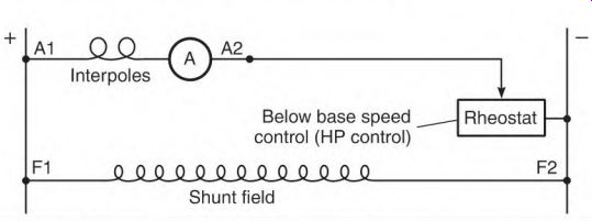
FIGURE 1.39 This schematic of a shunt motor shows the connections and the
armature control.
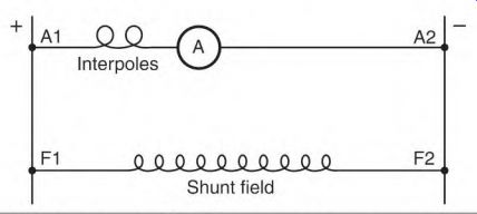
FIGURE 1.40 The NEMA standard shunt motor connection. Rotation is counterclockwise,
facing the end opposite the shaft.
Operation of the Shunt DC Motor
When a shunt motor is started, the shunt field is energized with full voltage.
An armature control puts resistance in series with the armature circuit, limiting the amperes to a nondestructive level. The control allows enough amperes through the armature to start the load. It then lowers the resistance until the motor accelerates to its selected speed.
If the shunt motor isn't loaded, it will accelerate to its no-load speed when full voltage is applied to its circuits. At this speed, counter-voltage allows only the amperes needed for the armature's losses. (This includes bearing friction, the cooling fan load, windage, and the armature circuit's copper losses.) A shunt motor's no-load RPM is higher than indicated on the nameplate.
As the load is applied to the shaft, the armature speed slows down.
The armature conductors now cut fewer lines of force and create less counter-voltage. Less counter-voltage allows more amperes to flow in the armature circuit. The RPM will now stabilize at a lower speed. The load is then increased to the motor's rated horsepower. At full load, the motor will operate at nameplate amperes and RPM.
Starting a Large DC motor with Line voltage will cause excessively high amperes in the armature circuit and will damage the commutator.
If the shunt field disconnects or opens while the motor is running with no load, the armature will accelerate until it is destroyed. The armature will overheat if the motor is loaded and can't accelerate. Without the magnetism of the shunt field, the armature develops very little counter-voltage. Only the resistance of the armature windings will limit the amperes.
The Permanent Magnet DC Motor
A permanent magnet DC motor can withstand vibration and many other adverse conditions better than a motor with wound field coils.
The armature is the only electrical circuit in the permanent magnet DC motor. The stator has permanent magnets fastened to its shell. The permanent magnets aren't as thick as field coils, so the motor has a smaller diameter than the wound field coil motor.
Operation of the Permanent Magnet Motor
The permanent magnet motor operates much like a shunt motor. The magnets furnish torque and counter-voltage (like the coils of the shunt field). The strength of the permanent magnets, however, can't be controlled. If the magnets lose strength, the motor will run faster than nameplate RPM. Loads that require more horsepower (as the speed increases) cause the armature to overheat and fail.
Restoring Magnetism
If a permanent magnet motor runs more than 10 percent above nameplate RPM (with no load), its magnets need to be re magnetized (re-gaussed). Magnetism in a weak magnet can be restored with a stronger magnet. An extremely strong magnet will bring a weak magnet to full strength almost instantly.
Electric motor repair centers use special equipment (a re-gaussing unit and an electromagnet) to re-gausse weak magnets. The re-gaussing unit contains a large number of DC capacitors. When fully charged these capacitors can-for an instant-discharge a very high DC current.
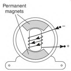
FIGURE 1.41 An electromagnet made for re-gaussing weak permanent magnet motors.
An electromagnet is designed to closely fit the bore of the permanent magnet motor. It's placed in the motor's bore, as illustrated in Fig. 1.41. The re-gaussing unit's capacitors are discharged through the electromagnet's coil-once or twice-creating very strong magnetism. The motor's magnets are almost instantly re-gaussed. The motor is then assembled and test run.
Large permanent magnet motors have magnetizing field coils wrapped around the permanent magnets. These field coils demagnetize and re-magnetize the permanent magnets. (It's very hard to remove the armature unless the permanent magnets have been demagnetized.) After the motor has been repaired and the motor reassembled, DC is applied to the magnetizing field until the permanent magnets are remagnetized. The permanent magnets have full strength when the motor runs less than 10 percent above nameplate RPM with no load. (The magnetizing field leads are separated and insulated when they aren't in use.) The stator's permanent magnets will lose power if the armature is left out of the stator for an extended time. A closefitting rotor, a piece of iron, or another armature should be inserted into the bore. This completes the magnetic path. It's similar to the keeper that is used on horseshoe magnets.
Magnetism can also be weakened if the motor is reversed (plugged) while running. Another suspected cause is rough handling.
The Series Motor
The series motor has two circuits, the armature and interpoles, A1 and A2, and the series field, S1 and S2 (Fig. 1.42).
Figure 1.43 shows the NEMA standard connection for counterclockwise rotation facing the end opposite the shaft.
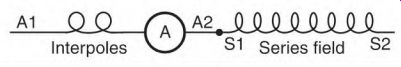
FIGURE 1.42 The circuits of a series motor.
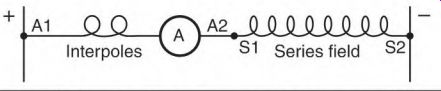
FIGURE 1.43 The NEMA standard schematic of a series motor. Rotation is counterclockwise
facing the end opposite the shaft.
As shown in Fig. 1.43 the two circuits are connected in series with each other. All of the armature amperes pass through the series field. This makes it necessary" to construct the series field coils with wire large enough to carry the full amperes of the motor.
The large wire used in the series field coils makes it a very low-resistance circuit. Amperes through the series field are limited by the counter-voltage developed in the armature. A series field (S1 and S2) should never have the motor's rated DC voltage applied to it.
Operation of the Series Motor
The series motor has very high starting torque. The ampere demand of the armature is very high (at 0 RPM). The same high amperes flow through the series field, resulting in very strong starting torque.
As the armature accelerates, it develops counter-voltage. The counter- voltage lowers the amperes through the armature and the series field. Fewer amperes through the series field lowers the number of lines of force. This lowers the amount of counter-voltage and torque.
The counter-voltage never becomes high enough to control the speed of the series motor, as it does with the shunt motor. Only the load will keep this motor from destroying itself because of high RPM. (Technically, it has no top speed.) A large series motor must have "no-load protection" in its control.
The load is usually direct drive, so this motor must always be loaded.
The starter for an automobile engine is a series motor. Although it's small, it has very high starting torque.
Power tools also have series motors. Gear and bearing friction and a cooling fan keep them from developing excessive RPM.
Compound DC Motor
The compound DC motor has three circuits (Fig. 1.44), the armature and interpoles (A1 and A2), the shunt field (F1 and F2), and the series field (S1 and S2). Figure 1.45 shows the NEMA standard connection for counterclockwise rotation facing the end opposite the shaft.
The Armature and Interpoles
As shown earlier, the armature and interpole leads are identified as A1 and A2. The armature windings produce all of the motor's torque output. The interpoles ensure good commutation.
The Shunt Field
As shown earlier, the shunt field leads are identified as F1 and F2. The purpose of the shunt field is to furnish magnetic lines of force (flux). The armature conductors interact with the shunt field flux to produce torque and counter-voltage.
Interpoles S1 Series field S2
Shunt field
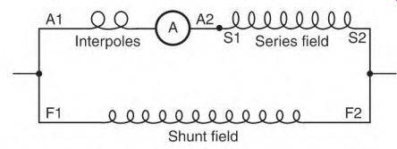
FIGURE 1.44 The compound motor with the armature, interpoles, series field,
and the shunt field.
Interpoles V-X S1 Series field S2
Shunt field
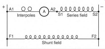
FIGURE 1.45 The NEMA standard connection for the compound motor.
Rotation is counterclockwise, facing the end opposite the shaft.
The Series Field
As described earlier, the series field (S1 and S2) is connected in series with A1 and A2. The armature current goes through the series field, adding magnetic strength to the pole iron. This stabilizes the motor's speed when the load varies.
Operation of the Compound Motor Connected Cumulative Compound
The shunt field is connected in parallel with the armature and series field circuit. Unloaded, the motor starts and accelerates to a speed that is determined by the shunt field. (The shunt field produces enough counter- voltage to stabilize the speed.) As the load is applied, the amperes increase in the armature. The armature current goes through the series field, producing lines of force.
These lines of force are added to the shunt field lines of force, resulting in an increase in field strength and torque. The added strength of the series field stabilizes the RPM as the load is applied. Unlike the shunt motor, this motor doesn't slow as the load increases.
The number of turns of wire in the series field directly affects the amount of stabilizing done.
The flat compound design has enough turns in the series field to raise the RPM as the load is applied. When rated load is reached, the RPM stabilizes at nameplate value. The over-compound design has enough turns in the series field to raise the RPM to a higher value at full load than at no load. This is the more popular design. The motor's control gives it a wide speed range.
The Stabilized Shunt Motor
The stabilized shunt design has very few turns in the series field. The series field is connected differential compound. As the load increases, armature and series field current increases.
The resulting series field magnetism cancels some of the magnetism of the shunt field. This lowers the counter-voltage very quickly and allows more amperes to flow in the armature. The motor will react quickly to sudden load changes. Some efficiency is lost with this design.
Speed Control for a Compound DC Motor
The motor's nameplate shows the base speed of the motor. Figure 1.46 shows a basic compound motor control. Controls can range from hand-cranked rheostats to electronic circuitry. Regardless of their complexity, they will control the components of the motor as illustrated in Fig. 1.46.
Armature Control for Starting and for Below Base Speed
Full voltage should be applied to the shunt field when the armature control is used. Full voltage to the shunt field will give the motor constant torque (from zero to base speed). The armature control allows enough amperes through the armature to give it breakaway torque. The resistance is lowered gradually as the motor starts to accelerate. The motor accelerates to the RPM required by the load. Full voltage is applied to the armature at base speed.
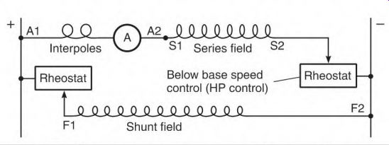
FIGURE 1.46 The basic control for a compound DC motor. The armature rheostat
limits the current for starting and controls the below base speed. It is sometimes
called the horsepower control.
The shunt field control is the above base speed control and is sometimes called the torque control.
Shunt Field Control for Starting and for Above Base Speed
The shunt field control (Fig. 1.46) applies full voltage to the shunt field when the motor starts. The motor accelerates until the RPM is stabilized at base speed. At this RPM the lines of force furnished by the shunt field are at maximum. The amperes flowing in the armature are limited by counter- voltage to a value needed for the load and the motor's internal losses.
The shunt field control (sometimes called above base speed, field weakening, or torque control) can now be used. It adds resistance to the shunt field, lowering the amperes. This will reduce the shunt field's magnetic lines of force or flux. Less magnetism from the shunt field lowers the counter-voltage and allows more amperes to flow in the armature. The result is a higher base speed. The torque is reduced, but increased RPM gives the motor constant horsepower above base speed.
All controls have a field loss feature that shuts the motor off if the shunt field circuit opens. If the shunt field disconnects or opens while the motor is running with no load, the armature will accelerate until it is destroyed. If the motor is loaded and can't accelerate, the armature will burn out. Without the magnetism of the shunt field, the armature develops very little counter- voltage. Only the resistance of the armature windings limits the amperes.
The control components used to control the shunt field are small because of the small number of amperes the shunt field requires.
The shunt field can be excited separately with a different power source.
With separate excitation, the shunt field's supply voltage isn't affected by the high amperes of the armature circuit.
The Differential Connection (Motor)
The connection for the compound motor (described earlier) has the series field connected so that its polarity is the same as that of the shunt field. This connection is called cumulative. It adds the magnetic flux (lines of force) of the series field to that of the shunt field, enabling the motor to maintain stable RPM as the load changes.
When the series field polarity is opposite that of the shunt field, the connection is called differential. With the differential connection (Fig. 1.47), the series field has an effect that is opposite that of the cumulative connection (instead of adding to the shunt field magnetism, the series field reduces it).
As the load increases, the series field amperes increase. If connected to the opposite polarity as the shunt field, the series field's flux (lines of force) cancels an equal amount of shunt field flux. This reduces the lines of force being cut by the armature conductors, lowering the counter-voltage.
Lower counter-voltage allows the amperes through the armature to increase. Higher armature amperes will accelerate the motor to a higher speed. Higher speed increases the counter-voltage, lowering amperes in the armature and series field circuit.
Differential Connection (a)
Shunt field Cumulative Compound Connection (b)
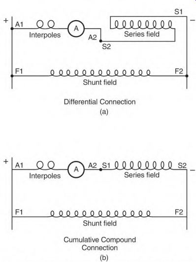
FIGURE 1.47 In the differential connection (a) the series field is connected
opposite that of the shunt field. The cumulative connection (b) is used unless
the series field is designed for the differential connection.
The (fully energized) shunt field flux quickly brings the armature speed back down. When the load demand again slows the armature, the cycle starts again. The result is wide swings in speed.
Armature Components
Commutator
Commutator film
Armature windings
Equalizer shunts
Laminated iron
Commutator
The commutator is made of copper segments that are separated and insulated with mica. The commutator segments function as one side of a switch, and the brushes function as the other. Together they control the direction of the current flow (similar to a diode). The commutator's function is to control the polarity of the coils connected to its segments.
As the armature turns, two commutator segments (and the coil attached to them) have current flow in one direction. The coil is now part of pole A (Fig. 1.48). When the coil's segments go under a brush, they short together, causing line current to stop flowing in the coil.
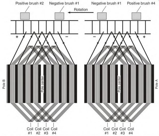
FIGURE 1.48 The commutator bars and armature coils flattened to illustrate
how a single coil's polarity is switched to form poles that are similar to
stator poles.
When the coil's segments come out from under the brush, the current is reversed, and the coil is now part of pole B-the opposite polarity pole in the direction of rotation. No matter how fast the armature turns, the poles in its iron will remain in the same position (relative to the stator poles). The commutator and brushes are high-maintenance components because of friction and electrical wear. (Electrical wear is caused by constant switching.)
Commutator Film
Good film is a very important part of the commutator function. It conducts current and provides lubrication between the brushes and the copper segments. The film shouldn't be removed unless the commutator is reworked.
It takes from several hours to several days to reestablish the film. During this time, the brushes and the commutator are wearing excessively.
The film has some resistance, and removing it will increase the voltage output of a generator and increase the speed of a motor. Slightly better performance, however, isn't worth the amount of increased wear to both brushes and commutator.
The film is roughly 1/1000 the thickness of a human hair. Elements of the film include carbon, graphite, copper oxide, and water vapor. Carbon, graphite, and copper oxide are current-conducting elements of the film.
Water vapor and graphite provide lubrication. The brushes and commutator need a good balance of these elements for maximum life.
Lack of oxygen lowers the copper oxide element of the film, reducing its current-carrying ability. This occurs in totally enclosed and explosion-proof machines.
Dry weather reduces the water vapor content of the film, resulting in increased wear.
There is no "best color" for the film, and it can vary from machine to machine. The color can vary from tan to black and still do a good job.
A color difference in several adjacent bars (Fig. 1.49), with this pattern repeated all around the commutator, doesn't indicate a problem. It means there is more than one circuit (or coil) per slot. As the armature rotates, the circuits in this slot are commutated at a slightly different position (relative to the field poles). If the bars commutate in different positions, each bar commutates a different current value. (This causes each bar to have a different color.)
The color pattern should be the same around the commutator. A difference in the color pattern may indicate a problem.
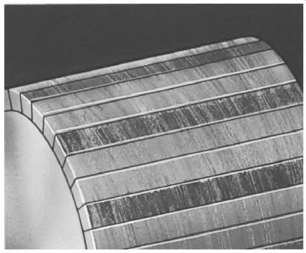
FIGURE 1.49 Slot bar marking caused by a number of circuits in the armature
slots. Helwig Carbon Products, Inc.
If there is bar etching, it can be reduced by moving the brush holder slightly less than one segment. Move the brush holder against rotation if it's a motor and with rotation if it's a generator.
Armature Windings
Armature windings are made with large wire. Most of the amperes flow through the armature in a motor. All of the output amperes flow through the armature in a generator.
Lap and wave are the two basic connections for the armature windings.
The lap connection has as many brushes as there are poles. The wave connection has half as many brushes as there are poles.
Whatever the connection, the poles are precisely spaced and balanced magnetically. Most windings have the same number of turns per slot. If they" don't, the total turns per pole will be the same. This fact makes it possible to use the comparison test when troubleshooting.
Equalizer Shunts
Equalizer shunts (back connections) are used to balance the effects of voltage unbalance in the armature windings. They are placed in the commutator's wire slots or risers. They join segments located under like pole brushes.
Unbalanced voltage will occur between a brush and its two adjacent brushes (Fig. 1.50). The resulting current will flow in the equalizer shunt wire instead of the brushes and commutator. At full load, the commutator is already carrying its rated amperes.
Without equalizer shunts, the amperes caused by unbalanced voltage adds to the full-load amperes. The resulting commutator damage is the same as if some of the commutator bars were overloaded. High current in these bars will cause them to discolor and erode. Bar erosion will eventually cause a flat spot on the commutator.
Laminated Iron
Laminated iron is the magnetic path for the armature. The laminations are thin because of a high-frequency magnetic polarity change in the iron teeth.
The teeth in a high-speed DC armature will have a polarity change well over 100 cycles per second.
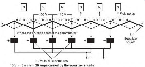
FIGURE 1.50 Equalizer shunts connected to like polarity commutator bars.
A thin coat of insulation separates the laminations. If the laminations are shorted together, eddy current is generated. This current will develop a hot spot in the laminations that will damage the adjacent slot insulation.
Repair centers always core test and, if necessary, re-insulate the laminations before rewinding an armature.
Section 1 Review
1. Voltage ()
a. causes current to flow.
b. must have heavy wire for high voltage.
c. must have current flow to exist.
2. Voltage value determines the thickness of the insulation (). T F
3. Heavy copper wire has no resistance (). T F
4. Resistance controls the voltage (). T F
5. Name two forms of resistance ().
6. Ampere flow is controlled with voltage value and resistance value (2-3). T F
7. Two factors for determining wire size are: the number of amperes and the cooling capability of the device (). T F
8. Amperes can be controlled (up or down) without changing the voltage or resistance (2-3). T F
9. As its heat increases, copper will have (5)
a. more resistance.
b. less resistance.
10. Ohm's Law proves that, as voltage increases, amperes go up (if the resistance stays the same) (5). T F
11. A watt is a measurement of power consumed (5). T F
12. As watts go up, amperes go down (6). T F
13. The number of watts determines the required wire size (6). T F
14. Magnetic lines of force go through air and insulation (6). T F
15. Strength of an electromagnet is controlled by the number of amperes flowing through its coils (6). T F
16. Polarity of an electromagnet is controlled by the number of amperes flowing through its coils (6). T F
17. One north pole and one south pole in a six-pole motor equal electrical degrees (6-8). 18. A six-pole motor has mechanical degrees (8).
19. A two-pole motor has electrical degrees (8). 20. The strength of an electromagnet is controlled by the number of amperes that flow through its coils, and the number of turns (9). T F
21. The magnetic strength of a pole with 10 turns, and 10 amps flowing through it, is the same as a pole with 20 turns, and 5 amps flowing through it (9). T F
22. A complete magnetic circuit is vital to the operation of a motor or generator (9-10). T F
23. All motor and generator poles resemble an electromagnet (0). T F
24. Magnetic saturation is reached when the iron in a motor or generator is fully magnetized (ii). T F
25. Magnetic balance requires that all poles have the same strength, and that they are equally spaced in a machine (2). T F
26. The neutral spot in all stators is located equal distance from adjacent pole centers. T F
27. When the armature poles align with the stator poles, the brush setting is correct (3). T F
28. Name the three basic circuits of the DC machine (13-14). 29. The armature creates in a generator and in a motor (4). 30. The voltage output of a generator is controlled by the number of conductors in its armature circuit, the number of lines of force, and the speed at which the armature conductors cut the lines of force (4). T F
31. Draw the connection schematic of a shunt generator (5). 32. Amperes determine the size of wire used in an armature winding (6). T F
33. The length of the wire in the coils of the shunt field controls the amperes (6). T F
34. What is the purpose of residual magnetism (17-18)? 35. Lowering the amperes in the shunt field raises the voltage output (9). T F
36. The series field coils are made of heavy wire because all of the ampere output goes through this circuit (9). T F
37. A series generator with no load will produce full voltage (9). T F
38. Draw the NEMA standard connection for a compound generator (0). 39. The purpose of the series field in a compound generator is to stabilize the voltage output (2). T F
40. The power output of an over-compound generator is controlled downward by a control (2). T F
41. Diverting some series field amperes will reduce the series field's ability to increase the generator's output (2). T F
42. The cumulative compound connection in the compound generator reduces the voltage output when the load increases (2). T F
43. The differential compound connection in the compound generator reduces the voltage output when the load increases (3). T F
44. The series field is connected the same in a motor as in a generator (4). T F
45. An arc welder is connected differential (5). T F
46. The shunt field of a welder is separately excited (6). T F
47. Selecting a tap that adds more turns to the series field will increase the amperes (26-27). T F
48. A reactor in the welder's circuit bucks sudden changes and makes welding easier (7). T F
49. Interpoles are connected in the armature circuit (A1 and A2) (7). T F
50. The polarity of interpoles in a generator will be the same as the field poles behind them (in the direction of rotation) (8). T F
51. The polarity of interpoles in a motor will be the same as the field poles ahead of them (in the direction of rotation) (8). T F
52. Interpoles create a canceling voltage that decreases brush arcing (29-30). T F
53. What happens when the interpoles are connected wrong (0)? 54. If interpoles are removed from a stator, it is vital that they (and their shims) be reassembled exactly as they were originally (0). T F
55. The compensating winding is necessary in machines that have large bores, and that have sudden load swings (0). T F
56. What controls the amperes in a motor that is running at full speed (4)? 57. Why is there no ampere flow between batteries that have equal voltage (5)? 58. Counter-voltage controls amperes in the armature circuit of a motor (6). T F
59. If a motor's armature is rotated fast enough, it becomes a generator (5). T F
60. Define base speed (6).
61. Below base speed is achieved by reducing the armature amperes, and applying full voltage to the shunt field (6). T F
62. Above base speed is achieved by applying full voltage to the armature, and reducing the strength of the shunt field (6). T F
63. A motor's torque is reduced when the shunt field is weakened (7). T F
64. A motor's horsepower remains the same when the shunt field is weakened and the RPM increase (7). T F
65. RPM of a shunt motor are higher with no load than it is with full load (8). T F
66. Large DC motors will suffer commutator damage if started across the line (9). T F
67. An open shunt field will cause a motor (with no load) to stop (9). T F
68. The speed of the permanent magnet motor will increase if the magnets become weak (9). T F
69. The permanent magnet's strength is acceptable if the motor runs 20% higher than its nameplate RPM (9). T F
70. A permanent magnet's strength can be restored almost instantly with a re-gaussing unit (40). T F
71. A series motor's field can have full voltage applied to it (like a shunt field) (41). T F
72. The series motor has low starting torque (41). T F
73. The series motor's torque decreases as its RPM increases (41). T F
74. What is the series motor's top speed (41)?
75. Draw the NEMA standard connection for a compound DC motor (42).
76. The no-load speed of the compound motor is determined by the shunt field (43). T F
77. The stabilized shunt motor is connected differential to make the motor react quickly to load changes (43). T F
78. The stabilized shunt makes a motor more efficient (43). T F
79. Starting a motor and below base speed both require limiting the current in the armature circuit (44). T F
80. If the shunt field amperes are limited when the motor starts, the amperes of the armature become excessively high, and the torque is lowered (44). T F
81. Connecting a cumulative compound connected motor differential can cause erratic speed swings when it's loaded (45-46). T F
82. The commutator is one side of a sliding switch (that acts as a diode) (47). T F
83. Commutator film should be cleaned off at regular intervals to lengthen the life of the commutator (48). T F
84. Armature windings carry most, and sometimes all, of a DC machine's amperes (49). T F
85. Equalizer shunts connect commutator segments that are located under like pole brushes (50). T F
86. Laminated iron reduces eddy current (50). T F