AMAZON multi-meters discounts AMAZON oscilloscope discounts
Nearly all commercial and domestic power consumed in the United States is AC. High-voltage AC power is carried great distances by power lines, with minimal power loss. Very little power is lost transforming AC to the voltage value required by a consumer. AC is much more versatile and practical than DC power. AC induction motors require much less maintenance than DC motors because most have no commutator. The variable-hertz drive gives the three-phase induction motor speed control that is almost as good as that of the DC motor.
Generating Alternating Current
The operation of most AC motors is affected by the way AC power is produced. For this reason, the generating of AC power will be explained first.
AC alternators (also called generators) consist of a DC-excited rotor and a stator winding. Figure 3.1 shows a single-phase alternator. The stator has one winding or phase.
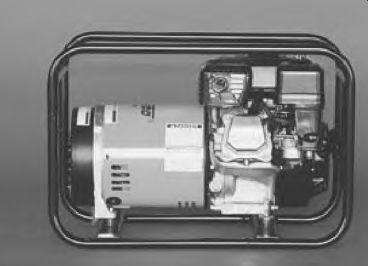
FIGURE 3.1 A single-phase alternator. Winco, Inc.
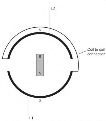
FIGURE 3.2 Basic components for generating alternating current (a bar magnet
and a two-pole field).
In an AC alternator (Fig. 3.2), the conductors of the stator poles are cut by magnetic lines of force (flux) provided by rotating DC field coils. For clarity, a magnet will be used in the following explanation. The magnet will travel past two poles of the stator. As the magnet travels past the first stator pole, its magnetic flux cuts the conductors of the pole's coils, producing a voltage.
In Fig. 3.3 the magnet is in the neutral position between the poles. As the magnet advances, its flux cuts the conductors of each stator pole, and voltage is produced in them. The voltage (output) value will increase (Fig. 3.4) until the magnet becomes aligned with the stator poles. The voltage is now at peak positive value. As the magnet moves out of alignment, the voltage decreases.
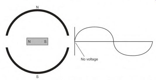
FIGURE 3.3 The bar magnet in the neutral position, where no voltage is generated.
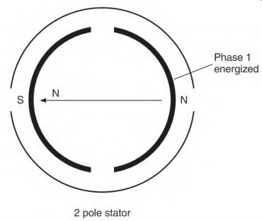
FIGURE 3.4 The magnet's position when maximum voltage is produced.
When it again reaches the neutral position, the voltage is zero.
When the magnetic flux cuts the next pole (Fig. 3.5), the voltage output is negative. When the magnet becomes aligned (Fig. 3.6) with the stator poles, the output voltage is at its highest negative value. As the magnet moves out of alignment, the voltage output decreases until it is again in the neutral position. (One cycle of power has been produced.)
Cycles and Hertz
The number of cycles produced in 1 second is the power's frequency. If one cycle of power is produced in 1/60 of a second, the frequency of the power is 60 cycles per second (60 Hz). The word hertz (Hz) is used instead of the phrase cycles per second.
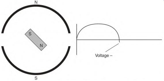
FIGURE 3.5 As the magnet enters the area of the opposite polarity, the voltage
produced changes polarity.
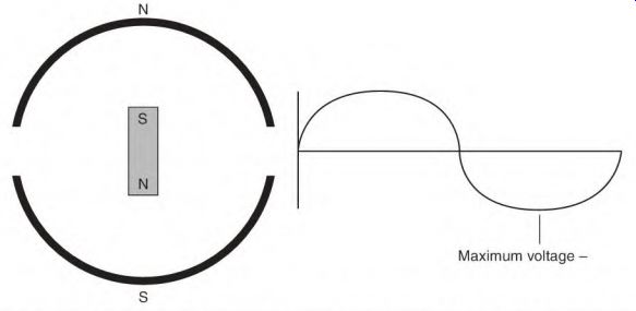
FIGURE 3.6 Maximum voltage (of this polarity) is produced at this spot.
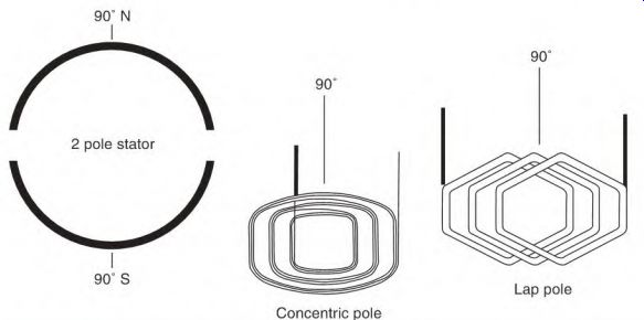
FIGURE 3.7 The center of a pole is the 90 electrical degree spot.
Electrical Degrees and Time
Electrical degrees are used as a reference in electrical machines. Electric motors and alternators both have their poles arranged in a circle. The poles are placed symmetrically and precisely in the circle. Each pole equals 180 electrical degrees.
Electrical degrees are used to describe a location on a pole. The center of a pole is 90° from the edge of the first coil of a pole (Fig. 3.7). This reference point is where a single-phase motor's start-winding pole is placed in relation to the run-winding pole (Fig. 3.8). Three-phase machines separate the phases 120° apart (Fig. 3.9).
One cycle of alternating current is produced by passing a magnet over two (180°) poles of a phase. One cycle is equal to 360 electrical degrees.
The time taken to produce one cycle is also expressed in degrees (Fig. 3.10). Electrical degrees are used to specify the exact time (in relation to the voltage) that something occurs during a cycle. For example, if amperes and voltage are out of step (explained under "Inductive Reactance," later in the section), electrical degrees are used to describe the length of time that they are separated.
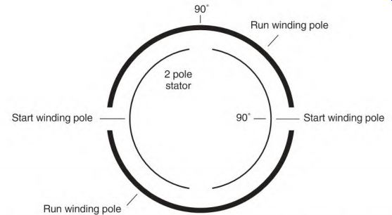
FIGURE 3.8 The start-winding coils are located on both sides of the 90° spot
of the run-winding pole.
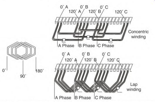
FIGURE 3.9 Three-phase poles are located 120 electrical degrees apart.
Peak voltage positive = 140% of meter reading
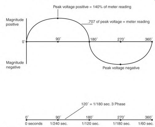
FIGURE 3.10 The sine wave includes voltage magnitude and the time it takes
to produce it.
The word angle is used to describe the amount of separation (in time). An example is phase angle (phase means winding and angle means time).
Electrical Degrees and Mechanical Degrees
Two stator poles produce one cycle of power. Each pole contains 180 electrical degrees. A two-pole stator has the same number of electrical degrees as mechanical degrees. In a four-pole stator, there are 720 electrical degrees in the 360 mechanical degrees of the stator (Fig. 3.11).
Degrees and Location
Degrees are also used to reference a location on a pole. An example of this is the position of the start and run windings of a single-phase stator (Fig. 3.12). The 90° spot of a run-winding pole is the center of the pole (Fig. 3.7). The start-winding coils are located on either side of this spot (Fig. 3.8). Three single-phase windings of a three-phase motor are located 120 electrical degrees apart (Fig. 3.9).
Two-Phase Power
A two-phase alternator is shown in Fig. 3.13. There are two identical single- phase windings located 90 electrical degrees apart. When a DC field is rotated in this stator, two out-of-step voltages are produced. The two voltages are separated by 90 electrical degrees in time (1/240 second at 60 Hz).
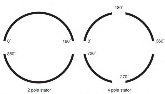
FIGURE 3.11 The two-pole stator has 360 mechanical degrees and 360 electrical
degrees. The four-pole stator has 360 mechanical degrees and 720 electrical
degrees.
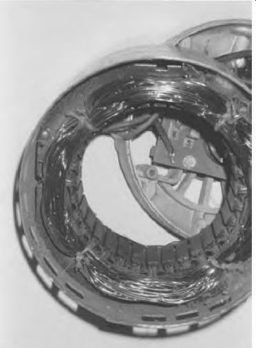
FIGURE 3.12 The stator of a four-pole single-phase motor. Marathon Electric.
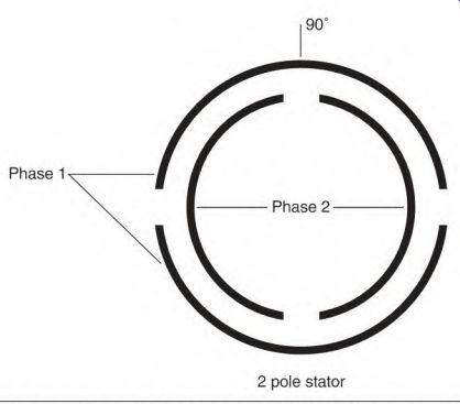
FIGURE 3.13 A two-phase motor has two identical phases spaced 90 electrical
degrees apart.
Two-Phase Rotating Magnetic Field
When 60-Hz two-phase voltage is applied to the windings of a two-phase motor, the peak magnetic strength of its two windings will occur 1/240 second apart. This creates a rotating magnetic field in the stator.
The motor's rotor will try to rotate at the same speed as the two-phase alternator's DC field. Varying the speed of the alternator will vary the speed of the motor.
The rotating magnetic field of an AC motor is created when the current flows in each phase at a different time. When the time (in electrical degrees) that current flows in each phase matches the location (in electrical degrees) of the poles in each phase, the rotating magnetic field is at its effective best.
Figure 3.14 shows a two-pole, two-phase stator with a compass in its bore.
Energizing phase 1 with low-voltage DC will cause the compass to align as shown in Fig. 3.14. Energizing phase 2 with the same polarity moves the compass needle 90° as shown in Fig. 3.15. Reverse the DC polarity and apply it to phase 1. The compass moves another 90° as shown in Fig. 3.16. Apply the reversed polarity to phase 2 and the compass needle aligns as shown in Fig. 3.17. Reverse the DC polarity and apply it to phase 1, and the needle will have made a complete revolution. This is a simplified version of the rotating magnetic field that occurs when two-phase voltage is applied to a two-phase winding.
FIGURE 3.14 A two-phase stator with a compass needle (aligned with energized
phase 1).
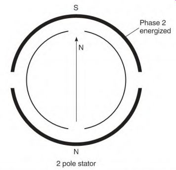
FIGURE 3.15 When energized, the compass needle moves 90 electrical degrees
and aligns with phase 2.
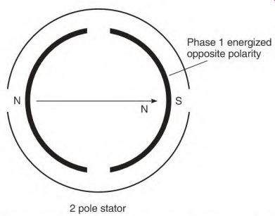
FIGURE 3.16 Reversing the polarity and applying it to phase 1 aligns the compass
needle as shown.
Revolutions per Minute, Poles, and Hertz
The cycles per second (Hz output) is determined by the speed at which the AC alternator is driven and its number of poles.
The synchronous RPM of most AC motors is determined by the number of poles and the Hz of the power source. The following formulas give the synchronous speed of AC induction and synchronous motors:
Hz x 60 seconds (to get cycles per minute) x two poles = numerator
Numerator -p poles = RPM Numerator h- RPM = poles 60-Hz numerator = 7200 A two-pole motor on 60 Hz: 7200 -p 2 poles = 3600 RPM
Two-pole synchronous speed (at any Hz) divided by the motor's pairs of poles = synchronous speed of the motor: For 60 Hz: 3600 -p pairs of poles = RPM For 50 Hz: 3000 pairs of poles = RPM

FIGURE 3.17 Applying the reversed power to phase 2 completes one revolution.
The Single-Phase Alternator
Single-phase power is generated when a DC magnet is rotated past a single- phase winding (Fig. 3.18). As the magnet starts across a single-phase pole, the voltage generated builds to its peak value when the magnet and the pole are aligned. The voltage value drops to zero as the magnet goes past center and exits the pole. As the magnet enters the next pole, the voltage generated is of the opposite polarity. The voltage value will increase to a peak value and then decrease to zero.
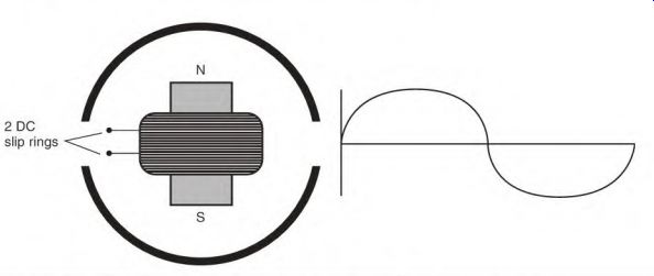
FIGURE 3.18 Basic principle of generating single-phase power.
Current, Ampere, Power, and Reactive Terms
Many combinations of terms are used with current amperes and power.
Current, amps, and amperes are used interchangeably. Current is used to describe the fact that amperes of some type (lagging, leading, in unity with voltage) are flowing in a circuit. Ampere flow (or amps flowing) also signifies current in a circuit.
The current exchange between a coil and the power source may be called magnetizing current, magnetizing amperes, reactive current, reactive amperes, and reactive amps. The current between a capacitor and the power source may be referred to as reactive current, leading current, leading amperes, leading amps, reactive amperes, and reactive amps.
The amperes required to do work, or which are part of a wattmeter's result, are called true amps, true amperes, real amps, and real amperes.
Power terms include apparent power, real power, power factor, lagging or leading power factor, and actual power. All power includes both amperes and volts.
The term reactive can apply to both leading (capacitive) and lagging (inductive) descriptions.
The following text describes the effect different components have on the amperes of a circuit and the condition of a circuit's power.
Inductive Reactance
Inductive reactance is a form of resistance to current flow. Like DC current, alternating current creates a magnetic field around a wire. Alternating current is continually changing in magnitude and polarity. The strength of the magnetic field around a wire changes with the amount of current. The direction of current flow in the wire changes with the polarity of the AC voltage. The polarity of the magnetic field around a wire changes with the polarity of the AC voltage.
When two wires carrying AC current in the same direction are placed next to each other (Fig. 3.19a), there is a bucking interaction between them until their magnetic fields combine into a larger magnetic field (Fig. 3.19b). This interaction will cause the current to flow out of step with and later than the voltage that drives it. This current delay is called inductance. Resistance to current flow caused by inductance is called inductive reactance.
Inductive reactance occurs when there is a changing magnetism.
Inductive reactance can be demonstrated with a length of wire. If the wire is in a straight line, the only significant resistance to AC current flow is the resistance of the wire itself. If the wire is wound into a coil, there will be inductance and inductive reactance (resistance to current flow). If the wire is wound around a loop of iron, as shown in Fig. 3.20, inductive reactance is increased even more.
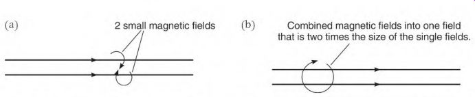
FIGURE 3.19 (a) A magnetic field surrounds each current-carrying conductor.
The fields buck each other while the current magnitude is changing, (b) They combine and form a stronger field. (a) 2 small magnetic fields (b) Combined magnetic fields into one field that is two times the size of the single fields.
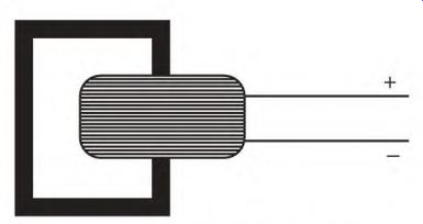
FIGURE 3.20 Iron adds to the bucking action of a coil.
Impedance
Impedance is the sum of the resistance of the conductor and inductive reactance. Inductive reactance furnishes most of the resistance to current flow in an AC motor.
Inductive Reactance and Counter-voltage
Inductive reactance in the windings of an AC motor serves the same purpose as counter-voltage in the armature of a DC motor. The resistance of the windings of a DC armature and the windings of an AC motor are very low.
If DC voltage is applied to an AC winding, there would be no inductive reactance and the winding would be destroyed.
Power Factor
Power factor is defined as the ratio between true power and apparent power.
True power is the power that is actually used by a load. Apparent power is the sum of the true power amperes and the magnetizing amperes (see the upcoming section "Magnetizing Amperes and Lagging Power Factor"). The power factor of a circuit is found by dividing true power by apparent power.
True power amperes can be found with a wattmeter. The meter's reading in watts divided by the applied voltage equals the true amperes.
Amperes, read with an AC ammeter, are the circuit's real power plus its apparent power. A clamp-on AC ammeter displays the sum of the magnetizing amperes plus the true amperes of an inductive circuit. True power amperes of a wattmeter divided by apparent power amperes of an AC ammeter equals the power factor. The result is a decimal value or percentage.
A power factor meter can be used to find the power factor of a circuit. It measures both the voltage and amperes, and computes the result.
The power supplier's watthour meter records and charges for only the real power.
Unity Power Factor
If there is no reactive power, the current and the voltage are in step (Fig. 3.21). The condition is called unity power factor. All the power used at unity power factor is real power and is recorded by the power meter as consumed power. (Power used by resistors or stove elements is at unity power factor.)
Magnetizing Amperes and Lagging Power Factor
When amperes are out of step with the voltage, the circuit has a power factor.
The power factor can be leading or lagging. (Leading power factor is covered under "Capacitor Function," later in the section.) This section explains a lagging power factor and the relationship of current and magnetism in a coil during one cycle.
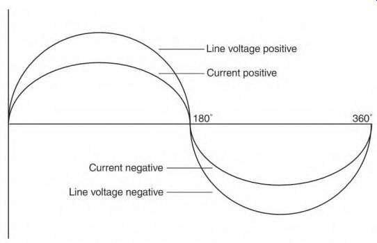
FIGURE 3.21 Current and voltage are in step when there is unity power factor.
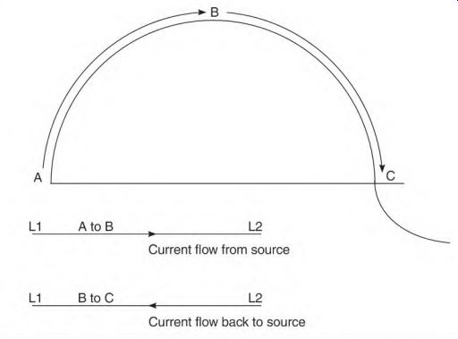
FIGURE 3.22 As current increases, power is drawn from the source (A to B).
When current decreases, power (B to C) is created and flows back to the source.
As current flow increases from point A to point B in Fig. 3.22 through a coil of wire, there is a bucking interaction between the magnetic fields of each turn of wire. The magnetic fields of the entire coil then combine to form a large magnetic field. The power source supplies the current needed to magnetize the coil (magnetizing amps) until peak current (point B) is reached. The current at this point starts to drop toward zero. As the current decreases, the magnetic field starts to collapse. The collapsing magnetic lines of force cut the turns of the coil and create a voltage in them. The power this voltage creates makes current (or magnetizing amps) flow back to the power source. The current cycle now crosses the zero line (point C) and flows in the opposite direction. The coil is now being magnetized in the opposite polarity.
It will draw power and then send it back to the source in the same sequence as the previous half-cycle. With inductance in the circuit, current is out of step with (lagging) the voltage by a number of degrees (which represent time). (The circuit has a lagging power factor as shown in Fig. 3.23.)
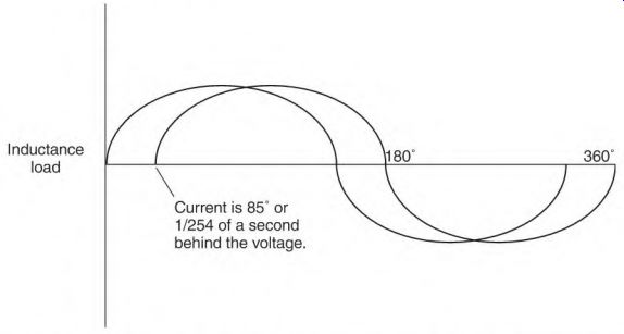
FIGURE 3.23 The result of Figure 3.22 is continuously lagging current, or
power factor.
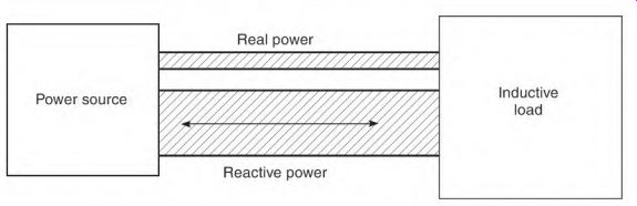
FIGURE 3.24 The difference between reactive power and real power.
The magnetizing amperes do no work. The more inductive components the circuit has, the higher the magnetizing amperes become. In a circuit with a low power factor, the magnetizing amperes may be more than the real amperes.
Power Factor in Motors
Most motors have a lagging power factor because they have coils surrounded by iron. Magnetizing a coil surrounded by iron creates much more inductive reactance than magnetizing a coil alone. The amount of resistance created by inductive reactance is determined by the number of turns of wire and the amount of iron surrounding the coil.
A motor's power factor can change under certain conditions. If the power factor is given on a motor's nameplate, it has been calculated with rated voltage, and with rated load applied. A motor's power factor is lowered if the applied voltage is higher than its nameplate rating or if the motor is underloaded. One or both of these conditions are normal in industry.
Low Power Factor Concerns
The problem created by a low power factor occurs in the supply lines and the power source. Magnetizing current (reactive or magnetizing amps) is added to the load current (true amperes) value (Fig. 3.24). The result is heat loss and voltage drop in the supply lines. Magnetizing amperes add nothing to the power cost and do no work. However, they do require the same number of circular mils (circular mils were explained in Section 1) as the real power amperes.
A transformer large enough to carry a load at unity power factor would overheat if the load's power factor were too low. A 50 percent power factor requires a transformer two times larger to avoid overheating (with the same load). Power suppliers often charge a penalty if they must provide a larger transformer or if they have to install power factor correcting capacitors.
The effect of power factor correcting capacitors is explained later under "Capacitor Function."
122 Electric Motor Maintenance and Troubleshooting
Inductive Reactance and Hertz Change
The amount of resistance created by inductive reactance is related to the amount of polarity change (Hz) of the power source. As Hz go up, so does the resistance of the inductive circuit. The winding of a motor designed for 50 Hz has more resistance on 60-Hz power. With fewer amperes through its winding, the motor has less power than it had with 50 Hz. (As Hz go up, amps go down.) The power change is proportional to the Hz change. If voltage is increased in the same proportion as the Hz increase, the lost power is restored.
Formula for 50-Hz to 60-Hz Power Change
There are two ways to increase a 50-Hz motor's power when it is operated on 60 Hz. One is to rewind the motor using fewer turns. The other is to increase the applied voltage. Both methods increase the volts per turn, which increases the amperes. The following formulas are used to increase the applied voltage:
V60 ^ 50 = 1.095
Increase the voltage 10% 60 50 = 1.2
The square root of 1.2 = 1.095 1.10 x the 50-Hz voltage = the same horsepower but less torque 60 - 50 = 1.2
1.2 x the 50-Hz voltage = the same torque but more horsepower
The increased horsepower will increase the motor's heat, but the increase in RPM will increase the motor's cooling ability. In most cases, the increased cooling compensates for the increased heat.
Impedance in a Three-Phase Winding
There are two forms of resistance to current flow in AC motor windings: resistance of the wire and inductive reactance of the winding. The sum of the resistance and inductive reactance is called impedance.
The following is a hypothetical example of three-phase motor data. It will show the amount of resistance to current flow that inductive reactance has in the total impedance of the motor.
• Hypothetical motor nameplate data: 230 V, 5 A
• Winding data: connection one delta (the delta connection puts each phase across the line).
• Four-pole: three coils per pole group, 25 turns of #\7 wire; each turn contains 1 ft of wire. (^17 wire has 5.05 ohms of resistance per 1000 ft.)
• Impedance of one phase of a four-pole three-phase motor is as follows:
Resistance:
3 coils x 25 turns (1 ft per turn) = 75 ft per pole group 75 ft x 4 pole groups = 300 ft of 17 wire per phase 300 ft -f 1000 ft = 0.3 (multiplier to get resistance of 300 ft)
0.3 x 5.05 ohms = 1.515 ohms (resistance of one phase)
Inductive reactance:
230 volts 5 amperes = 46 ohms of impedance per phase 46 ohms (impedance) - 1.515 ohms of resistance = 44.48 ohms of inductive reactance
If 230 volts DC are applied to one phase: Volts -4- ohms = amps 230 volts 4- 1.515 ohms = 151.8 amps (through one 17 wire)
1.515 ohms 4- 46 ohms = 3.2%
Only 3.2 percent of the resistance to current flow is furnished by the resistance of the winding. Inductive reactance furnishes the remaining 96.8 percent of the resistance.
Capacitance and Capacitive Reactance
Capacitance is the term used to describe a component's or circuit's ability to store electrical energy.
Capacitive reactance is the amount of effect capacitance has on a circuit.
Like inductive reactance, capacitive reactance has resistance to current flow.
Capacitor Function
A capacitor stores power in electrostatic form. As a fully charged capacitor is discharged, power is produced. Unlike inductive reactance, as Hz go up, amperes also go up.
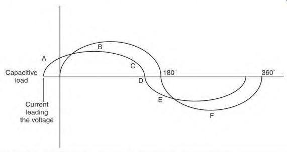
FIGURE 3.25 The changing current's reaction to a capacitor.
The sine wave in Fig. 3.25 shows how the electrons flow in a capacitor.
As the voltage goes up at point A, electrons are pulled into the capacitor plate as if there is a vacuum. When the voltage reaches peak value (B), the electron (current) flow stops because the voltage potential on the capacitor plate equals the voltage of the sine wave. As the voltage value drops (C), the electrons are expelled from the capacitor plate as though they are under pressure. At point D in the sine wave, there is no voltage potential, so there is no electron flow. As the voltage polarity reverses (E), the electrons are pulled onto the opposite plate as though there is a vacuum. At the peak of this half of the cycle (F), electron movement stops. As the voltage drops toward zero, the electrons leave the plate (as though under pressure) until the voltage drops to zero. The vacuum-pressure action results in a separation of the voltage and the current, causing the current to lead the voltage. This is a line condition with a leading power factor. (The current leads the voltage.)
Capacitor Value
The capacitance rating of a capacitor is measured in microfarads (mfd or p). (pi is used instead of mfd on the side of capacitors.) A capacitor's rating is affected by the area of its plates and the thickness of its dielectric (insulation between plates). Increasing the plate area increases the mfd rating. When capacitors are connected in parallel, the plate area is increased. The capacitor's mfd ratings are added together to get the total capacitance value in a parallel connection.
When two identical capacitors are connected in series, the thickness of their dielectric is doubled. This connection reduces the total capacitance value. To get the capacitance value of identical capacitors connected in series, divide the value of one capacitor by the number of them. For example, for two 300-mfd capacitors connected in series, 300 mfd -r 2 (capacitors) = 150 mfd.
Capacitors for Single-Phase Motors
There are many types of capacitors. The two types discussed here are used in single-phase motors-oil-filled and electrolytic capacitors (Fig. 3.26). Both have two plates made of aluminum. The aluminum plates are separated by insulation called a dielectric. The plates and dielectric are rolled up tightly and placed in a container.
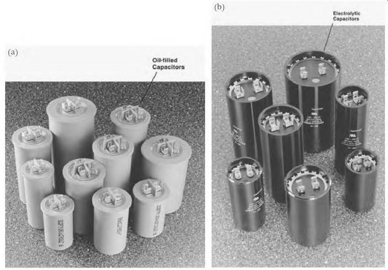
FIGURE 3.26 (a) Oil-filled capacitors used in motors. Aerovox. (b) Electrolytic
capacitors used in motors. Aerovox.
Oil-Filled Capacitor Oil-Filled Capacitor in Single-Phase Motors
The oil-filled capacitor is used to improve the power factor of capacitor-start, capacitor-run motors. In a permanent-split capacitor-run motor it will shift the current flow of the start winding ahead (in time) of the current flow in the run winding. The result is a rotating magnetic field.
Oil-Filled Capacitor Components
The oil-filled capacitor has two aluminum plates that are separated by a thin sheet of plastic. The aluminum plates are very thin because this type of capacitor limits the amperes to a low value.
Aluminum is melted and sprayed on the plastic dielectric to form the plates. This results in a rough surface, which increases the plate area for a given length of dielectric. This design reduces the overall size of the capacitor.
The physical size of the oil-filled capacitor is very large compared to the electrolytic capacitor. This is because the dielectric of an oil-filled capacitor is much thicker than the dielectric of an electrolytic capacitor.
The oil-filled capacitor is designed for continuous service. The oil is used to cool the capacitor. The plates and dielectric are rolled tightly, insulated, and sealed in a metal container filled with oil.
The voltage rating of oil-filled capacitors should be at least twice that of the motor.
Oil-Filled Capacitor Connection in a Two-Value Capacitor Single-Phase Motor
The oil-filled capacitor is used to improve the power factor of a single- phase motor. It's connected in series with the start winding (Fig. 3.27). They are always connected in parallel with the start switch contacts and the electrolytic capacitor. If two or more are used, they are always connected in parallel with each other and are never connected in series.
The start contacts are open when the motor is running. The electrolytic capacitor is now disconnected. There is now a circuit from line 1-through the oil-filled capacitor and the start winding-to line 2. The amperes through the start-winding circuit are leading the voltage. This reduces the magnetizing amperes caused by the run winding's low power factor. The number of leading start-circuit amperes is subtracted from the amperes of the run winding. Figure 3.28 shows the amperes of each circuit, with the result displayed on the line ammeter. If the capacitance is doubled, as in Fig. 3.29, the start-winding circuit amperes are doubled. The run-winding amperes stay the same, and the line amperes are correspondingly less.
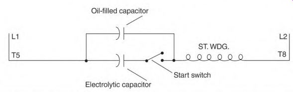
FIGURE 3.27 The oil-filled capacitor is connected in series with the start
winding.
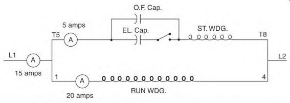
FIGURE 3.28 The effect that an oil-filled capacitor has on amperes of a motor.
10 amps
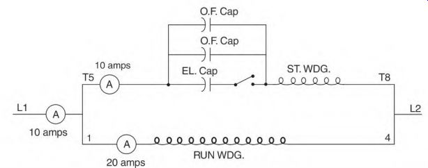
FIGURE 3.29 Line amperes (magnetizing amps) go down as more capacitance is
added.
The ampere values in the preceding illustrations are exaggerated. In reality the start winding would get hot and char if amperes were too high for its wire size.
Mounting the Oil-Filled Capacitor
Use caution when mounting the oil-filled capacitor. Be sure the lid is free to move.
When the dielectric of oil-filled capacitors breaks down, an arc forms between the plates. The arc vaporizes the oil and causes the container to swell, rupture, and possibly catch fire. The lid of the container is designed so that it automatically disconnects the capacitor, therefore eliminating the problem.
The lid contains the external terminals, as shown in Fig. 3.30. When it's in place, a protrusion under the terminals presses against the lead straps of the plates. The lid moves upward when vaporized oil has caused the container to expand. The terminals are then automatically disconnected from the plates.
Electrolytic Capacitors
Electrolytic Capacitor Function in the Capacitor-Start Motor
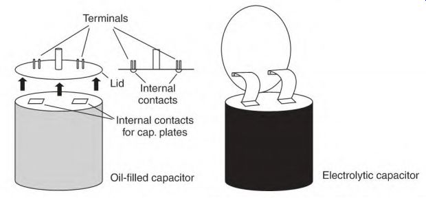
FIGURE 3.30 The oil-filled capacitor disconnects itself when the lid is forced
away from its internal contacts. The electrolytic capacitor isn't sealed and
has straps riveted to the lid terminals.
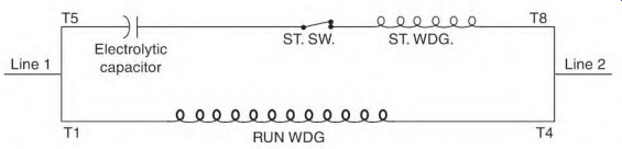
FIGURE 3.31 The "at rest" position of a capacitor-start motor's
start contacts.
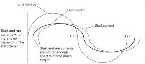
FIGURE 3.32 The currents of the start and run windings have little separation
in time with no capacitor in the circuit. Very little torque is produced. Start
and run currents when there is no capacitor in the start circuit.
Figure 3.31 shows the motor circuitry in the start position with the start switch contacts closed. When the motor is energized, it will accelerate to approximately 75 to 80 percent of synchronous speed in about 1 second. At this time, the switch contacts open, shutting off the start-winding circuit. The motor now operates with only the run or main winding energized.
Electrolytic capacitors (of the correct size) help create a rotating magnetic field that starts the motor. They control when current flows in the start-winding circuit (in relation to current flow in the run winding). The sine wave in the following illustrations shows why the capacitor has to be the right size.
In Fig. 3.32, there are no capacitors in series with the start winding. The sine wave shows the position of the line voltage, the start-winding amperes, and the run-winding amperes.
Run windings and start windings both have inductance. The run winding usually has more turns and is located deeper in the iron (slot) than the start winding. Both factors (more turns and deeper in the iron) give the run winding more inductive reactance than the start winding. More inductive reactance in the run circuit causes the amperes to flow slightly later than the amperes of the start circuit. This small difference in time between the start and run currents means the motor will have very little starting torque.
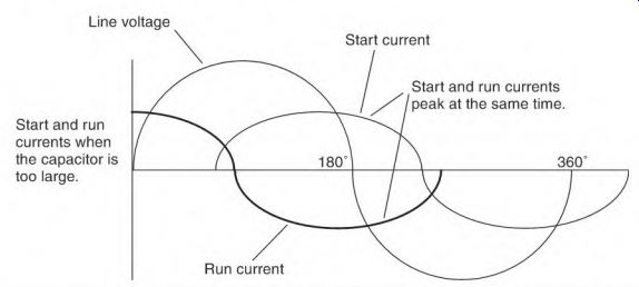
FIGURE 3.33---The effect is the same with too much capacitance as with no
capacitance.
Figure 3.33 is an example of too much capacitance. In this illustration, the two currents are flowing at nearly the same time. The result is little or no starting torque.
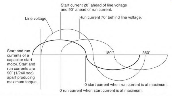
FIGURE 3.34---The ideal current separation (90°) matches the 90° offset position
of the start and run windings. Start and run currents of a capacitor start
motor. Start and run currents are 90° (1/240 sec) apart producing maximum torque.
Line voltage Start current 20° ahead of line voltage and 90° ahead of run current.
Run current 70° behind line voltage. 0 start current when run current is at maximum.
0 run current when start current is at maximum.
Figure 3.34 shows an ideal amount of separation. The separation is 90 electrical degrees or 1/240 second on 60-Hz power. Ninety degrees separation in the current matches the 90 physical degrees of separation between the start and run windings. This timing is accomplished using capacitor(s) of the right size in series with the start winding.
Electrolytic Capacitor Components
The plate area of the electrolytic capacitor is small compared to the oil-filled capacitor. The aluminum plates are thick because the electrolytic capacitors are designed for high current. Paper impregnated with a solution of water, borate, and glycol separates the plates. The liquid solution is an electrolyte which conducts electrons to one of the plates during each half cycle.
The dielectric of the electrolytic capacitor is the very thin oxidized coating on the aluminum plates. The extremely thin dielectric gives this type of capacitor a very high mfd rating for its size.
The components are encased in a plastic container with the terminals mounted in the lid. Straps of aluminum connected to the plates are riveted to the terminals. A small hole (sealed with rubber) is also in the lid. The rubber seal will rupture and release the pressure (when the capacitor's water boils from overheating).
Prolonged current flow (more than 3 seconds) will make the water solution boil and can cause the electrolytic capacitor to explode.

FIGURE 3.35 The capacitor-start motor's internal connections.
Electrolytic Capacitor and Start-Winding Connections
Electrolytic capacitors are connected in series with the start switch and the start winding as shown in Fig. 3.35. There is no standard sequence for connecting the components of this circuit.
Multiple electrolytic capacitors are usually connected as a single unit in the connection sequence. They are connected either parallel or in series with each other when more than one capacitor is used.
Parallel Electrolytic Capacitor Connection
The parallel connection is shown in Fig. 3.36. The total capacitor plate area is increased with this connection. The mfd value of the capacitors is added to get the total capacitance of the circuit. The mfd rating of the capacitors connected in parallel can be different.
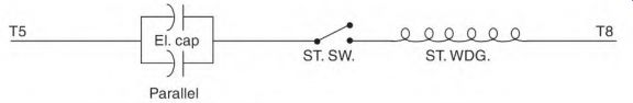
FIGURE 3.36 Parallel connected capacitors.
The capacitor's voltage rating must be as high or higher than the voltage applied to the start-winding circuit.
Capacitors are connected in parallel for two reasons: If a large mfd value is needed, two or more capacitors are easier to mount on the motor than one large one, and it enlarges the capacitor's cooling area.
Heat develops in a capacitor each time the motor starts. Frequent starting may prevent the capacitor from cooling sufficiently. All capacitors have a breakdown voltage value. When voltage reaches this value, it will puncture the capacitor's dielectric and destroy it. As the temperature of the capacitor increases, it takes less voltage to break down the dielectric.
If frequent starting is necessary, a single capacitor can be replaced with two or more capacitors in parallel. (The total value of the parallel capacitors must be the same as the single capacitor's value.) Two or more capacitors in parallel increase the cooling area, allowing more starts per hour.
The highest recommended temperature for capacitors is 150 degr. F. High temperatures dry out the electrolyte fluid. Loss of electrolyte fluid derates the mfd value of a capacitor.
Series Electrolytic Capacitor Connection
The series capacitor connection is used on high-voltage (above 200 volts) motors. When two low-voltage capacitors are connected in series, their dielectric is doubled, allowing the voltage to be doubled. The cooling area of two low-voltage capacitors is larger than that of one high-voltage capacitor.
There are two rules for connecting electrolytic capacitors in series:
• Never have more than two capacitors connected in series with each other.
• When two capacitors are connected in series, they must be labeled the same mfd value.
The reason capacitors must be of the same mfd value is that the voltage divides across them in inverse proportion to their rating. A lower mfd capacitor would have voltage across it that is too high.
Example:
Volts x Cj -h Cj + C2 Line voltage
Capacitor #1 (CJ Capacitor #2 (C2)
= volts across C
= 240 volts
= 200 mfd
= 100 mfd
240V x Cj ^ C1 + C2 = 240V x 200V (CJ 200 + (C2) 100 or,
48,000 + 300 = 160 volts across C2 (the smaller capacitor rated for 120V)
Under normal starting conditions, the voltage developed across the capacitor- and start-winding circuit will be 140 percent of the applied voltage for less than one-half of a cycle. Capacitors of equal mfd rating would have (half of 240 volts) 120 volts x 140 percent =168 volts across each of them.
The voltage across C2 in the above example would be 160 x 140 percent = 224 volts.
The actual mfd rating of the electrolytic starting capacitor is within 10 percent of its stamped rating. If there are two ratings, the actual mfd value will be somewhere in between. Such a small mfd difference isn't critical because it's normally in the circuit for 1 second or less.
Testing the Electrolytic Capacitor
A capacitor's rating can be checked with an electronic test instrument like the one shown in Fig. 3.37. This instrument can quickly give a capacitor's value in mfd. The test uses low energy and is not destructive.
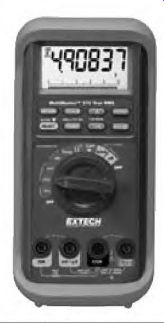
FIGURE 3.37 An instrument for checking a capacitor. EXTECH Instruments.
An ohmmeter can be used to test a capacitor. When testing a good capacitor, it will show a low-resistance reading, which rises slowly until the capacitor is charged.
This test indicates the capacitor has capacitance but doesn't give the amount of capacitance. No reading means the capacitor is open; a steady low-resistance reading indicates it's shorted.
Some internal problems in the electrolytic capacitor aren't revealed by using a low-energy test method. A test method (formula to follow) using line voltage will stress the internal components and determine the capacitor's mfd value. This test will also cause a weak part to break down. (A capacitor has nearly this same amount of stress each time the motor starts.) One of a capacitor's weak spots is under the lid where the lead straps of the plates are riveted to the connection terminals. These straps flex when the capacitor heats and cools, causing them to crack or break at the rivet. The motor occasionally fails to start when this happens. The high amperes of this test method will blow the weak spot open.
Excessive heat dries out the water-based electrolyte in the capacitor. (Too many start cycles per hour is a common cause of overheating.) A thick piece of insulation is needed between the capacitor and the hot motor frame to limit the heat transfer.
A capacitor's mfd rating is lowered when some of the electrolyte evaporates. This condition lowers the capacitor's amperes.
Capacitor Test Formula
The following formula determines the capacitor's exact mfd rating:
[159,300 -r Hz] x [amps -h volts] = mfd
The formula can be shortened to a single number when the Hz value is constant. This number divided by the test bench voltage results in a multiplier. The multiplier times the capacitor's (across the line) amperes value equals the capacitor's mfd rating: 159,300 ^ 60 Hz = 2655
2655 x [amps -f volts] = mfd 2655 -j- volts = multiplier
Multiplier x capacitor amps = mfd
Below are several test bench voltages and multipliers. Apply line voltage to the capacitor and quickly read the amperes. Multiply the resulting amperes and the multiplier for the capacitor's mfd value.
Place a box or pail over the capacitor during this test because the capacitor could explode and cause injury.
2655 -r 110 V = 24 24 x 35 amps = 840 mfd 2655 -f 120 V = 22 22 x 35 amps = 740 mfd 2655 ¦f 130 V = 20.4 20.4 x 35 amps = 714 mfd 2655 -r 230 V = 11.5 11,5 x 20 amps = 230 mfd 2655 •I- ro -P- o V = 11 11 x 20 amps = 220 mfd
Replace the capacitor if test results are 20 percent less than the capacitor's stamped rating.
If 50-Hz power is used, divide 3186 by the test bench voltage.
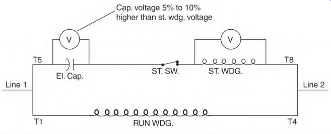
FIGURE 3.38 Schematic for determining the right size capacitor.
Determining the Right Size Capacitor
Figure 3.38 shows the connection used to find the right size capacitor for a capacitor-start motor. However, the sequence of the start-circuit components isn't always as shown in this diagram.
NEMA identification numbers for start-winding leads are T5 through T8.
The capacitor terminals are usually accessible, but the location of the start winding isn't always visible. An ohmmeter can be used to locate the start winding. Disconnect one of the capacitor leads to make sure it isn't in the circuit. Place one probe on the disconnected capacitor lead and the other on T5. If there's no reading, put the probe on the other capacitor lead.
If there is a reading, turn the motor's shaft. If the start winding is between the probes, a high and low fluctuation will show on the ohmmeter. If there is no fluctuation, move the probes to the other capacitor terminal and T8, and turn the shaft.
Two voltmeters should be connected (as shown in Figure 3.38) so that the time power applied is kept to a minimum. Lock the rotor, apply the motor's rated voltage, quickly read the two voltmeters, and shut off the power. The voltage read across the capacitor should be 5 to 10 percent higher than the voltage across the start winding. If the voltage across the capacitor is too high, do the test again using a smaller size capacitor.
If the start winding is dual voltage, use the same procedure as just described, with the low-voltage multiplier. Figure 3.39 is a schematic of a dual-voltage start winding. The capacitors are always located between T6 and the start winding and between T8 and the start winding. Both capacitors must have the same mfd rating.
The switch contacts will be as shown or as a separate circuit located between T9 and T10.
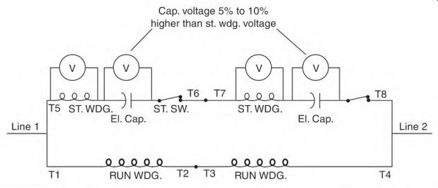
FIGURE 3.39 Schematic for finding the right size capacitors for a dual-voltage
start winding.
If the original capacitor isn't available or readable, use the following data to select a capacitor size that's close enough to start the process:
400 mfd -f hp (a) 120 volts (dual-voltage motors use a 120-volt value)
100 mfd hp at 240 volts
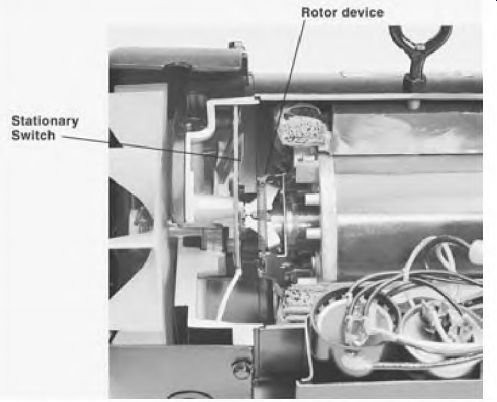
FIGURE 3.40 The start-winding controls. Marathon Electric. Operation of the
Single-Phase Capacitor-Start Motor Rotor device
Switch
The preceding values should not be used to select the actual size capacitor for a motor. Do not allow the start winding to overheat. Electrolytic capacitors must be of the same mfd value when connected in series with each other.
The capacitor-start motor starts the same as a two-phase motor. But, unlike two-phase power, which has two voltages, there is only one voltage applied.
Single-phase power is applied to both the start and run windings to start the motor. About 1 second after power is applied, the rotor should be turning between 75 and 80 percent of synchronous speed. At this time a switch (Fig. 3.40) disconnects the start winding.
The motor now runs on only the run (main) winding. With rated load applied, the rotor pulls the load at or near its nameplate RPM. With no load, the rotor will turn at nearly synchronous RPM. (The load determines the exact speed of the motor.) The capacitor-start and three-phase induction motors both have squirrel cage rotors. To better understand how the rotor gets its power, transformer theory must first be understood.
Transformer Theory
A transformer is a device used to transfer the power of alternating current from one circuit to another without a direct electrical connection. Figure 3.41 is a schematic of a transformer.
Transformer Components
A transformer consists of a primary winding, a secondary winding, and a laminated iron core.
The primary winding is connected to an AC power source. It transforms power to the secondary winding. The secondary winding is on the load side of the device. The laminated iron carries the magnetic flux of the primary winding to the secondary winding.
Voltage applied to the primary winding creates a continually changing current in its circuit. The changing current creates a magnetic field in the iron core, which is changing at the same rate. The laminated core's magnetic flux cuts the conductors of the secondary winding, transforming a voltage into it. The only connection between the two windings is the magnetic link provided by the laminated iron.
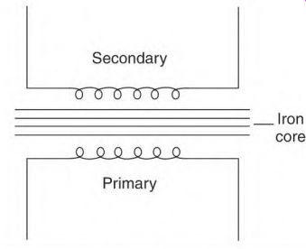
FIGURE 3.41 The schematic of a transformer.
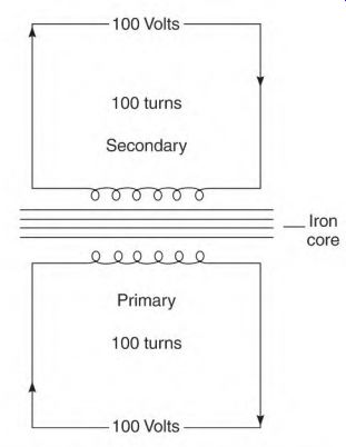
FIGURE 3.42 The volts per turn in the primary determine the volts per turn
in the secondary.
Transformer Function
Assuming there are no losses, the same voltage value of each turn of the primary winding is transformed into each turn of the secondary winding. In the design of most transformers, 5 to 8 percent more turns are added to the secondary winding to account for any losses.
Volts Per Turn
The primary coil (Fig. 3.42) has 100 turns with 100 volts applied to it: 100 volts -r 100 turns of the primary coil = 1 volt per turn in the primary coil.
Each turn of the secondary coil will have 1 volt transformed into it. The voltage value of each turn in the secondary is added to the next turn because they are wound in the same direction. If there are 100 turns in the secondary coil, its voltage output is 100 volts; 10 turns = 10 volts, 1 turn = 1 volt, 200 turns = 200 volts, and so on.
Transformer Rating
Power for the load is furnished by the primary winding when a load is applied to the secondary winding. Although the voltage and amperes of the primary and secondary may vary, the watts-assuming there are no losses- are the same in both windings. The watt load of the primal is determined by the load applied to the secondary.
The physical size (amount of iron and wire size) of a transformer is determined by its power rating. Transformers and motors are similar in this respect. In the United States, transformers are rated in VA or KVA (volts x amps or volts x amps -f 1000) and electric motors are rated in horsepower.
In Europe, both transformers and electric motors are rated in voltamperes or kilo-voltamperes (VA or KVA). For example (with no losses): Primary load is 1000 watts @ 100 volts Secondary load is 1000 watts @ 10 volts Primary winding: 1000 watts 100 volts = 10 amperes in the primary winding Secondary winding: 1000 watts / 10 volts = 100 amperes in the secondary winding
Transformers are designed to step the voltage up or down, or to isolate the power, with no change in voltage value. Hertz is not changed by a transformer.
Solder Gun Transformer
A solder gun makes a good model for transformer theory. The power values and problems are similar to those of the squirrel cage rotor of an induction motor.
Figure 3.43 shows a solder gun and its components, a primary winding, a secondary winding, and laminated iron (which forms a magnetic link between the two windings). The solder gun data is 120 volts and 300 watts, and has 260 turns in the primary coil and one turn in the secondary one.
The formula for volts per turn is Volts / turns = volts per turn The formulas for watts are Volts x amps = watts
Watts -f amps = volts Watts -r volts = amps
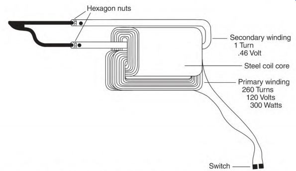
FIGURE 3.43 A solder gun has voltage values that are close to those of a squirrel
cage rotor.
Primary volts per turn and amperes formulas are 120 volts -f 260 turns = 0.46 volt per turn (primary)
300 watts -r 120 volts = 2.5 amperes (primary)
The formulas for secondary volts per turn and amperes are 1 turn = 0.46 volt 300 watts 0.46 volt = 652 amps
0.46 volt -r 652 amps = 0.0007 ohm (resistance of the soldering tip)
The Squirrel Cage Rotor
Components of the squirrel cage rotor are rotor bars, end rings, and laminated iron.
The bars and end rings of the squirrel cage rotor are illustrated in Fig. 3.44. The bars (located in the slots of the rotor iron) are all connected together by end rings. Rotor bars are made in many shapes and sizes, as shown in Fig. 3.45.
End rings join all the rotor bars. The size of the end rings depends on the number of bars covered by the face of one pole. Their size must be slightly larger than the total circular mil area of one-half the bars, covered by the face at points A and B. The center coils of the stator poles (Fig. 3.47) will straddle at least two slots. Current flow in the center coil of the poles is in opposite directions on both sides of the straddled slots. (This creates a pole center like that of a DC shunt field pole.)
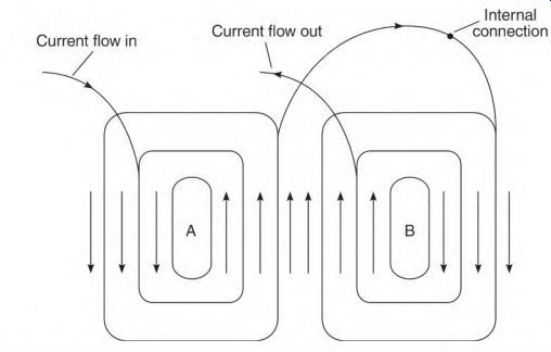
FIGURE 3.46 Two-pole stator coils showing the internal connection.
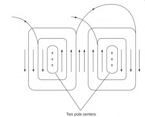
FIGURE 3.47 Electromagnets formed by current flow in the coils of a two-pole
stator.
Current flow in the outer coils of each stator pole is in the same direction. Because the current flows in the same direction, the outer coils may be located in adjacent slots, or they may share the same slot.
All stator coils are well insulated (from the slot iron). The thickness of the insulation is determined by the operating voltage value.
Function of the Squirrel Cage Rotor
The voltage transformed into the bars of the squirrel cage winding from the stator coils is very low. Rotor bars don't have to be insulated from the iron- unlike stator coils-because the voltage transformed into them is so low.
The turn ratio of the stator winding and the squirrel cage winding steps the voltage down to less than 1 volt (similar to the solder gun). Current flow in the rotor bars creates poles that are the same shape as the stator poles (coil groups). Figure 3.48 shows the current flow in the bars of a squirrel cage rotor at loaded speed.
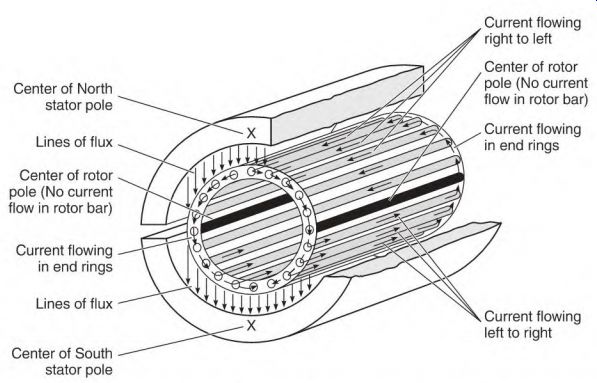
FIGURE 3.48 Current flow in the rotor bars creates poles in the rotor iron.
[Current flowing right to left Center of North stator pole Center of rotor pole (No current flow in rotor bar)
Lines of flux Current flowing in end rings Center of rotor pole (No current flow in rotor bar)
Current flowing in end rings Lines of flux Current flowing left to right Center of South stator pole ]
Stator pole groups are connected so that their polarity is opposite the one next to it. This polarity sequence becomes the same in the rotor. The rotor bars will each have a different amount of power transformed into them. The amount of power is related to the position of the bars in reference to the stator poles.
The bars located at the center (90°) of the stator poles are cut by the most lines of force; therefore, they create the most power. Bars located away from center (90 deg ) create progressively less power. When a bar's angle to the pole face is less than 90 electrical degrees, fewer lines of force cut it. Bars located in the neutral area don't create any power. No lines of force are cutting them at this position. (The iron around the idle bars becomes the rotor's pole centers.)
The opposite polarity stator pole transforms power of the opposite polarity into the bars located within its pole face. Current flows through the end rings from bars of one polarity to bars of the opposite polarity. Two poles form in the rotor iron (which is centered in the neutral area of the stator poles). A repel and attract magnetic force is established between the stator and rotor windings. This magnetic interaction creates torque that pulls the load.
Rotor Hertz and Amperes
The induction motor is very comparable to a transformer. The primary amperes of a transformer are determined by the load applied to the secondary. If the secondary winding were shorted, the primary winding would overheat and be destroyed.
In an induction motor, the rotor bars (secondary winding) are shorted together by end rings. At 0 RPM (locked rotor) the rotating magnetic field of the stator is at synchronous speed. The magnetic lines of force are cutting the rotor bars at maximum Hz (cycles per second). This transforms a very high AC current into the rotor bars. (The stator is furnishing this power, so the amperes are also very high in the stator.) As the rotor accelerates, the difference between the synchronous speed of the stator's rotating magnetic field and the speed of the rotor decreases. Rotor Hz become lower as rotor speed increases. As rotor Hz go down, fewer lines of force cut its rotor bars, resulting in fewer amperes in both the rotor and stator. With rated load applied, the rotor speed will be nameplate RPM, and stator amperes will be at nameplate value. At loaded speed, rotor Hz are about 1.5 to 3 cycles per second. The amperes are high enough in the rotor winding (at this RPM) to produce the motor's rated torque.
Slip, Hertz, and Motor Speed
The difference between synchronous speed and nameplate speed is called slip. Slip produces a calculated number of amperes, torque, and horsepower that equal the motor's rating. A motor rated continuous duty won't overheat at rated RPM. The following calculations start with the basics and explain the relationship of poles, power supply Hz, synchronous speed, slip, and rotor Hz: One pole = 180 electrical degrees.
Two poles = 360° (the number of degrees in one cycle). One Hz of power is produced when a magnet passes one pair of poles in 1 second. Sixty Hz = 60 pairs of poles passed in 1 second.
Hz x 60 seconds = pairs of poles passed in 1 minute.
60 Hz x 60 seconds = 3600 pairs of poles passed in 1 minute.
3600 -4- number of pairs of poles = synchronous RPM (a) 60 Hz.
3600 x 2 = 7200 (the total number of poles passed in one minute). 7200 4- number of poles = synchronous RPM (a) 60 Hz.
7200 4- synchronous RPM = number of poles in a 60-Hz motor.
Any Hz x 60 seconds (to get cycles per minute) x 2 = numerator.
Numerator 4- poles = synchronous RPM. Numerator 4- synchronous RPM = poles.
Slip = the difference between synchronous speed and loaded speed.
1800 - 1750 (nameplate RPM) = 50 RPM of slip.
50 ^ 1800 x 100 = 2.7% slip.
Hz x % of slip = rotor Hz.
60 x 2.7% = 1.66 rotor Hz.
Synchronous speed zero torque
Synchronous speed of a four-pole motor on 60 Hz is 1800 RPM. High-slip rotors have 5 percent slip or 3 rotor Hz. Synchronous motors have no slip.
Their poles will be misaligned a few degrees (behind the stator poles). The amount of misalignment is determined by the load and the strength of the rotating field.
When there is no load, a squirrel cage rotor will accelerate to near- synchronous speed. The rotor Hz are 0, with no torque at synchronous speed. Figure 3.49 illustrates why.
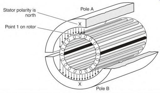
FIGURE 3.49 No torque is produced by the rotor windings at synchronous speed
because no lines of force are cutting the rotor bars.
Stator pole A (in Fig. 3.49) is north and point 1 on the rotor is aligned with it. By the time point 1 of the rotor aligns with pole B of the stator, the polarity of pole B has changed to north. (This compares to the rotor being stationary in a DC magnetic field.)
At synchronous speed, no lines of force cut the rotor bars and no power is transformed into them. When no current flows in the rotor bars, there is no torque.
If the rotor was to somehow accelerate faster than synchronous speed, it would generate power instead of producing torque. The rotor iron is magnetized, and its flux cuts the stator coils, producing power.
Rotor Bar Stress
The squirrel cage winding of the rotor has a wide range of amperes. Rotor amperes are very high every time the motor starts. This causes the rotor bars to get hot. The expansion rate of the rotor bars is much greater than that of the iron. The resulting stress can break the rotor bars.
There are many magnetic polarity changes in the rotor iron from the time a motor starts until it reaches loaded speed. This creates constant vibration in the rotor bars. As a rotor bar crosses each stator slot and aligns with the iron of the next stator tooth, there's a different magnetic pull.
Rotor bars are skewed to reduce the slot- and tooth-caused vibration.
They will crack or break if they aren't tight in the slot.
Cast aluminum squirrel cage windings are used in most standard induction motors. Casting the aluminum rotor bars and end rings results in a tight fit.
This reduces the chance of bars getting loose and cracking from vibration.
Aluminum bars and end rings must be grossly oversized to prevent the normally high starting current from melting them. Oversized bars reduce the amount of magnetic path of the rotor. This is why rotors with cast aluminum windings are larger than rotors with windings made of copper or other alloys.
Broken Rotor Bars
Broken rotor bars decrease a motor's power. Current flowing in each bar contributes to the motor's torque. The current flow is all but stopped when a bar is cracked or broken. The cracked bar is embedded in iron, but because the voltage is so low, very little current is carried by the iron.
The tip of a solder gun is a good example of low voltage and high current.
When the solder gun has had a lot of use, the tip doesn't get hot when the gun is turned on. Even if the nuts holding the tip seem very tight, tightening them slightly makes it work as it should. (Very low resistance virtually stops current flow when voltage is this low.) The number of broken rotor bars and the load determine whether or not the motor fails. The motor's amperes are much lower than normal (with no load). (Amperes in the stator winding depend on the power demand of the rotor winding.) A maximum-loaded motor with broken rotor bars will soon fail. The stator windings will look charred-as though they failed-from being overloaded.
Cracked End Rings
Cracked end rings cause uneven torque and decrease the motor's power, resulting in failure. The failed winding-as with open rotor bars-will be charred as though the motor failed from being overloaded.
The size of the end rings is determined by the number of rotor bars a stator pole covers. End rings must be larger than the circular mil area of half of the rotor bars that are covered by the pole.
Aluminum end rings sometimes have a bubble or piece of slag embedded in them. Any type of flaw will reduce the circular mil area at this point. A reduction in circular mils restricts current flow and the spot gets hot.
High starting current will melt the aluminum at this spot, opening the end ring. When an open aligns with a neutral spot (between the stator poles), the entire rotor current is forced to flow, as shown in Fig. 3.50. The current then doubles in the part of the ring located in the adjacent neutral spot. High current will soon melt the end ring in this area, creating another open.
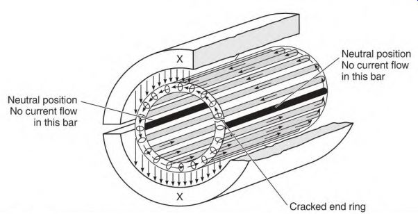
FIGURE 3.50 A cracked end ring stops current to flow when it is a neutral
position. All current has to flow through the opposite neutral location in
the end ring.
[Neutral position No current flow in this bar Cracked end ring Neutral position No current flow in this bar.]
Misaligned Rotor Iron
When the rotor iron is misaligned with the stator iron, the size of the motor's magnetic path is decreased. The result is loss of torque and increased magnetizing amperes. The increased magnetizing amperes overheat the motor (even with no load). Like a motor with broken rotor bars, a fully loaded motor soon fails. The windings will look charred-as with a motor that has failed from an overload.
Other than noticing high no-load amperes, the only way to identify this problem is to view it. It may be necessary to remove one end frame to see the misalignment.
Section 3 Review
1. Unlike the DC generator, which has a commutator and brushes, AC power is taken directly from the stator winding of the AC alternator (05). T F
2. The stator of a single-phase alternator has one winding (or phase) (05). T F
3. The changing position of the exciter magnet (as it sweeps by poles of an alternator's stator) produces the voltage variation of a cycle (07). T F
4. Frequency of power is expressed in cycles per minute (07). T F
5. Electrical degrees are used to reference both time (during a cycle) and the location (on a pole) because electric machines have a circular shape (09). T F
6. A single-phase alternator has one phase; a single-phase motor has a start phase and run phase (in). T F
7. Electrical degrees and mechanical degrees are the same in a two-pole motor (ill). T F
8. The three windings of a three-phase motor are from each other (11).
9. Two phases (start phase and run phase) are symmetrically offset when they are located 90° from each other. T F
10. The most efficient torque is produced when the current flow in two windings is offset (degrees in time) the same as the windings are offset (degrees in location) (13). T F
11. The Hz value of an AC induction motor's power supply determines its approximate RPM (114-115). T F
12. Current flow can be out of step (in time) with voltage (lie). T F
13. Inductive reactance is a form of resistance (17). T F
14. Reactive power always describes the current lagging the voltage (17). T F
15. All current-carrying conductors have a magnetic field around them (17). T F
16. The power of a magnetic field when current increases (17).
a. increases
b. decreases
17. A bucking action between magnetic fields of two AC current-carrying conductors creates resistance to (17)
a. voltage.
b. current flow.
18. The bucking action (described in #\7) as Hz increase (17).
a. increases
b. decreases
19. The resistance (caused by inductive reactance) increases with the length of a wire (in a straight line) (17). T F
20. Impedance is the total resistance of an inductive circuit (18). T F
21. Power suppliers charge for only the true amperes of a circuit (18). T F
22. A wattmeter can be used to find true amperes of an inductive circuit (18). T F
23. An ammeter can be used to find true amperes of an inductive circuit (18). T F
24. The power factor that is given on the nameplate of a motor is an accurate value for all conditions (21). T F
25. Two problems associated with low power factor are voltage drop and an added penalty cost on the power bill (19). T F
26. A motor designed for 50 Hz will have the same horsepower as 60 Hz if the voltage is decreased proportionately (22). T F
27. The motor described in "Impedance in a Three-Phase Winding" can be tested using 230 volts DC (122-123). T F
28. A capacitor will cause the current to (24)
a. lead the voltage.
b. lag the voltage.
29. Oil-filled capacitors lower the two-value capacitor motor's amperes, also lowering the power bill proportionately (26). T F
30. An oil-filled capacitor can be in the circuit (26)
a. 1 second.
b. 1/2 hour.
c. continuously.
31. The electrolytic capacitor can be in the circuit (28)
a. 1 second.
b. 72 hour.
c. continuously.
32. The capacitor-start motor starts on two-phase current and operates on single-phase voltage (129-130). T F
33. Multiple capacitors in parallel can be used to replace a single capacitor as long as the total mfd is the same (32). T F
34. Why must capacitors that are connected in series have the same mfd rating (132-133)?
35. An ohmmeter can be used to find a capacitor's mfd rating (34). T F
36. An ohmmeter is used to determine if a capacitor (34)
a. is open.
b. is shorted.
c. has capacitance.
d. all of the above.
37. An electrolytic capacitor never becomes weak (34). T F
38. The line voltage test can destroy a capacitor, but finds flaws that some electronic instruments miss (34). T F
39. A motor's capacitor is selected according to horsepower rating alone (37). T F
40. The start winding of a capacitor-start motor is in the circuit (36)
a. less than 2 seconds.
b. 5 seconds.
c. continuously.
41. The capacitor-start motor will run at exactly nameplate RPM from no load to full load (137-138). T F
42. The primary winding of a single-phase transformer is (38)
a. connected to the secondary.
b. linked to the secondary by magnetic lines of force.
c. the load side of the device.
43. The amperes of the primary are determined by the load applied to the secondary (139-140). T F
44. A solder gun transformer and the squirrel cage winding of a rotor have similar voltage and ampere values (40). T F
45. The squirrel cage winding forms poles similar to stator poles (44). T F
46. Power in the squirrel cage winding (45)
a. comes directly from the line.
b. flows through the shaft to the bars.
c. is transformed from the stator windings.
47. When the rotor is locked, the rotor Hz is the same as the stator Hz (45). T F
48. Amperes go down as rotor speed increases (45). T F
49. The load determines the speed of the squirrel cage induction motor (45). T F
50. The squirrel cage winding produces no torque at synchronous speed (146-147). T F
51. Broken rotor bars decrease a motor's power (48). T F
52. Why is current nearly eliminated in a cracked rotor bar (48)?
53. A motor that fails from broken rotor bars and/or cracked end rings will look like a motor that had failed from being overloaded (48). T F
54. Misaligned rotor iron will lower the motor's amperes (49). T F