AMAZON multi-meters discounts AMAZON oscilloscope discounts
Shaded-Pole Motor
Multispeed Shaded-Pole Motor
Some shaded-pole motor windings have multiple taps, giving them multiple speeds (Fig. 4.1). Lower speed selections are accomplished by adding more turns or coils between line 1 and line 2. (This lowers the amperes and weakens the torque.) The rotor's high-slip design allows the load to establish a lower speed without overheating. With no load, the motor will accelerate to near synchronous speed on all speed selections.
It is very important to connect the common lead to one side of the line (Fig. 4.1). If high and low leads are connected across the line, the windings between them will burn instantly.
Troubleshooting the Shaded-Pole Motor
The shaded-pole motor will develop worn bearings after years of use. The bearings are usually made of porous bronze that is surrounded with an oil- impregnated wicking. Oil seeping through the porous bronze lubricates the bearings. When the porous bronze becomes plugged, the bearings seize and stall the motor. In some cases, thin oil (such as WD-40) will free the bearings.
The motor may run in this condition until a replacement is found. When the motor is mounted vertically or at an angle, the lower bearing fails first.
Some shaded-pole motors have a thermal cutout bulb embedded in the stator slot, next to a coil. If there is no response when the motor is energized, the thermal unit could be open and unable to reset itself. Bypass the thermal bulb by soldering its leads together. (The motor should operate satisfactorily without it.)

FIGURE 4.1 Schematic of the internal connections in a three-speed shaded-
pole motor.
Split-Phase Motor
Split-phase motors are used in applications such as belt-driven furnace fans and appliances like washers and dryers. This motor has moderate to good torque. They range in size from fractional to 1 hp.
Components of the Split-Phase Motor
The main components of the split-phase motor are a stator, a start-winding switch assembly, and a rotor.
The stator has two windings, the run winding and the start winding (Fig 4.2). The start winding will have some type of device (switch assembly) that shuts it off after the motor starts.
The start-winding switch assembly in Fig. 4.3 has two components, a stationary switch mounted in the end frame and a centrifugal device ...

FIGURE 4.2 Schematic of a split-phase motor.
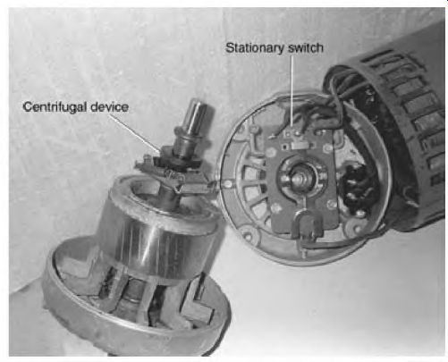
FIGURE 4.3 The stationary switch and centrifugal device of a split-phase motor.
... mounted on the shaft of the rotor. The stationary switch has a set of contacts that controls the start winding.
The centrifugal device holds these contacts closed when the motor is at rest.
The rotor has a low-slip design like most capacitor-start and three-phase induction motors. The squirrel cage windings are usually made of cast aluminum.
Operation of the Split-Phase Motor
Both windings are energized when the motor starts. The start winding is made with small wire. The split-phase motor is sometimes called a resistance start motor. Because of its small wire size (high-resistance winding), the start-winding coils reach peak magnetism about 1/480 second before the run winding does. This is between 40 and 50° separation instead of the ideal 90° (1/240 second) separation the capacitor-start motor has.
When the split-phase motor starts, the weights on the centrifugal device pull the plastic spool away from the stationary switch contacts and shut off the start winding. The start winding is shut off at 75 to 80 percent of synchronous speed. The run winding brings the load up to nameplate RPM or above. Other start-winding control methods are discussed later in the section, under "Electronic Start Switch" and "Time-Delay Electronic Start Switch."
Troubleshooting the Split-Phase Motor
The split-phase motor components (except for the capacitor) are similar to those of the capacitor-start motor. Troubleshooting methods for the capacitor- start motor (described later) can be used on the split-phase motor. Split-phase motors are replaced rather than repaired when there is a problem.
Capacitor Motors
The types of capacitor motors are:
• Capacitor-run
• Capacitor-start
• Two-value capacitor motor (capacitor-start, capacitor-run motor)
The Capacitor-Run Motor
Capacitor-run motors are used when high starting torque isn't required. They are quite trouble free because of their simple design. The high-slip squirrel cage rotor is its only moving part.
The high-slip rotor is designed for high inertia loading. An example of a high inertia load is the heavy squirrel cage fan in some furnaces. The fan is mounted directly on the shaft of the capacitor-run motor. The time involved in bringing the fan up to speed isn't a problem for the capacitor-run motor.
This same type of load would seriously overheat the start winding of a split-phase motor.
Components of the Capacitor-Run Motor
The components of a capacitor-run motor are a high-slip squirrel cage rotor, an oil-filled capacitor, and a stator (with a start winding and run winding). Both start and run windings are high impedance windings, so they can start a high inertia load without overheating.
Operation of the Capacitor-Run Motor
When single-phase voltage is applied, the start and run winding are both energized. Because of the oil-filled capacitor, current flow peaks in the start winding before it peaks in the run winding, creating a rotating magnetic field. (The start and run windings are energized all the time.) These windings draw a small amount of starting current compared to a split-phase or capacitor-start motor. The start-winding current is limited by the oil-filled capacitor.
Although this motor normally runs hot, the electrical components are relatively trouble free. Its weakest components are the bearings. To be competitively manufactured, most of these motors have undersized sleeve bearings and a thin steel frame. If they are equipped with ball bearings, they tolerate angle positions better. Because of this motor's low cost, they are replaced rather than repaired.
Multispeed Capacitor-Run Motor
Some capacitor-run motors have multiple taps, giving them multiple speeds.
Lower speed selections are accomplished by adding more turns or coils between the end of the high-speed winding and line 2 (Fig. 4.4). Extra turns lower the amperes and weaken the motor's torque. The rotor's high-slip design allows the load to lower the motor's speed without overheating it.
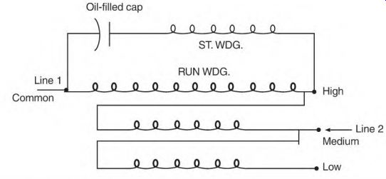
FIGURE 4.4 Schematic of a multispeed capacitor-run motor.
Without a load, the motor accelerates to near synchronous speed on all speed selections.
It is very important to connect the common lead to line 1 as shown in Fig. 4.4. Connecting leads high and low across the line would instantly burn the windings.

FIGURE 4.5 Schematic of a reversible capacitor-run motor.
Reversible Capacitor-Run Motor
Reversible capacitor-run motors are used on low-torque loads such as house fans or dishwashers. Its schematic is shown in Fig. 4.5. Both start and run windings have the same winding data. An external switch places the oil-filled capacitor in series with one winding or the other. The winding in series with the capacitor becomes the start winding.
Troubleshooting the Capacitor-Run Motor
The most common problem with this motor is bearing failure. Some are equipped with porous bronze bearings that depend on oil seeping through the bronze for lubrication. When the porous bronze becomes plugged, the bearing will seize and stall the motor. In some cases, applying thin oil like WD-40 to the bearing keeps the motor running until a replacement is found. When the motor is mounted vertically or at an angle, the lower bearing will fail first.
Winding failures involve the following:
• Burned start or run winding
• Open start or run winding
• Shorted start-winding or run-winding coil
A burned start winding is sometimes caused by a shorted oil-filled capacitor. The start-winding current is no longer limited by the capacitor, so it becomes extremely hot. A burned run winding can be the result of start- winding failure, bearing failure, or an overload. The motor must be replaced if the start or run windings are burned.
An open start or run winding may result from a breakdown in the insulation that separates them. Opens can also be caused by a breakdown in the slot insulation, shorting the winding to the stator core. A motor with this problem must be replaced.
Open lead-to-coil or coil-to-coil connections are less serious. This type of open can be located with an ohmmeter and a sharp needle probe. Fasten one test lead to a motor lead and test each connection by piercing the magnet wire. The open connection can be cleaned and soldered.
A number of things can cause a shorted start-winding or run-winding coil.
Among them are contaminants, voltage spikes, damaged wire insulation, and overload. All of the shorted winding conditions require that the motor be replaced. The cause of the short should be remedied if it could affect the replacement motor.
Oil-filled capacitors will be either shorted or open when they fail.
An analog ohmmeter can be used to detect a shorted or open capacitor fault. If the capacitor is normal, the meter will peg toward low resistance and then slowly drop back and read the leakage value. If the capacitor is shorted, the ohmmeter will show no resistance. An open capacitor will show no reading or a steady, very low reading.
The Capacitor-Start Motor
The capacitor-start motor has good starting torque. It has a wide range of applications. Its size ranges from fractional to 35 hp.
Components of the Capacitor-Start Motor
The main components of the capacitor-start motor are a stator (with a start winding and run winding), a low-slip rotor, a start-winding switch assembly, and an electrolytic capacitor (Fig. 4.6). Operation of the Capacitor-Start Motor Single-phase voltage is applied to both start and run windings. An electrolytic capacitor in the start-winding circuit creates a leading current flow. The start- winding current leads the run winding current by 90° (or 1/240 second). The result is a very efficient rotating magnetic field and high starting torque.
When the rotor reaches 75 to 80 percent of synchronous speed, its centrifugal device releases the stationary switch contacts and disconnects the start winding. The rotor accelerates the load to nameplate RPM or above.
Troubleshooting the Capacitor-Start Motor
Following are the most frequent component breakdowns of the capacitor- start motor, in descending order:
• Start switch assembly (stationary switch and centrifugal device)
• Electrolytic capacitor
• Start winding
• Run winding
• Bearings
• Rotor

FIGURE 4.6 Schematic of a capacitor-start motor.
Start Switch Assembly
The start switch assembly is responsible for connecting and disconnecting the start winding. The stationary switch contacts arc, vaporizing some of their material each time the motor starts.
Over time, the contact area will no longer be large enough to make a good connection (resulting in dead spots, as described next). With the contact area reduced, high starting current can melt the contacts, fusing them together (the start winding will then stay energized). The motor will be noisy and won't get up to full RPM. If the high-current protection device doesn't function, the start winding and capacitors overheat and fail.
Dead Spots
Worn contacts, centrifugal device spool, or thrust washers can cause the motor to have dead spots. It won't start unless the shaft is moved slightly. Moving the shaft changes the spool pressure point against the stationary switch, the contacts close, and the motor starts.
To verify that the switch is the component that is intermittently faulty, disconnect T5 and T8. Connect an ohmmeter across these leads and turn the shaft. If no open circuit occurs, pull the shaft away from the switch end of the motor and, at the same time, turn the shaft. (The stationary switch is normally located on the end opposite the shaft.)
Magnetic Center and Thrust Washers
Excessive shaft end play can cause intermittent starting problems. The rotor will try to seek its magnetic center.
(The thrust washers should keep the rotor at this alignment.) If the rotor is not at magnetic center, the motor loses power and the magnetizing amperes are increased. This was discussed in Section 3 under "Misaligned Rotor Iron."
If the start contacts aren't closed when the rotor is aligned properly, the switch assembly should be adjusted accordingly.
Centrifugal Device Problems
If the preceding tests don't reveal an open circuit in the start winding, the problem may be in the rotating device or the capacitor (if it is in the capacitor, see "Open Capacitor" a bit later in the section). If the centrifugal device is dirty or worn, it can cause intermittent start problems. Cleaning or replacing it requires disassembling the motor or taking it to a repair center. When the centrifugal device is replaced, it must be positioned in exactly the same place as the old one.
The decision to replace the start switch assembly components depends on the overall condition of the motor and the repair cost. An electronic start switch maybe the best option. Operation of the electronic start switch is explained later in the section under "Alternative Start-Winding Switches." The motor's original stationary switch contacts and centrifugal device can be replaced with start switch devices, also described later under "Alternative Start-Winding Switches."

FIGURE 4.7 Current flow when the capacitor discharges into the motor circuit.
Normal Braking Effect Caused by the Electrolytic Capacitor
It's normal for a brief braking action to take place as a capacitor-start motor coasts to a stop. As the motor slows, the centrifugal device closes the start contacts.
The capacitor will now discharge into the closed circuit of the start and run windings. The power coming from the capacitor is DC (Fig. 4.7). (When direct current flows in the stator windings of an induction motor, there is a strong braking effect on the rotor.)
Some three-phase motor controls use DC braking to slow a coasting type load. DC power can't, however, hold the motor's shaft stationary.
Electrolytic Capacitor
The following problems can occur with an electrolytic capacitor:
• Shorted
• Open
• Weak capacitor (loss of capacitance)
Shorted Capacitor
A motor with a shorted capacitor has very little starting torque. The peak magnetism time of its two windings is too close together (see "Operation of the Capacitor-Start Motor" earlier). An ohmmeter can be used to test the capacitor, but (because of possible internal parallel circuits) it's necessary to disconnect one of the capacitor leads.
Short the capacitor terminals together and discharge it before using the ohmmeter. Meters are available that can measure the capacitance of capacitors.
A normal capacitor will make an analog ohmmeter needle peg as if there is a short; then it will drop back slowly and read the capacitor's normal leakage. If the capacitor is shorted, the needle remains at the pegged position.
Open Capacitor
If a motor has only one capacitor, the start winding is disconnected when the capacitor is open and the motor won't start.
The capacitor can be tested for an open with an ohmmeter or a test light. One location in a capacitor where opens occur is under the lid. The connection straps for the plates are riveted to the terminals under the lid.
These straps flex when the capacitor heats and cools, causing them to crack and break at the rivet. (The lid's retaining ring can be pried out to check this problem.) An open capacitor is sometimes an intermittent problem. The problem can be mistaken for dead spots caused by faulty start contacts.
When the stationary switch is replaced because of faulty contacts, the capacitor should be checked for cracked or broken straps.
Some centrifugal devices don't put even pressure on the stationary switch's wear pads. The contacts open and close (flutter) when the rotor approaches disconnect speed. Contact flutter will decrease contact life.
It also produces voltage spikes in the start winding that will destroy the capacitor. Excessive contact flutter can cause frequent capacitor breakdown.
Weak Capacitor
Overheating is the main cause of a capacitor becoming weak. A capacitor is overheated if there are too many starts per hour or if the capacitor is mounted in direct contact with the motor shell. A weak capacitor reduces the motor's starting torque.
Overheating dries out some of the capacitor's electrolyte fluid. Loss of electrolyte fluid decreases the amperes available to the start winding and lowers the motor's torque. Applying line voltage and using the formula explained under "Capacitor Test Formula" in Section 3 will determine if the capacitor is weak.
If the motor doesn't have good starting torque, its capacitor may have been replaced with one that is too small. In this case use the method explained in Section 3 under "Determining the Right Size Capacitor." Start Winding All four of the following problems require that the motor be rewound or replaced:
• Burned
• Open
• Shorted coils
• Shorted to the run winding
Burned Start Winding
The start winding will overheat if it is energized for more than 3 seconds. An overload or a faulty start switch that doesn't allow the start contacts to open is frequently the cause of burned start windings.
(Burned windings can be seen and/or smelled.) A motor with burned or discolored start coils must be rewound or replaced.
Open Start Winding
An open in the start winding can occur if it is shorted to the run winding. Because of the start winding's smaller wire size, it will melt in two. Most motor manufacturers don't put insulation between the start and run windings the way electric motor repair centers do. Rewound motors are less prone to start winding to run winding shorts.
It's common for opens to occur in motors wound with aluminum magnet wire. If the environment is corrosive (for example, a washing machine), a small bare spot in the wire will corrode it in two. Electric motor repair centers never use aluminum wire.
If the start winding is not burned or discolored, the open can be located with a test light or an ohmmeter. For example, a faulty internal lead-to-coil or coil-to-coil connection.
The following procedure should be used: Disassemble the motor and remove the insulation from the lead-to-coil and coil-to-coil connections. Start at one end of the start winding and proceed toward the other end as shown in Fig. 4.8. An open connection can be scraped clean and re-soldered.
Smaller capacitor-start motors with a faulty start winding should be replaced. The larger capacitor-start motors can be economically rebuilt if the cost is near that of a new motor. Service centers use a higher temperature class insulation than is in the original factory-installed winding. Most use class H (Fig. 4.9). Service centers also insulate between the start and run windings.
Shorted Coils-Dual-Voltage Start Winding
Some capacitor-start motors have dual-voltage start windings (Fig. 4.10). The dual-voltage start winding has two pairs of lead wires numbered T5 through T8. Half the start-winding circuit is between numbers T5 and T6, and the other half is between T7 and T8. Capacitor(s) are always located (as shown in Fig. 4.10) between the start winding and T6 and between the start winding and T8. The start switch contacts will be located as shown in Fig. 4.11 or 4.12.
The two circuits have identical data, so they can be comparison tested. It is unlikely that both circuits would have the same problem. A micro-ohmmeter or limited AC current can be used for this test. The current shouldn't be so high that it overheats the start-winding coils.
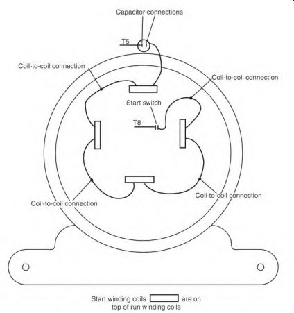
FIGURE 4.8 Locating a faulty connection in the start winding.
Insulation Class Temperature Rating
A - - - - 105 degrees C B 130 degrees C p 155 degrees C H 180 degrees C
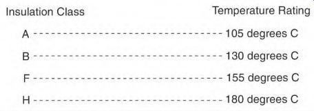
FIGURE 4.9 Temperature chart for insulation classification.

FIGURE 4.10 Dual-voltage start-winding number sequence.
Disconnect the leads T5 through T8. Compare the reading between T5 and T6 to the reading between T7 and T8. (Do not include the capacitors.) It may be necessary to turn the shaft slowly while recording the high and low readings. The results should be identical. If one circuit has lower resistance (with an ohmmeter) or higher amperes (with limited AC), it has shorted coils.

FIGURE 4.11 Dual-voltage start winding (with contacts for each half).
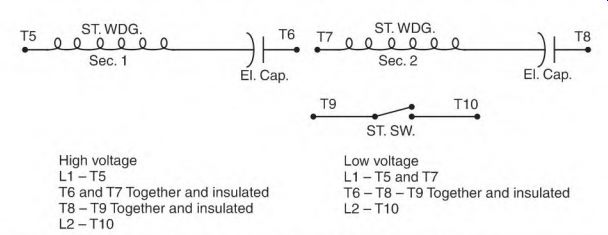
FIGURE 4.12 Dual-voltage start winding with one set of contacts.

FIGURE 4.13 Connecting a dual-voltage start winding using the in-on-the- odds,
out-on-the-evens method.
Each circuit should also be tested to the frame of the stator for an insulation breakdown to ground. A short to ground requires a complete rewind or replacing the motor.
Start Winding Shorted to Run Winding
The start winding and run winding normally aren't internally connected. The only exceptions are motors that have predetermined rotation, such as centrifugal pump motors. If there is continuity between the start and run windings, the motor will have to be rewound or replaced.
Connecting the Dual-Voltage Start Winding
Figure 4.13 shows the start- winding lead number system. To connect a dual-voltage start winding, simply use the following phrase: in on the odds and out on the evens. Start-winding leads are always numbered T5 through T8.
Run Winding
The run winding normally has fewer problems than the rest of the capacitor-start motor's components. Overheating from overload, high ambient temperature, low voltage, and bearing failure cause the following problems:
• Burned coils
• Shorted turns
• Shorted coils (dual voltage)
• Short to the start winding
• Short to the frame
• Open winding (dual voltage)
Burned Coils
Burned coils are always visible. They usually have a burned varnish smell. The motor may even run normally in this condition. It definitely should be replaced or rewound.
Shorted Turns
Shorted turns lower the motor's resistance. (Amperes will increase and cause the windings to overheat.) The stator's magnetic balance becomes upset, making the motor noisy. A ringing or high-pitched sound sometimes indicates shorted turns.
A low power factor can be mistaken for shorted turns. If the no-load amps are 10 to 15 percent higher than nameplate amperes and the motor sounds normal, a low power factor may be the cause. Normally, most single-phase motors have a low power factor. With no load, it's common for fractional horsepower motors to draw higher than their nameplate amperes.
They often draw fewer amperes when fully loaded. The power factor of almost all AC induction motors improves when they are fully loaded.
Shorted Coils, Dual-Voltage Run Winding
Many capacitor-start motors have dual-voltage run windings (Fig. 4.14). The dual-voltage run winding has two pairs of lead wires numbered T1 through T4. Half of the run-winding circuit is between T1 and T2; the other half is between T3 and T4.
The two circuits have identical data, so they can be comparison tested.
It is highly unlikely that both circuits would have identical problems. Use a micro-ohmmeter or limited AC current for this test.

FIGURE 4.14 Testing both circuits of dual-voltage run winding using the schematic.

FIGURE 4.15 Connecting a dual-voltage run winding, using the in-on-the-odds,
out-on-the-evens methods.
Disconnect leads T1 through T4. Compare the readings between T1 and T2 to the readings between T3 and T4. It maybe necessary to turn the shaft slowly while recording the high and low readings. The results should be identical. If one circuit has lower resistance (with an ohmmeter) or higher amperes (with limited current), it has shorted coils.
Each circuit should also be tested for a ground to the frame of the stator.
Both a short and a ground require that the motor be rewound or replaced.
Figure 4.15 shows the numbering system for run-winding leads. (In 1967, NEMA interchanged the numbers T2 and T3 on single-phase motors.) To connect a dual-voltage run winding, just remember the following phrase: in on the odds and out on the evens. Run windings are always numbered T1 through T4.
Run Winding Shorted to Start Winding
Run and start windings normally aren't internally connected. The only exceptions are motors that have predetermined rotation, such as centrifugal pump motors. If there is continuity between the start and run windings, the motor will have to be rewound or replaced.
Run Winding Shorted to the Frame
Disconnect the power. With an ohmmeter, test from all run-winding circuits to a clean spot on the stator frame. If the reading indicates a solid ground, the motor must be rewound or replaced. If the reading is between 2 and 50 megohms, clean and dry the motor. If this doesn't restore the reading to infinity, the motor must be rewound or replaced. The bottom coils are subject to water-related low ohmmeter readings.
Open Run Winding, Dual-Voltage, Low-Voltage Connection
If one circuit of a dual-voltage run winding is open, the motor will lose slightly more than half its power. The motor will start slower than normal unloaded. Depending on its internal connection method, it will either run smoothly or be slightly noisy.
An ohmmeter or test light can he used to identify the open circuit. If the open is in a lead-to-coil or coil-to-coil connection, it can be soldered. If a coil group is open internally, the motor must be rewound or replaced.
Submerged Motor
If a single-phase motor has been submerged in water, but not energized, it may not need rewinding or replacing. Cleaning and baking its windings might be all that's needed. However, the electrolytic capacitor shouldn't be baked in an oven.
The windings should be tested first with an ohmmeter. (A wet winding should never be subjected to a test voltage that could arc through the wet slot insulation.) The baking temperature should not exceed 200 degr. F. The ohmmeter test should read infinity after baking. The windings should be given a coat of air-drying varnish after they have been cleaned, dried, and tested.
When water soaks the slot insulation, a battery action can sometimes be detected. As long as the slot insulation is wet, a small voltage can be read (with a millivoltmeter) between the winding and the frame. A zero reading would indicate that the motor has been baked long enough. If the ohmmeter test now shows infinity, other test instruments such as a megohmmeter or surge tester can be used.
If a motor has been submerged, it should be disassembled, cleaned, and dried as soon as possible. If it has sleeve bearings, the shaft's bearing surface will soon become rust pitted. The sleeve bearing motor should have the oil wick material and oil replaced. (Ball bearings should be replaced.) The capacitor and start switch should be cleaned and wiped dry, but if there was prolonged submersion, the capacitor should be replaced.
(Contaminated water causes the aluminum components inside the capacitor to corrode.) Oil-filled capacitors can be cleaned and wiped dry because they are sealed.
Bearings
A worn sleeve bearing will make sharp clattering or rumbling sounds, especially when the motor starts. Disconnect the belt and move the shaft back and forth in line with the load. There should be no movement.
Small motors are usually replaced because replacing sleeve bearings isn't cost effective.
Ball bearings are very noisy when faulty. They can be replaced, but the repair cost must be compared with the cost of a new motor. The age and condition of the motor is part of this decision.
The stationary switch should also be replaced at this time.
Rotor Cast aluminum rotors are used in most single-phase motors. If they have open rotor bars or end rings, the motors are replaced because it isn't cost effective to repair them.
Loss of torque is a sign of open rotor bars or end rings. The motor won't draw many amperes with no load and will start a load more slowly than normal. Loaded RPM will be lower than the nameplate value. The start and run windings won't show any problems.
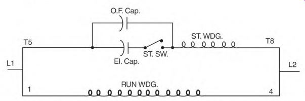
FIGURE 4.16 Schematic of the two-value capacitor motor.
Two-Value Capacitor Motor (Capacitor-Start, Capacitor-Run Motor)
The two-value capacitor motor has the same components as the capacitor- start motor (Fig. 4.16). An oil-filled capacitor is added for power factor improvement. The function of the two-value capacitor motor is discussed in Section 3 under "Oil-Filled Capacitor Connection in a Two-Value Capacitor Single-Phase Motor." Troubleshooting methods for the two-value capacitor motor are the same as those for the capacitor-start motor. They are discussed earlier in the section under "The Capacitor-Start Motor." Following are additional problems and troubleshooting methods for the oil-filled capacitor.
Troubleshooting the Oil-Filled Capacitor
The two major problems for the oil-filled capacitor are open and shorted.
If the oil-filled capacitor becomes open, the full magnetizing amperes of the run winding are carried by the motor's circuit (the circuit's voltage drop will increase). The loss of the oil-filled capacitor won't affect the motor's performance, but it will make more magnetic noise.
If the oil-filled capacitor becomes shorted, the start switch and the electrolytic capacitor(s) are bypassed. The start winding is now connected directly across the line. If the motor is restarted, it draws high current and has very little starting torque. The start winding will be destroyed in a few seconds. Disconnect the shorted oil-filled capacitor, and the motor will operate satisfactorily without it.
Electrolytic Capacitor Connection Rules and Formulas
Capacitors are connected parallel, series, and in combinations of both. The reason for these connections was discussed in Section 3 under "Parallel Electrolytic Capacitor Connection" and "Series Electrolytic Capacitor Connection." Electrolytic capacitor connection rules are as follows:
• Capacitors connected in parallel don't need the same microfarads (mfd) rating.
• Capacitors connected in series must have the same mfd rating.
• There are never more than two capacitors connected in series with each other. Two capacitors in series are normally a high-voltage connection.
The following electrolytic capacitor formulas determine total capacitance value for series and parallel connections and combinations of them:
• Parallel mfd ratings of each capacitor added together = total mfd
• Series mfd rating of one capacitor divided by the number of capacitors in series = total mfd
• Capacitors of unequal mfd rating in series product/sum (example below): cap ^1 mfd x cap #2 mfd -h cap # 1 mfd + cap # 2 mfd = total mfd
In Fig. 4.17 (a) and (b) mfd values are added together for total mfd. In part (c) the mfd value is found by dividing the mfd value of 1 by the total number of them (2).
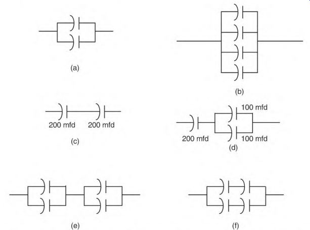
FIGURE 4.17 Six combinations of electrolytic capacitor connections found in
capacitor-start motors.
Connection (d) adds the parallel connected capacitor's mfd values and then divides the result by 2.
Connection (e) shows two capacitors in parallel that are in series with two capacitors in parallel. First find each parallel circuit's value and then divide the result by 2 (the number of circuits). (Each parallel circuit must have the same mfd value.) Connection (f) shows two capacitors in series and in parallel with two capacitors in series. (Capacitors in series must have the same mfd rating.) Divide the value of one capacitor by 2 (the number of them in series) to find the mfd of each circuit. Add the value of each circuit to get the total mfd.
Troubleshooting Electrolytic Capacitors
Figure 4.18 shows how mfd values change when there is a shorted or open capacitor in the connection. The multiplier 11 is explained in Section 3 under "Capacitor Test Formula." The number 11 applies because this is a 240-volt application. The capacitors are all rated 200 mfd and 120 volts. Using the logic of the test formula, the amperes available to the start winding can be calculated. The results explain why a motor reacts as it does when there are shorted or open capacitors.
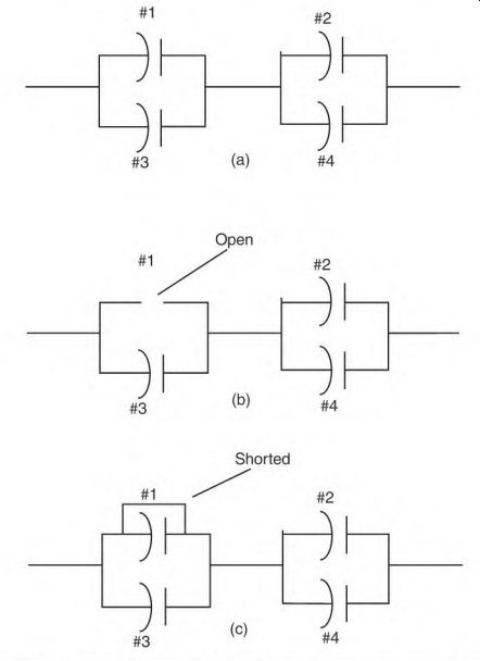
FIGURE 4.18 Mfd values change when a capacitor is open or shorted.
The first problem (Fig. 4.18) has two capacitors in parallel and in series with two capacitors in parallel. The second problem (Fig. 4.19) has two capacitors in series, connected in parallel with two capacitors in series.
Both connections are used in capacitor-start motors rated 5 hp or more.
In Fig. 4.18, the sum of capacitors #1 and #3 (400 mfd) is the same as the sum of capacitors #2 and #4 (400 mfd): 400 -r 2 = 200 mfd. The power is 60 Hz at 240 volts, making the multiplier 11. 200 mfd h- 11 = 18 amperes available to the start winding when there are no faulty capacitors.
In Fig. 4.18 (b), capacitor #1 is open. Capacitor #3 (200 mfd) is in series with capacitors #2 and #4 (400 mfd). [200 mfd x 400 mfd] -r [200 mfd + 400 mfd] = 133 mfd, and 133 mfd -r 11 = 12 amps available to the start winding.
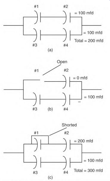
FIGURE 4.19 Mfd values change when one capacitor is open or shorted.
(Starting efficiency is decreased because of the loss of mfd.) The time will decrease between the peak magnetism (phase angle) of the start and run windings. The loss of one-third of the amperes available to the start winding reduces the motor's starting power. The motor won't start a maximum load.
In Fig. 4.18 (c), capacitor #1 is shorted. Capacitor #2 is now in parallel with capacitors #2 and #4. The total capacitance is now 300 mfd.
The phase angle is well off the ideal 90°, lowering the starting efficiency. Start amperes are higher than normal. The motor may start but wouldn't be able to start a load. Extremely high amperes indicates a shorted winding, when actually the problem is only a shorted capacitor.
Motor performance problems that are shown in Fig. 4.19 are similar to problems that were found in Fig. 4.18. This connection is two capacitors in series in parallel with two capacitors in series.
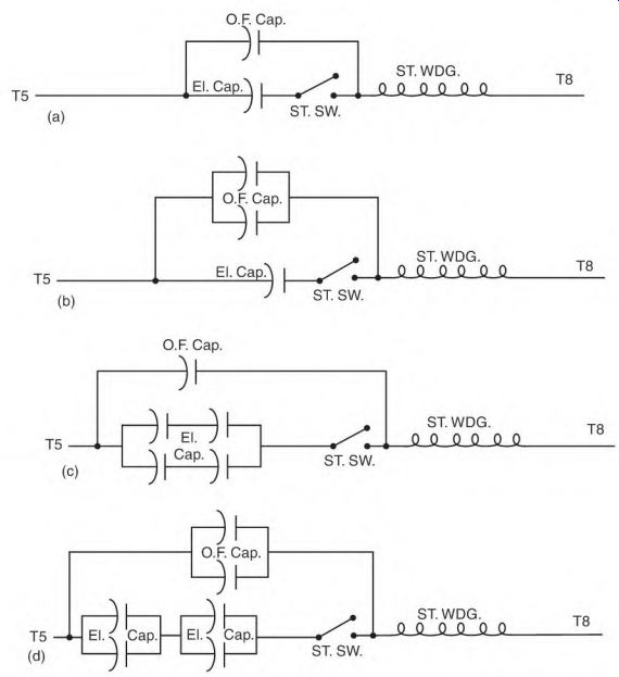
FIGURE 4.20 Several connection combinations found in the two-value capacitor
motor's start winding.

FIGURE 4.21 A separate winding designed for correcting the motor's power factor.
Two-Value Capacitor Motor Connections
Two-value capacitor motors (with electrolytic and oil-filled capacitors) use the connections shown in Fig. 4.20. Oil-filled capacitors are always connected in parallel with the electrolytic capacitor and the start switch contacts. If more than one oil-filled capacitor is used, they are always connected in parallel with each other. The voltage rating of the oil-filled capacitor will be two or more times the applied voltage value. Both types of capacitors are found mounted in the motor, on the motor, or remote from the motor.
Power Factor Correcting Winding
Figure 4.21 shows a schematic of a special winding in series with an oil-filled capacitor. This winding is wound on top of the start winding and connected so their polarities are the same. Its purpose is to correct the power factor of the motor.
High-Voltage Problems of the Two-Value Capacitor Motor
If the two-value capacitor motor is connected to a coasting load (such as a radial arm saw), voltage as high as 1500 volts is generated in the motor's circuitry. (A magnetic interaction between the rotor cage, the closed circuit of the start and run windings, and the oil-filled capacitor creates the high voltage.) The power value of the high voltage is very low, but it can destroy or damage electronic components or anything connected in the motor's circuitry.
Capacitor-Start Motor Connections
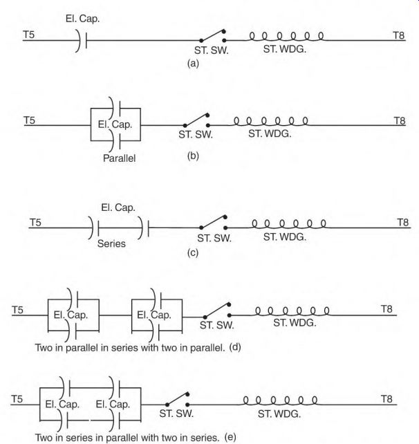
FIGURE 4.22 Start winding connections found in capacitor-start motors, (a)
One voltage: This start winding connection can be used on low or high voltage,
but not both. The voltage rating of the capacitor determines the voltage applied,
(b) One voltage: This start winding connection can be used on low or high voltage,
but not both. The voltage rating of the capacitor determines the voltage applied,
(c) High voltage only: Capacitors will be rated low voltage only, (d) High
voltage only: Capacitors will be rated low voltage only, (e) High voltage only:
Capacitors will he rated low voltage only.
Figure 4.22 (a through e) covers most capacitor-start motor connections.
There is no standard order of sequence for the components. Regardless of the sequence, the start switch contacts must shut off the electrolytic capacitor(s) and the start winding. Figures 4.22 (a) and (b) can be used on high-voltage, low-voltage, or dual-voltage applications. The capacitor's voltage rating must be the same as the applied voltage when the application is a single voltage.
Dual-voltage applications require lower-voltage capacitors. The run winding is used as an autotransformer to keep the voltage applied to the start winding low. Figure 4.23 shows the voltage value when the dual-voltage run winding is connected for high voltage. When the start winding is connected across one-half of the run winding, it will receive only half of the applied voltage.
The series connections in Figs. 4.22 (c) through (e) are all high-voltage applications. The capacitors are all rated low voltage. Figures 4.22 (d) and (e) are connections used on larger-horsepower motors.

FIGURE 4.23 Schematic showing the voltage across the run-winding coils and
leads when the motor is connected for high voltage.
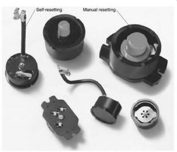
FIGURE 4.24 Self-resetting and manual resetting thermal devices.
Thermal Protective Devices
Thermal protective devices are used to protect a motor from burnout caused by overload and failure to start. There are two types, manual resetting and self-resetting. Both types have a bimetal component that bends in a predetermined direction when overheated from excessive current (Fig. 4.24).
Manual resetting thermal devices must cool before they can be reset.
(Larger thermal devices may take 10 to 15 minutes to cool sufficiently.) There is a definite snap when they reset. They should be in a convenient location. If they are mounted in a motor's connection box, they can be relocated.
A self-resetting thermal device will reset itself and start the motor when it cools. Machinery that can cause injury shouldn't have motors with self- resetting protective devices.
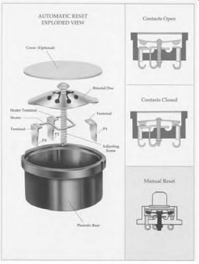
FIGURE 4.25 The internal connection of a thermal device.
Components of the Bimetal Thermal Protective Devices (for Single-Phase Motors)
This type of protective device has a disc and two sets of contacts. Two of the contacts are mounted on the movable part of the disc. The two mating contacts are mounted on the stationary part of the device.
Figure 4.25 shows the circuitry of a thermal device. The terminal marked P1 (on the thermal device) is connected to one of the stationary contacts. A lead in the motor's connection box (labeled P1) is connected to this terminal.
If the motor has a connection board, P1 is soldered to a bolt, marked P1. P1 (as a lead or bolt) is always connected to line 1. All of the circuitry of the thermal device and the motor are in series with P1.
The P2 terminal is connected to the stationary contact across the disc from P1. If the motor has a connection box, P2 is a brown wire and may or may not be marked P2. If the motor has a terminal board with connecting bolts, there's also a bolt labeled P2.

FIGURE 4.26 Thermal device for single-voltage motors.
Current through P2 has no effect on the function of the thermal device.
(It disconnects when the device trips off.) If the lead P2 isn't used in the connection, it must be insulated.
A small heat element (located near the disc) is connected between P2 and P3. When there's an overload, higher than normal current flows through the heat element and P3. The heat element gets hot, making the disc bend, disconnecting all motor circuits. (P3 is always connected to a winding that is affected by an overload.)
Connections and Operation of the Thermal Protective Device
Thermal devices are used on all types of motors. Single- and dual-voltage capacitor-start motor connections with thermal devices are discussed here.
Single-Voltage Capacitor-Start Motor
Figure 4.26 shows a thermal device connected to a single-voltage capacitor- start motor. Line 1 is connected to P1. P3 is connected directly to the run winding. A lead marked T1 is connected to P3, making it accessible to combine start-winding leads T5 or T8 with T1. (To reverse the motor, interchange T5 and T8.) T4 and T5 or T8 are connected to L2.
P1 (line 1) is disconnected from all circuits when the thermal device functions because of an overload.

FIGURE 4.27 When connected for high voltage, this motor draws 10 amperes.
The voltage read from the T2 and T3 connection to either line is half of the line voltage.

FIGURE 4.28 Each parallel run-winding circuit draws 10 amperes. The voltage
drop across each coil is the same as with the high-voltage connection.
If the thermal device becomes defective, T1 (with T5 or T8) can be connected directly to line 1. This will bypass the defective thermal device.
(The heat element would melt if T1 were inadvertently connected to line 2 when P1 is connected to line 1.) The start winding is sometimes connected to P2 so that its amperes don't affect the heat element. It could be destroyed at this location if the heat element becomes open.
Dual-Voltage Motor, Connected Low Voltage
The dual-voltage motor's run winding has two circuits. Each circuit contains exactly half of the run winding. This makes it possible to connect the run winding high voltage (series) or low voltage (parallel). Figure 4.27 shows the voltage value across each pole when the winding is connected high voltage (series). Figure 4.28 shows the same voltage value across each pole when the winding is connected low voltage (parallel). When the voltage is the same across each pole, the amperes through each pole are the same (for both connections). Full-load amperes for this motor are 20 amps (low voltage) and 10 amps (high voltage). When connected low voltage (parallel), each circuit draws 10 amps, for a total of 20 amps. When connected high voltage, the run circuit draws 10 amps.
The heat element of the thermal device is connected in series with one circuit of the run winding. Whether connected high or low voltage, the full- load amperes through the heat element will be 10 amps. The trip value for this motor's protective device is based on a 10-amp load.
Figure 4.29 shows a dual-voltage capacitor-start motor connected low voltage. Line 2 is connected to T2, T4, and T5 (or T8). (To reverse this motor, interchange T5 and T8.) Line 1 is connected to P1. T1 (from the run winding) and an external lead labeled T1 are internally connected to terminal P3 of the thermal device.
External lead T1 is sometimes connected to T5 (or T8) and insulated.
Some motor nameplates specify that T5 (or T8) be connected to P2. (The start- winding current won't go through the heat element when connected to P2.) Run-winding lead T3 is connected to P2 and insulated. The current of T3 (10 amps) will bypass the heat element when connected to P2. If the thermal device opens because of an overload, T1 and T5 (or T8) are disconnected from line 1. At the same time, P2 disconnects T3 from line 1. T2, T4, and T5 (or T8) remain connected to line 2.
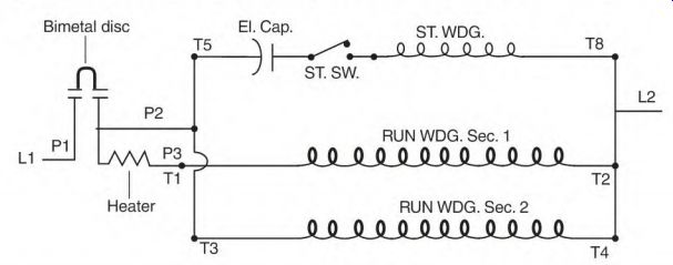
FIGURE 4.29 A dual-voltage motor-and its thermal protection device- connected
for low voltage.
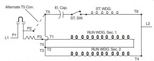
FIGURE 4.30 The same motor and thermal device connected for high voltage.
Dual-Voltage Motor, Connected High Voltage
Figure 4.30 is the same motor as described above, but connected for high voltage. At full load, the run winding draws 10 amperes. Line 1 is connected to P1. P2 isn't used and is insulated, and T2, T3, and T5 (or T8) are joined and insulated. T4 and T5 (or T8) are connected to line 2. (T5 or T8 can also be connected to P2.) This motor can be reversed by interchanging T5 and T8.
Whether this motor is connected high or low voltage, each run winding pole must have 10 amps flowing through it to produce full power.
Limitations of Thermal Protective Devices
Protection that is provided by the thermal device can be reduced by temperature variations. Ambient temperature affects the trip time of all thermal devices. If the ambient temperature is 100 F, the device may not trip soon enough to protect the motor.
Thermal protective devices are mounted either inside the motor or in its connection box.
When the device is mounted inside (Fig. 4.31), the motor's internal temperature is factored into the thermal device's trip temperature. The trip temperature is based on the motor having reached full running temperature.
If the motor is overheated, it may trip off each time the motor tries to start. The cycle will continue until the motor is disconnected long enough for both to cool. If the motor is extremely cold, the thermal device may not trip before the windings are damaged.
Frequent starts can cause excessive tripping with an internally mounted thermal device. High ambient temperature may trip off a lightly loaded motor when it is restarted.
If the thermal device is mounted in the connection box, the motor's internal temperature won't affect it.
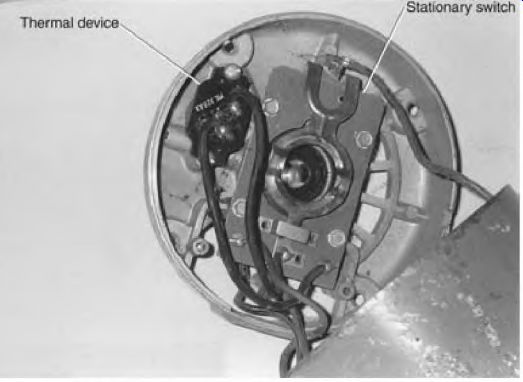
FIGURE 4.31 Thermal device mounted in the motor's end frame. Marathon Electric.
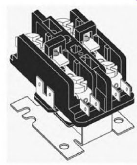
FIGURE 4.32 A potential relay used for the start-winding control. White-Rodgers.
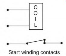
FIGURE 4.33 The potential relay's four connections.
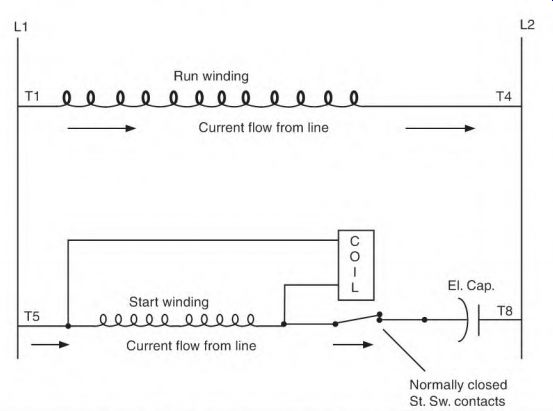
FIGURE 4.34 Schematic of the motor and its potential relay.
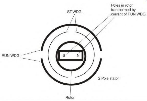
FIGURE 4.35 Poles in the rotor iron align with the start winding.
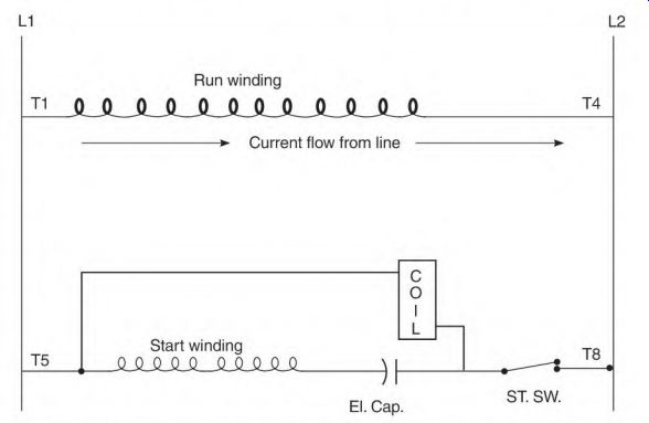
FIGURE 4.36 This connection won't allow the motor to start a load.
Alternative Start-Winding Switches
The stationary switch and centrifugal device assembly can be replaced with numerous types of start-winding controls, which include:
• Potential relay start switch
• Electronic start switch
• Time-delay electronic start switch
• Heat-activated start switch
• Current relay start switch
Potential Relay Start Switch
The potential relay start switch is shown in Fig. 4.32. A motor's original stationary switch contacts and centrifugal device can be replaced with a potential relay. They are available for 115- and 230-volt applications. The same switch can control two-, four-, and six-pole capacitor-start motors.
Potential Relay Components
The potential relay start switch illustration in Fig. 4.33 consists of a coil and a set of horsepower-rated contacts. The coil must match the voltage applied to the motor (115 or 230 volts). A dual-voltage motor requires a coil rated for a 115-volt application.
The relay contacts must be rated as high as or higher than the motor's horsepower. Some large capacitor-start motors have a two-circuit start winding and use a separate relay for each circuit.
Operation of the Potential Relay
Figure 4.34 is a schematic of the motor and its potential relay. The power factor of the start winding is low when the motor is starting. As the rotor accelerates, the voltage/current angle (timing), or power factor, of the start winding improves. As the power factor improves, the voltage transformed from the rotor poles to the start winding increases. At 75 to 80 percent of synchronous speed, the voltage across the start winding is high enough to
Start winding contacts make the relay coil function. The start winding is now disconnected from the line. Power continues to be transformed into the start winding from the rotor, keeping the contacts open until the motor is shut off. (A voltage is transformed into the start-winding coils from the poles of the rotor.) Figure 4.35 shows the alignment of rotor poles.
The voltage value (at 75 to 80 percent of synchronous speed) varies slightly from motor to motor. Spring tension (which holds the contacts closed) can be adjusted to fit a motor's individual requirement. Increasing or decreasing the spring tension is done by bending the spring support.
If the motor's capacitor is connected in the relay coil/start-winding circuit, the power factor is immediately raised, and the relay coil functions too soon (Fig. 4.36). When the contacts open, the rotor speed is so slow that the run winding can't pull the rotor up to speed.
If the motor is extremely overloaded, or if there is a short power interruption, the potential relay reconnects the start winding and brings the rotor back up to disconnect speed. (Overload protection should disconnect the motor before its windings are damaged by an overload.)
Coasting Load Problem with Potential Relay
A coasting (or flywheel type) load will generate power in the motor's circuitry. As the motor coasts, the magnetized rotor, the stator windings, and the capacitor(s) change the motor into a static generator. Generated power (within the windings) will cause the potential relay to open and close the switch contacts several times before the motor stops.
When the motor is shut off, the relay coil allows the start contacts to close.
With the contacts closed, the run winding provides a closed circuit, which allows the amperes to flow. Amperes (flowing in the run winding) create poles in the rotor cage that magnetize the rotor iron. Current flow through the rotor cage transforms a voltage into the start winding. The transformed voltage (helped by the discharging capacitor current) in the start winding is high enough to open the contacts again. This cycling will continue until the speed no longer produces enough voltage to make the relay coil function.
There is excessive wear on the relay's contact assembly when the contacts cycle on and off. Figure 4.37 shows a connection that will eliminate this problem. When the start winding is isolated by this connection, the capacitor doesn't discharge into the closed circuit of the stator windings and there is no contact cycling. A 15,000-ohm, 2-watt bleeder resistor should be installed across the capacitor to discharge it, when the motor is idle. The resistor alone will not keep the switch from cycling.
Electronic Start Switch
The electronic start switch is a very popular replacement switch. Many motor manufacturers use this switch on their single-phase motors. Many junked single-phase motors could have been repaired with these switches, for a fraction of their replacement cost.
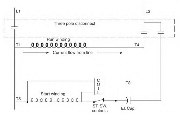
FIGURE 4.37 This three-pole switch connection will eliminate the "open
and close" cycling of the contacts.
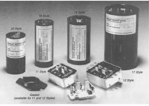
FIGURE 4.38 Electronic switches.
Electronic switches operate on the same principle as the potential relay.
Figure 4.38 shows some of the switches and their mounting assemblies.
The circuitry of the solid state electronic start switches is completely potted and sealed, making them ideal for dirty locations. Because they have no moving parts, they aren't affected by vibration or extra contact closure during motor coast-down.
This switch has voltage-sensing circuitry that switches off the start winding at a preset voltage. If the motor is overloaded or if there is a power interruption, the switch will reconnect the start winding at about 50 percent of synchronous speed.
Electronic switches are made for split-phase, capacitor-start, and two- value capacitor motors. The same switch will control two-, four-, and six-pole motors. The only two requirements are that the switches have the right voltage rating and a large enough ampere rating.
The electronic switch will control any size motor that draws less than the switch's ampere rating. (It's very important that the ampere rating of the switch is as high as or higher than the motor's nameplate ampere value.) The cutout voltage values for 115-volt switches are 130, 147, and 165 volts. The cutout voltage values for 230-volt switches are 260 and 310 volts.
To find the required voltage, run the motor with no load on its rated voltage.
Isolate the start winding from the line and record the voltage across it (T5 and T8). Select a switch that has a voltage value rating closest to 80 percent of the voltage found across T5 and T8. (Be sure the ampere rating of this switch is equal to or higher than the motor's full load amperes.) If the motor has a coasting-type load, (for example, a radial arm saw), a special resistor is used to prevent high voltage from destroying the electronic components during coastdown.
These switches replace the switch contacts and centrifugal devices for all split-phase, capacitor-start, and two-value capacitor motors.
Time-Delay Electronic Start Switch
Time-delay electronic start switches shut off the start winding at a predetermined time. They are available in l/-i second, 1/2 second, and 1 second delay time. If the motor stalls or doesn't get up to speed by the time the contacts open, the motor must be restarted to reconnect the start winding.
(If the thermal device doesn't trip, the run winding will be destroyed.) It is possible to plug (reverse while running) the motor with this switch.
(A motor with a centrifugal device has to slow enough for the contacts to close before it can be reversed.)
The same switch will operate capacitor-start, split-phase, and two-value capacitor-start motors of two to eight poles. Horsepower ratings are from the smallest motor to 5 hp. The voltage ratings of these switches are 115 and 230 volts. Ampere ratings are 30 amperes and below.
These switches will replace a motor's stationary contacts and centrifugal device.
Heat-Activated Start Switch
Many sealed refrigeration compressors have heat-activated start switch controls (Fig. 4.39). When the motor starts, the start-winding current flows through a bimetallic strip. The bimetallic strip quickly heats, bends, and opens the start-winding contacts.
A small heat element next to the bimetallic strip is connected parallel to the contacts and in series with the start winding. It bypasses the start switch contacts. After the switch contacts open, a small current through the start winding heats the element and keeps the bimetallic strip hot. As the motor runs, the bimetallic strip stays hot enough to keep the switch contacts open.
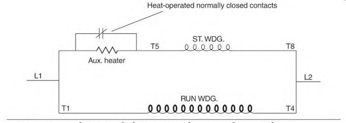
FIGURE 4.39 Schematic of a heat-operated start-winding switch.
The motor won't start if it's restarted before the bimetallic strip cools and reconnects the start-winding contacts. A thermal protective device should trip and shut off the power. The thermal protective device is usually self-resetting, and by the time it cools off enough to restart the motor, the heat-activated start switch has reset.
Current Relay Start Switch
The current relay start switch is used on single-phase motor applications where a stationary switch and centrifugal device aren't practical. (A submersible deep well water pump is a good example.) This application requires that the motor and pump be pulled up from the bottom of the well to be serviced if the start winding controls are mounted in the motor.
A current relay start method makes it possible to locate the start switch contacts and capacitor where they are accessible. (Capacitors and switch contacts need servicing more frequently than the rest of the motor.) Another advantage the current relay has is that only three cables are needed to power the pump motor and control the start winding.
Current Relay Start Switch Connections
The current relay switch in Fig. 4.40 is connected to the three motor terminals marked C (common), S (start), and R (run). The common lead (C) connects to one side of the start winding and one side of the run winding.
The other side of the run winding (R) is in series with the relay coil and line 2. The start winding (S) is in series with the switch contacts, the capacitor, and line 2.
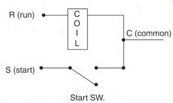
FIGURE 4.40 Current-operated start switch.
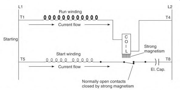
FIGURE 4.41 Schematic of the current relay as the motor starts. The current
of the inn winding (through the coil) pulls the contacts closed.
Function of the Current Relay Start Switch
The run-winding current continuously flows through the current relay's coil.
When the motor starts, high run-winding current pulls the (normally open)
start contacts closed (Fig. 4.41). The start-winding circuit is now connected to line 2, and the motor starts. As the rotor accelerates, ampere flow becomes lower in the run-winding and relay coil. At 75 to 80 percent of synchronous speed, the relay coil can no longer hold the contacts closed. The contacts drop open and the start winding is disconnected. The run winding will now pull the rotor up to full speed (Fig. 4.42). The relay coil's ampere rating must fit a motor's run-winding ampere demand. A motor that's too small won't draw enough amperes to close the switch contacts. A motor that's too large will draw so many amperes that the contacts won't drop open.
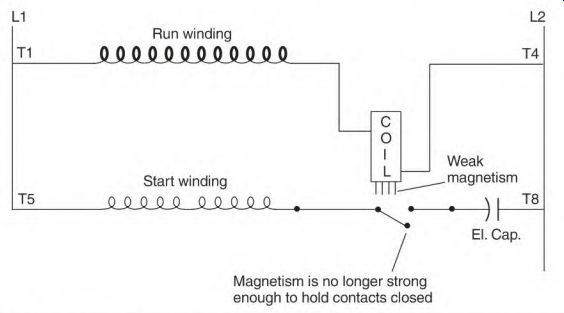
FIGURE 4.42 Current relay contacts in the run position.
Most current relay switch contacts fall open by gravity. For this reason, the relay must not be mounted at an angle. Even a slight tilt will prevent the contacts from falling open. All-angle current relays have spring-loaded contacts. A relay stamped "this side up" isn't all-angle.
A pulsing-type load may cause the contacts to close every time the load peaks. This overheats the start winding and the capacitor and causes the switch contacts to prematurely fail.
Section 4 Review
1. The start winding of a shaded-pole motor is a single copper band (55). T F
2. The speed of the shaded-pole motor is determined by the load (56). T F
3. The split-phase motor has both start and run windings across the line when it starts (58). T F
4. Both start and run windings can be energized continuously (58). T F
5. The split-phase motor has less starting torque than the capacitor-run motor (59). T F
6. Most split-phase motors are replaced-rather than repaired-if there is a winding failure (58). T F
7. The capacitor-run motor operates continuously with both start and run windings in the circuit (59). T F
8. How many moving parts are in the capacitor-run motor (59)?
9. The multispeed capacitor-run motor's RPM is governed by the speed selection, regardless of the load (159-160). T F
10. The capacitor-run motor is usually replaced if there is a winding failure (61). T F
11. The capacitor-start motor has high starting torque because of its electrolytic capacitor (61). T F
12. The start switch is usually the first component to fail in the capacitor- start motor (62). T F
13. The main cause(s) of dead spots are (63)
a. faulty contacts.
b. a worn rotor device.
c. worn thrust washers.
d. all of the above.
14 If thrust washers keep the rotor out of alignment with the stator (off magnetic center) the motor's amperes decrease (63). T F
15. It's more economical to replace the original start switch mechanism of the capacitor-start motor with an electronic start switch, because it has no moving parts to adjust (64). T F
16. DC current will slow a coasting squirrel cage rotor, but not lock it (64). T F
17. A continuous high ohmmeter reading means a capacitor is (64)
a. open.
b. shorted.
c. has no problem.
18. Voltage stored in a capacitor can damage an ohmmeter (64). T F
19. A motor with an open capacitor won't start (65). T F
20. If an electrolytic capacitor is open or shorted, the motor won't start (65). T F
21. Overheating will weaken an electrolytic capacitor (65). T F
22. A start winding will overheat if not shut off within 3 seconds (66). T F
23. A capacitor-start motor will be insulated better than when it was new if it is rewound by a reputable electric motor service center (66). T F
24. A dual-voltage start winding has three equal circuits (66). T F
25. The number sequence for connecting a dual-voltage single-phase motor can be remembered using the phrase "in on the s, out on the S." (68)
26. A single-phase motor normally has a low power factor (69). T F
27. A low power factor can be mistaken for shorted turns (69). T F
28. The data between T1 and T2 is the same as between T5 and T8 (70). T F
29. The comparison test is the best way to check for shorted turns in a dual- voltage run winding (70). T F
30. The term "in on the odds and out on the evens" applies to both the start and run windings (70). T F
31. A dual-voltage capacitor-start motor won't start or run with an open in one of its run circuits (71). T F
32. A motor that has been submerged in water must be replaced (71). T F
33. What is the purpose of the oil-filled capacitor in a two-value capacitor- start, capacitor-run motor (73)?
34. The start winding will be destroyed if the oil-filled capacitor is shorted (73). T F
35. If the oil-filled capacitor is removed, the two-value capacitor-start, capacitor-run motor won't start (73). T F
36. What are the three rules for electrolytic capacitor connections (73)?
37. How many electrolytic capacitors can be connected in series (73)?
38. Electrolytic capacitors connected in series are always used on high voltage, and the single capacitor is always used on low voltage (73). T F
39. When one capacitor is open in a multiple-capacitor system-two in parallel in series with two in parallel-what are the two factors that decrease the motor's starting power (175-176)?
40. When one capacitor is shorted in a multiple-capacitor system-two in parallel in series with two in parallel-the total capacitance is increased (76). T F
41. In the term "phase angle"-phase meaning winding, angle meaning the time current flows-a comparison is being made between the time current peaks in one winding (phase) and the time (angle) the current peaks in another winding (76). T F
42. When the degrees of the phase angle and the degrees of separation between two windings (phases) match, the motor's torque is at its highest (76). T F
43. The voltage rating of an oil-filled capacitor should be the same as the applied voltage (77). T F
44. Voltage generated when a two-value capacitor motor coasts can become destructively high (78). T F
45. Dual-voltage motors always have capacitors rated for high voltage (78). T F
46. Capacitors connected in series are always rated for high voltage (78). T F
47. Fractional horsepower single-phase motors with worn bearings are usually replaced rather than repaired (81). T F
48. Thermal protective devices (that are self-resetting) shouldn't be used on machinery that can cause injury (81). T F
49. Overload current flowing through P2 causes a thermal protective device to trip (82). T F
50. P3 is always connected to a winding circuit (that will draw high current) when the motor is overloaded (82). T F
51. The thermal protective device will be destroyed if P3 is connected to line 1, when P1 is connected to line 2 (83). T F
52. P2 is always connected to windings that should bypass the heat element (83). T F
53. When a dual-voltage motor is connected low voltage, only half of the run winding is connected to P3 (84). T F
54. A fully loaded dual-voltage motor will have the same number of amperes through its run-winding coils on low voltage as it has on high voltage (184-185). T F
55. High ambient temperature can cause thermal protective devices to (85)
a. not trip.
b. trip needlessly.
c. all of the above.
56. The potential relay start switch can replace a motor's stationary switch and rotor device, regardless of its speed (86). T F
57. The voltage across the run winding controls the potential relay's function (186-187). T F
58. The motor's horsepower rating determines the size of the potential relay's contacts (87). T F
59. Voltage across the start winding will increase to a value above line voltage when the rotor reaches 75 to 80 percent of synchronous speed (187-188). T F
60. A coasting load causes excessive wear on the potential relay's components (188-189). T F
61. A bleeder resistor will keep a potential relay from cycling (188-189). T F
62. An electronic switch-that operates the same as the potential relay-has the same voltage/horsepower restrictions (190-191). T F
63. A coasting load won't affect the electronic switch (92). T F
64. A time-delay electronic switch operates regardless of the motor's speed (92). T F
65. A heat-activated start switch is compatible with refrigeration compressors, because a compressor will stay off long enough for the switch to reset (192-193). T F
66. A thermal protective device is vital when the heat-activated switch is used (93). T F
67. The current relay depends on the amperes of the run winding to function (94). T F
68. The current relay can't close the contacts if the motor is overloaded (94). T F
69. The current relay's ampere rating has to match that of the motor (94). T F