AMAZON multi-meters discounts AMAZON oscilloscope discounts
Industry uses more three-phase induction motors than other types of motors because they require less maintenance. The squirrel cage rotor is the motor's only moving part (excluding ball bearings). This motor is smaller physically (per horsepower) than single-phase or DC motors (Fig. 5.1). Sizes range from fractional to thousands of horsepower (Fig. 5.2). Three-phase power is divided among three lines. This reduces the supply line's wire size.
The three-phase induction motor has no switching or commutation of circuits. This makes it possible to use very high voltage. High voltage allows the motors to be designed in large sizes (as volts go up, amperes go down- watts and horsepower stay the same). The speed of the three-phase induction motor is governed by the number of poles in the stator and the hertz of the power source (like the single-phase induction motor).
Components of the Three-Phase Motor
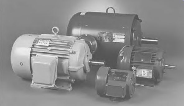
FIGURE 5.1 Small three-phase induction motors. Lincoln Electric Motors.
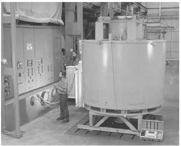
FIGURE 5.2 A large three-phase synchronous motor. Allen-Bradley Electric.
Figure 5.3 shows all the three-phase motor's components:
• Rotor and fan
• Stator core
• Shell and frame
• End brackets
• Bearings
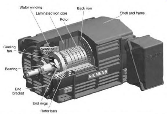
FIGURE 5.3 A three-phase induction motor with all its components shown. Siemens.
Rotor and Fan
The squirrel cage rotor in Fig. 5.3 is cut open to show some of its rotor bars.
The rotor bar's size, shape, and effect are covered in depth later in this section, starting with "Amperes and Rotor Bar Design." The rotor has a cooling fan attached to it. Fans can be located internally, externally, or both. Air moving over the windings and core iron removes most of the heat from a motor. (The rest escapes through the motor's shell.) Most cast aluminum rotors have fan blades cast in their end rings.
Ventilation is the same for either direction of rotation.
Stator Core
The motor's location should not restrict intake or exhaust air movement.
The stator core is made of thin steel sheets called laminations. A laminated core is necessary to reduce (heat-causing) eddy current. The thickness of the laminations is governed by the frequency for which the motor is designed.
(Higher frequency develops greater eddy current and requires thinner laminations.)
The steel used in laminations is very permeable, meaning that it changes polarity with minimal internal friction. Magnetism is constantly changing in the laminated core of the three-phase motor.
Slots are cut in the laminations with a laser or punch press. The slotted laminations are stacked to a thickness required for the motor's horsepower rating.
The iron below the slot (hack iron) (Fig. 5.3) completes the magnetic path from pole to pole. A two-pole motor will have much thicker back iron than a six-pole motor. The AC motor (unlike the DC motor) doesn't use its outer shell to complete the magnetic path.
Some motors have ventilation slots between the core and the motor's shell. The outside or back iron of the (laminated) core should be as symmetric as possible, because it affects the motor's magnetic path.
Shell and Frame
The motor's shell is made of cast iron or pressed steel. The shell supports the end frames (end bells), which contain the motor's bearings.
Most motors have mounting feet that are part of-or are welded to-the shell. The c-flange design is mounted from the shaft end bell (or end frame). A cast iron frame is more rigid than a pressed steel frame, making it better for motors of 10 horsepower and larger. Cast iron components, however (such as mounting feet and end bells), can break from rough handling.
Properly designed pressed steel frames are better than cast iron for motors under 5 horsepower. Their lighter weight makes them easier to handle.
Short compact motors are stronger than long motors. The rotor of a short- framed motor has less distance between its bearings, lessening the chance of rotor drag. A short compact motor handles rough duty (such as a chain drive or a direct driven vibrator) very well.
Electric motors have NEMA and European standard frame dimensions.
The frame dimensions include shaft size, height, length, and mounting hole locations.
End Brackets
The motor's end brackets are made of cast iron, cast aluminum, or pressed steel. They support the sleeve (or ball) bearings.
The end brackets of large sleeve bearing motors contain an oil reservoir.
(An oil ring rides on the shaft and brings oil to it from the reservoir.) Small sleeve bearing motors have oil wicking which is retained around the bearing in the end bracket.
End brackets with ball bearings may or may not have allowances for greasing the ball bearings. This is covered in detail under "Bearing Maintenance" in Section 7.
Ventilation slots are part of the end bracket if the motor is classified as open. An open motor can be open, dripproof, or splashproof. Windings can be seen in an open motor. A dripproof motor protects the windings from falling water. Splashproof motors have baffles that shield the windings from above and below, but still allow free movement of air through the motor.
Totally enclosed, fan-cooled frames are dustproof and have no ventilation slots in the end brackets. The shaft is extended through the rear end bracket with a fan mounted on it. (A guard shell covers the fan.) Explosion-proof motors are built strong enough to contain an explosion of gasoline vapor, without emitting flame or sparks into the surrounding air.
Bearings
Electric motors have ball, roller, or sleeve bearings. The majority of motors have ball bearings. Some large motors and special-duty motors have roller bearings.
Bearings are covered in detail under "Bearing Maintenance" in Section 7.
Operation of the Three-Phase Motor
The operating characteristics of the three-phase induction motor are directly linked to the three-phase alternator that powers it. The positioning of the stator poles in both is identical. The voltage sine wave (Fig. 5.4) produced by the three-phase alternator is a picture of how the poles are connected in both the motor and the alternator.
The alternator has three single-phase windings, spaced 120 degrees apart in its stator (Fig. 5.5). Figure 5.6 shows the coils that form the first pole of phase A, phase B, and phase C. If a magnet is passed over the coils, the voltage generated in them produces a sine wave like the one shown in Fig. 5.7. The voltage produced is spaced 120° apart (like the coils). At 60 Hz, 120° in time equals 1/280 second. Voltage peaks in each of the three phases 1/280 second apart. Figure 5.8 shows the polarity of six three-phase poles and how they fit the sine wave.
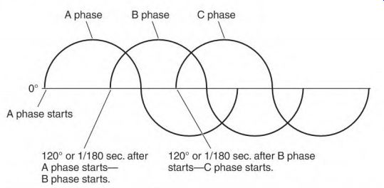
FIGURE 5.4 The three-phase voltage sine wave. The shape of the sine wave makes
it easy to compare with the poles of a stator.
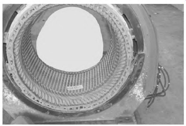
FIGURE 5.5 The stator of a three-phase alternator has windings that are identical
to a three-phase motor. Smith Services.
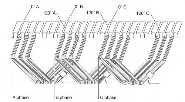
FIGURE 5.6 One pole from each of the three phases. (Poles are separated 120
electrical degrees from each other.)
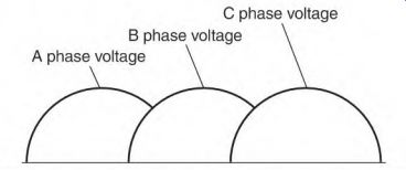
FIGURE 5.7 Voltage sine wave created by the three poles (if a magnet is passed
over them).
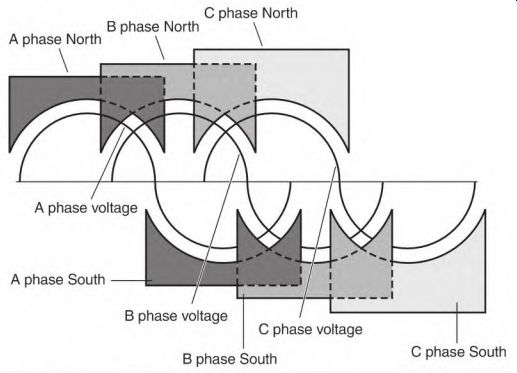
FIGURE 5.8 Windings of a two-pole stator are connected to fit the sine wave.
The Rotating Magnetic Field in a Three-Phase Motor
A three-phase motor has three single-phase windings. They are positioned 120° apart, identical to those of the three-phase alternator previously described. The following is a simplified version of the three-phase rotating magnetic field.
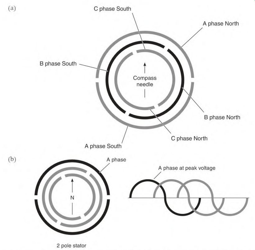
FIGURE 5.9 (a) Two-pole stator showing a north pole and a south pole for each
phase, (h) When DC is applied to the A phase, the compass aligns itself as
shown.
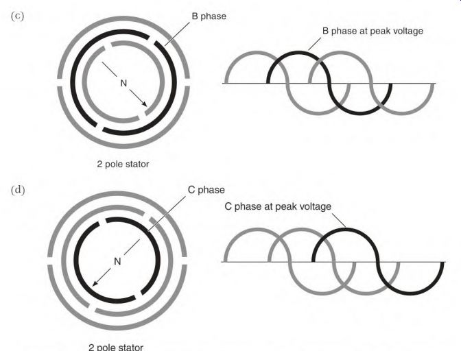
FIGURE 5.9 (c) The compass needle moves 120 degrees when DC is applied to
the B phase, (d) When DC is applied to the C phase, the compass needle moves
another 120 degrees.
Figure 5.9a is a two-pole stator with a compass needle centered in it.
When DC is applied to phase A, the compass needle will align as shown in Fig. 5.9b. Applying DC to phase B moves the compass needle 120°, aligning it with phase B (Fig. 5.9c). And DC applied to phase C moves the compass needle another 120°, aligning it with phase C (Fig. 5.9d). Applying DC as shown in Fig. 5.9 creates a rotating magnetic field (like three-phase power). Rotation is produced when three voltages (spaced 120° in time) are applied to three phase windings (spaced 120° from each other). Alternate phases will reach peak magnetism at 1/280-second intervals, resulting in a rotating magnetic field. The moving magnetic lines of force cut the bars of the rotor's squirrel cage winding, creating poles in the rotor iron.
Single-Phase Condition
A three-phase motor won't start with one of its lines open. When one line is open, single-phase is applied to two of the motor's three windings and one winding is inactive. Two of the three single-phase windings (spaced 120° apart) are energized. Current in the two windings is in unison. Magnetism of both windings peaks at the same time, as though they were one winding.
There's no rotating magnetic field. Since the rotor pole magnetism has no stator pole magnetism to react to, there is no torque. A pulsing, high current will flow in the rotor and the stator windings.
If the shaft is spun fast enough, the motor will run as a single-phase motor. The motor's power, however, drops to slightly more than one-half its nameplate value. If a fully loaded motor is running when single phasing occurs, the energized part of its winding overheats and chars. This is explained and illustrated in Section 6, Fig. 6.35.
Amperes and Rotor Bar Design
The motor's amperes and torque are affected lay various designs of the rotor bars. The type of metal used, the bar shape, and size all affect the motor's amperes and torque (from zero to full speed).
Cast aluminum is the most common metal used in squirrel cage rotors.
Aluminum makes it easier and cheaper to mass-produce rotors. However, because of the low melting temperature of aluminum, rotor bars and end rings have to be oversized to carry the high starting current. (This reduces the amount of iron that is needed for the magnetic lines of force.) The overall size of the rotor must be larger when aluminum is used instead of copper or brass.
Rotor bars made of copper (and/or other alloys) conduct high-ampere flow (that would melt aluminum). An example is the small copper rotor bars that are used in high-slip motors. Their small size gives them high resistance, which limits the amperes in the rotor winding.
Ampere flow in all motor windings is very high when a motor starts. The motor's current demand (the instant it starts) is the same as the locked rotor current. The squirrel cage winding (with locked rotor) is similar to a shorted secondary in a transformer. (If both ends of each turn in a transformer's secondary were welded to two separate bars of copper, the resulting ampere flow would resemble that of a locked squirrel cage rotor.) When the rotor is locked, the bar size and the resistance of the bar's metal are all that control the current flow in its winding. (Large rotor bars have greater area for current flow than small rotor bars.) Ampere demand can be many times the motor's nameplate value.
When the motor is at 0 RPM (locked rotor), the slip is 100 percent.
(Percent of slip is synchronous speed minus the rotor speed divided by synchronous speed times 100.) At this time, the rotating magnetic field is cutting the squirrel cage winding bars at maximum hertz. As the speed of the rotor increases, slip decreases, and the rotor hertz decrease. The power supply hertz times percent of slip equals rotor hertz. Rotor hertz ranges from 0.3 to 1.5 Hz at full-load speed (depending on the rotor bar design). When the rotor hertz is this low, fewer lines of force cut the rotor bars, so less power is transformed into them. Since the rotor's power comes from the stator, the stator amperes drop to normal (at rated speed). Phase (in the term phase angle) means a winding. (The squirrel cage is the rotor's winding.) Angle means time.
Angle, in this case, is a reference to the time that the current flows in two respective windings and creates magnetism. Phase angle is the difference (in time) between when one winding and another winding reach peak magnetic power.
The phase angle has a bearing on a motor's torque. A motor with a good phase angle (when starting) has high starting torque, but not necessarily a high ampere demand. High amperes don't always mean high starting torque.
When a squirrel cage induction motor is energized, there's an instant of locked rotor condition. At this time, magnetic lines of force of the rotating magnetic field penetrate the rotor's iron only about 3/8 inch. A voltage is transformed into small rotor bars located within this 3/8 inch (Fig. 5.10). The ampere flow in the rotor poles (transformed amperes) and the ampere flow in the stator poles (line amperes) will peak in value at nearly the same time.
When this happens, the motor has a good phase angle (near 90°) between stator and rotor windings.
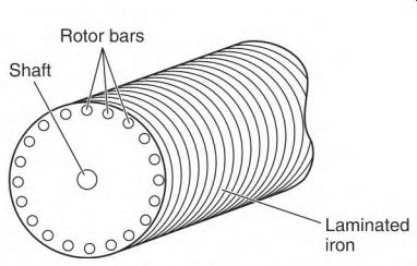
FIGURE 5.10 Small rotor bars, located close to the surface of the rotor, will
have ampere flow that nearly matches (in time) the stator amperes.
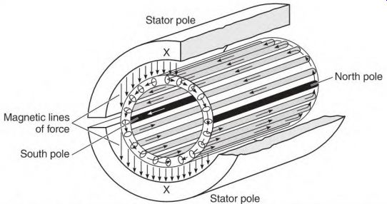
FIGURE 5.11 Poles form in the rotor's iron as current flows in the rotor bars.
Poles form in the rotor iron because of ampere flow in the rotor bars.
When peak magnetism in the rotor poles and stator poles occurs at nearly the same time, the result is very high starting torque (Fig. 5.11). Ampere flow is restricted by the small size of the rotor bars. Power transformed into the rotor bars comes from the stator winding. (Ampere flow in the stator is normally high when starting.)
Large Rotor Bars
As with small rotor bars, the power transformed into large rotor bars comes from the stator pole's rotating magnetic field. (Large bars can carry higher current than small bars.) The current flow forms poles in the rotor iron.
Large rotor bars (because of their shape) are surrounded by a lot of iron.
Magnetizing the surrounding iron causes a delay of current flow in the bars (inductance). This delay in current flow (in the rotor bars) causes peak magnetism to occur later in the rotor poles than in the stator poles. The magnetic power of the stator poles will have peaked (and decayed to a lower value) when the magnetic field of the rotor reaches its peak power. The result is a poor phase angle.
The torque-producing magnetic interaction of the two windings is highest when both windings reach peak magnetism at nearly the same time. Low starting torque is the result of out-of-step peak magnetism, not the number of amperes in the squirrel cage winding.
Code Letter
The code letter (found on the motor's nameplate) determines a single-phase or three-phase motor's inrush amperes. Use the code letter and the following formulas to select the right overload protection:
Code letter value x hp x 1000 -r voltage for single-phase
Code letter value x hp x 577 voltage for three-phase (1000 x 1.73 = 577)
For 40 horsepower, 440 volts, three-phase, code F (5.3 is midrange), 5.3 x 40 x 577 -f 440 = 278 inrush amperes
Three-phase motor controllers are horsepower rated. The overload protection size is selected to fit each individual motor.
Torque and Speed
Torque is twisting force, measured in foot-pounds, inch-pounds, and inch- ounces. The formula combines torque and speed (RPM) to find horsepower: torque x RPM h- 5250 = hp
Torque and RPM terms are explained in Fig. 5.12. Understanding these terms is essential when fitting a motor to a load.
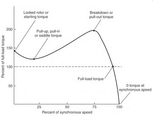
FIGURE 5.12 Torque terms from 0 RPM to synchronous speed.
Starting torque (locked rotor torque) is the amount of torque that is available to break the load away from a standstill position. (Breakaway torque is another name used for this torque value.) Starting torque is a very important value when fitting a motor to a load.
For example, an air compressor (starting against compression) requires very high starting torque.
Saddle torque is a dip in the motor's torque output that occurs between starting and pull-out (or breakdown) RPM. If the motor's (saddle) torque drops below the load torque demand, the motor will stop accelerating. The motor windings will overheat and fail (unless the overload protection trips). Saddle torque is a problem found in two-pole motors that have a large- diameter bore. A special connection called the interspersed connection is used to minimize saddle torque. The problem occurs when a motor has been rewound and the connection is not used.
Breakdown (or pull-out) torque is the maximum possible torque that a motor can develop, and it can occur at any RPM between starting and full load.
If breakdown torque occurs close to nameplate RPM, just a few RPM less than nameplate RPM will cause the motor to overheat.
A small reduction in RPM, caused by an overload, results in a large increase in horsepower output (Fig. 5.13 design A). An increase in horsepower output is accompanied by an even larger increase in amperes (and heat).
Full-load torque is the maximum torque the motor can have continuously (without overheating). This torque occurs at the nameplate RPM. The preceding torque values vary with rotor bar design. The motor's design letter-found on the motor's nameplate-identifies the torque characteristics of a motor.
Design Letter
A three-phase motor's design letter (found on the nameplate) is a very important factor in selecting a motor. Figure 5.13 shows the torque and speed characteristics of each letter.
Design A
The design A motor has large rotor bars, so it will demand high starting current. However, despite having high starting current, it has only moderate starting torque. Therefore, the motor's protection has to be adjusted accordingly.
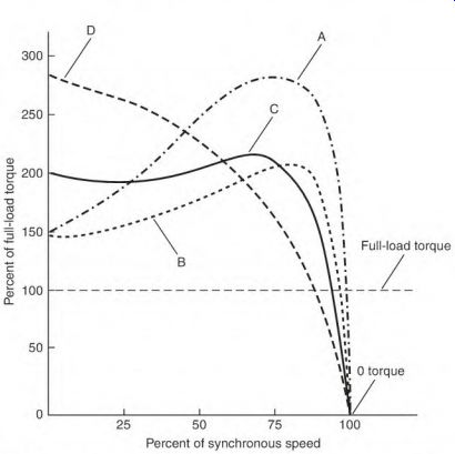
FIGURE 5.13 A design letter is given to a rotor. The shape, size, and location
of the rotor bars affect the design letter.
This motor has very high torque near its rated RPM. Its large rotor bars keep the rotor's full-load speed close to the synchronous speed. (This can be compared to a paddle wheel in a stream of water; with large paddles the wheel slips very little and rotates at close to the water's speed.) The design A motor will keep its load at nearly constant speed.
The design A motor will overheat even if it's overloaded only a few RPM (below its nameplate rating). Higher torque (at lower speed) results in a large increase in horsepower output and ampere demand.
Some efficiency is lost with rotor slip. The torque curve of design A is similar to that of a high-efficiency motor.
Design B
Design B is a standard industrial motor. It has average starting torque and moderate starting current. This motor has a lower full-load RPM than that of the design A or the high-efficiency motor. Most design B rotors use low-cost cast aluminum.
FIGURE
5.14 The rotor bar used in a design C rotor has two shapes that are linked.
Design C
The design C motor has higher starting torque and slightly greater slip than the design B motor. Its rotor bars are two sizes, linked together. A small bar near the rotor's surface is linked to a larger bar deeper in the iron (Fig. 5.14). The small part of the bar gives the rotor high starting torque. The deeper part will reduce the slip. Starting current is moderate, limited by the size of the small bar. The bars are usually made of copper or brass (making the motor more costly). They are more likely to crack because of their shape and the type of metal used.
Design D
Design D is for loads requiring extremely high starting torque but not high torque near rated speed. This design is suited for a heavy flywheel load or for a centrifuge load. This motor can power a heavy flywheel load up to the nameplate RPM without developing excessive heat. (Its small rotor bars limit the starting current.)
A metal shear is an example of a load that stores energy in the weight of its moving flywheel. The shear slows its motor's RPM below the nameplate value each time it cuts metal. Because of the small rotor bars, the torque and (stator winding) amperes aren't excessively high when the motor's speed is lowered.
The design D motor can handle wide RPM swings without developing excess heat in its stator windings.
Design Letter Summary
Industry presents a wide range of speed and torque demands for the three-phase induction motor. Four-pole motors are the most common, followed by two-pole, then six-pole motors. There are many different torque demands, from zero to full-load speed. Some loads require very high starting (breakaway) torque. Other loads require little starting torque, but demand higher torque as the speed increases. The design letter helps in selecting the right motor.
The design A and the high-efficiency motors develop high torque just a few RPM slower than their rated RPM. Because of this characteristic, they are the choice for loads that require a fairly constant speed.
Liquid-moving pumps and air-moving equipment have similar loading characteristics. If the RPM is increased a small amount over the rating, the horsepower demand increases to the cube of the RPM change. (The RPM of the replacement motor has to be the same as the original for this type of load.) Most three-phase induction motors operate very close to their nameplate RPM when rated load is applied. Less than rated load allows the shaft to turn at a slightly higher RPM than its nameplate value (slip can vary from 0.3 to 5 percent). Standard three-phase induction motors under 10 horsepower have greater slip than those over 10 horsepower. Slip for standard motors above 50 horsepower is 1 percent or less.
Introduction to Three-Phase Motor Types
The nine-lead three-phase induction motor is the most popular motor for industrial use. It ranges from fractional to hundreds of horsepower. The 12- lead induction motor is very similar to the nine-lead motor. Other induction motors covered are multispeed, multimode, and wound rotor motors. The synchronous motor and the brushless DC motors are also covered.
The Nine-Lead Induction Motor
The nine-lead three-phase induction motor can be used on two voltages. It will be connected as either wye or delta. Figure 5.15 is a schematic of a nine- lead wye connection. The delta connection in Fig. 5.16 is also designed for both voltages.
An ohmmeter can be used to determine whether the motor has a wye or delta connection (if there isn't a connection nameplate). As the schematics show, a nine-lead wye connection has three circuits with two leads and one circuit with three leads. The delta connection has three circuits with three leads each.
Each phase (in all nine-lead dual-voltage three-phase motors) is divided into two equal circuits. Regardless of the number of poles, one-half are in each circuit. The nine-lead motor has a 2-to-1 difference in its voltage rating.
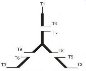
FIGURE 5.15 The most common connection found in small motors in the nine-
lead wye connection.
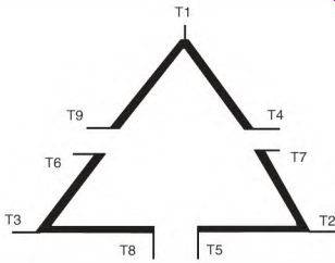
FIGURE 5.16 The nine-lead delta connection is usually found in motors of 10
horsepower and above.
Each pole has the same voltage across it, whether the motor is connected high or low voltage.
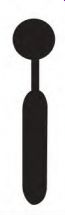
A telephone keypad (Fig. 5.17) simplifies three-phase connections.
Exactly one-half of each phase is connected between two keys. For example the A phase, one half of its winding is connected between keys T1 and T4, and the other half between key T7 and the blank key below it.
The keypad can be used as a reference for wye, delta, 12-lead, 10-lead, and wye-delta connections. The keys have windings connected to them as shown in Fig. 5.17.
A wye-connected motor will have the bottom three keys tied together (internally) to form the wye connection.
For the 10-lead connection, lead number T10 is connected to the internal wye.
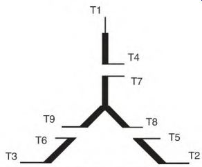
FIGURE 5.18 The nine-lead wye schematic.
Internal connection
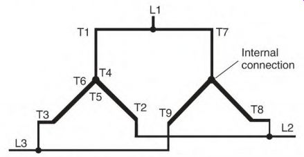
FIGURE 5.19 The low-voltage (two-wye) connection.
Both wye- and delta-connected motors combine the same lead numbers for high voltage. In both connections, each phase is connected in series for high voltage. In the wye connection (Fig. 5.20), a circuit from line 1 to line 2 goes through two phases.
Nine-Lead Multiple-Wye Connection with T10
The internal wye sometimes has lead T10 connected to it. This lead is connected to T4, T5, and T6 when the motor is connected low voltage (Fig. 5.21). When the motor is connected high voltage, T10 is insulated and not used.
The purpose of T10 is to balance the voltage (and the resulting current) between the wye connections. Ideally, wye connections would have no voltage or current difference between them. (In reality, there is always some unbalance.) The most common reason for the unbalance is a slight difference in air gap around the rotor. Connecting T10 as shown in Fig. 5.22 ...
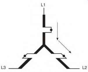
FIGURE 5.20 The high-voltage wye connection showing where the current flows
from line 1 to line 2.
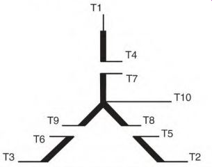
FIGURE 5.21 The 10-lead dual-voltage motor.
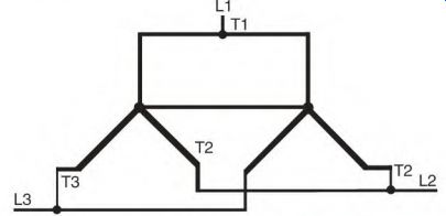
FIGURE 5.22 Multiple wyes are often connected together internally.
... equalizes the voltage and current between the two connections. The result is a better magnetic balance between the stator poles.
For example, a 30-horsepower, two-pole, multiple-wye-connected motor that powered a metal polisher had to be rewound. When the motor was rewound and reinstalled, a pattern developed on the metal, instead of a mirror finish. The wye connections were joined, and the pattern disappeared.
Larger nine-lead motors have multiple wyes connected internally. The wyes are usually connected (internally) to a common wire, as shown in Fig. 5.22.
Thermal Protector for the Nine-Lead Wye-Connected Motor
A thermal protector for the dual-voltage (230/460-volt) wye-connected three- phase motor is shown in Fig. 5.23.
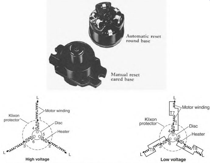
FIGURE 5.23 A three-phase thermal protector. Klixon.
Automatic rcsL-r round bas-c Manual reset cared base
This protection is designed for small wye-connected motors. (The delta connection is seldom used in motors under 5 horsepower.)
In Fig. 5.23, there are three current-monitoring heat elements. High current through these heat elements will trip open the protector's contacts.
They are located between 1 and 4, 2 and 5, and 3 and 6.
The motor's internal wye is connected permanently to terminals 1, 2, and 3 of the thermal protector. These leads are the ends of the phases. (In a 12-lead motor, they are labeled T10, T11, and T12.) P4, P5, and P6 bypass the heat elements. When the motor is connected low voltage, they are connected to the motor's corresponding T leads (P4 to T4, P5 to T5, and P6 to T6). If connected high voltage, P4, P5, and P6 aren't used and are separately insulated.
If line 1, 2, or 3 becomes open, the motor operates on single phase. (The term single-phased describes this condition.) When a motor is single-phased, its power drops to approximately one-half of its horsepower rating. The amperes increase through two of the heat elements, causing the protector's contacts to open and disconnect all the motor's circuits. The thermal protector uses the amperes of T7, T8, and T9 to protect the motor, whether the connection is high or low voltage.
Nine-Lead Delta Connection
In the delta connection, T1, T2, and T3 are the points of the delta (Fig. 5.24). They contain the end half of one phase and the start half of the next phase.
In the start half of phase A, lead T1 is connected to (the end) half of phase B. One-half of phase A starts at T1 and ends at T4. Lead T7 completes phase A, …
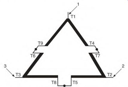
FIGURE 5.24 The points of the delta connection are numbered T1, T2, and T3
in the nine-lead schematic.
... ending at T2. Phase C starts at T2 and ends at T5. Lead T8 completes phase C, ending at T3. Phase B starts at T3 and ends at T6. Lead T9 completes phase B, ending at T1.
When the delta is connected low voltage, each line is connected to three motor leads. Line 1 is connected to T1, T6, and T7; line 2 to T2, T4, and T8; and line 3 to T3, T5, and T9. Figure 5.25 shows how the circuits of each phase are connected in parallel.
Multiple-Delta Connection
The delta connection is found on motors above 5 horsepower. Larger nine- lead motors may have multiple deltas, connected internally. The external lead numbers are the same, and they are connected as described in Fig. 5.26.
Both delta- and wye-connected motors combine the same lead numbers for high voltage. Each phase is connected series in both connections. As shown in Fig. 5.27, each phase is connected across the line.
Twelve-Lead Connection
The 12-lead connection gives a motor greater versatility. A motor with this connection can be used on four different voltages.
In Fig. 5.28, the end of each phase is accessible by leads T10, T11, and T12. The rest of the leads (1 through 9) use the same lead number combinations as the nine-lead connection. Figures 5.29 through 5.32 show four different voltage connections that can be used on the 12-lead motor.
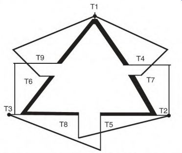
FIGURE 5.25 The delta connection connected for low voltage.
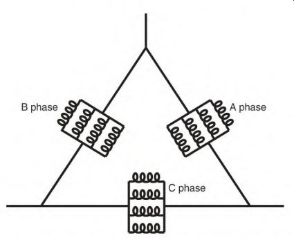
FIGURE 5.26 The multiple-delta connection is found in larger motors.
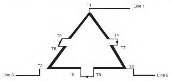
FIGURE 5.27 The delta connection connected for high voltage.
The lowest voltage connection is two delta (Fig. 5.29). The next-higher voltage connection is two wye (Fig. 5.30). (The two-delta voltage multiplied by the square root of 3 [1.73] equals the correct two-wye voltage.) The next- higher voltage connection is one delta (Fig. 5.31). This voltage is twice the two-delta voltage.
The highest voltage is one wye (Fig. 5.32) (twice the two-wye voltage). The voltage across each pole is the same on all four voltages.
The 12-lead connection can be connected part-winding start, using half-winding or two-thirds-winding start methods. The wye-start, delta-run, one-delta start, and two-wye run starting methods also work. (These start methods are discussed later under their separate headings.)
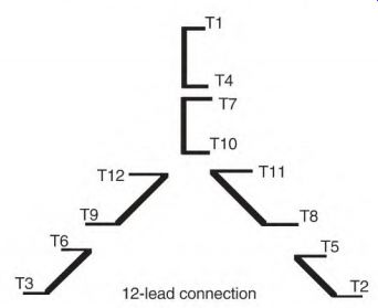
FIGURE 5.28 The 12-lead connection has the ends of each phase available for
both wye and delta connections. The rest of the lead numbers are the same as
those for a nine-lead wye or a delta connection.
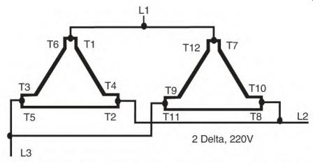
FIGURE 5.29 Two delta is the lowest voltage connection for the 12-lead motor.
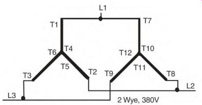
FIGURE 5.30 Voltage of the two-wye connection is 1.73 times that of the two-
delta connection.
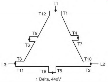
FIGURE 5.31 One-delta voltage is twice the value of two-delta voltage.
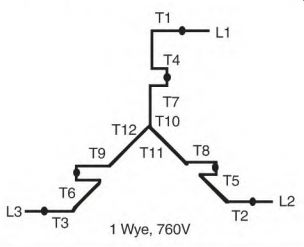
FIGURE 5.32 The highest voltage for the 12-lead connection is one wye-twice
that of the two-wye connection.
Multispeed Motors
Multispeed motors covered in this section have one or more windings. The selected speed operates as a single-speed induction motor. (There is a small amount of slip, which is governed by the rotor design.) They are physically large for their rated horsepower when compared to single-speed induction motors.
Single-Winding Two-Speed Motors
Three types of single-winding two-speed motors are covered in this segment: constant horsepower, constant torque, and variable torque. All have a 2-to-l speed ratio.
The two-speed windings have six leads that are switched and combined by a controller. The constant-horsepower and constant-torque motors use a one-delta and a two-wye combination. The variable-torque motor uses a one- wye and a two-wye combination.
The two-wye connection allows more current to flow than the one-delta or one-wye connection. This connection creates high torque (low speed) in the constant-horsepower motor and maintains the same torque (for both speeds) in the constant-torque motor.
The two-speed single-winding motor has a unique coil and pole arrangement. The pole width and spacing allow the motor to be switched from salient pole to consequent pole, and vice versa. Like a DC field pole, the salient pole is a wound pole. When the salient poles are connected so that the adjacent poles are of opposite polarity, the motor is in high speed.
Connecting all the poles of the same polarity creates the consequent-pole winding. Each pole's width is narrower than normal, leaving a space (iron) between the poles. This iron becomes a consequent pole. As a result, the number of poles is doubled. Doubling the poles cuts the speed in half.
The consequent-pole (low-speed) connection has a much lower power factor than the salient pole connection. It's common for the consequent-pole connection to draw full (or over) nameplate amperes with no load.
Constant-Horsepower Motor
The constant-horsepower motor has a single horsepower rating on its nameplate, with the same horsepower rating for both speeds. It's connected two wye for low speed and one delta for high speed (Fig. 5.33).
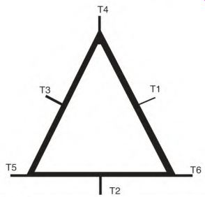
FIGURE 5.33 Schematic for a constant-horsepower motor.
If a constant-horsepower motor is connected low speed (two wye) and can lift 550 pounds 1 foot in 1 second, it will produce 1 horsepower.
Connected high speed, the one-delta connection doesn't allow as much current to flow (as the two-wye connection). The motor now can lift only 275 pounds, but lifts it 2 feet in 1 second, maintaining 1 horsepower.
The constant-horsepower motor has high torque on low speed and less torque on high speed. It is ideal for a drill press application. A large drill bit needs high torque and should turn slowly. A small drill bit doesn't require much torque, and normally it is turned at high speed.
Constant-Torque Motor
The constant-torque motor has two horsepower ratings on its nameplate.
The horsepower rating of its high speed is twice that of its low speed.
The connection is one delta for low speed and two wye for high speed.
If a constant-torque motor is connected low speed (one delta) and can lift 550 pounds 1 foot in 1 second, it is producing 1 horsepower. When connected high speed, the two-wye connection allows more current to flow. More current gives the motor the ability to maintain the same torque, but at twice the RPM of low speed. At high speed, the motor can lift 550 pounds 2 feet in 1 second, producing 2 horsepower.
The constant-torque capability makes the constant-torque motor much more applicable than the constant-horsepower motor.
Variable-Torque Motor
The variable-torque motor has two horsepower ratings on its nameplate. The low-speed horsepower rating is one-fourth that of the high-speed horsepower rating. The variable-torque connection (Fig. 5.34) is one wye on low speed and two wye on high speed. The one-wye (low-speed) connection has one-fourth the horsepower that the two-wye (high-speed) connection has. The horsepower/speed combination is very compatible with the horsepower demands of a fan load.
A 50-horsepower, four- and eight-pole variable-torque motor is an example. Synchronous speeds are used instead of actual nameplate speeds (that involve slip). On high speed (1800 RPM), the motor develops 50 horsepower and is connected two wye. The low-speed (one-wye) connection will develop 12.5 horsepower (0.25 x 50 horsepower) at 900 RPM.
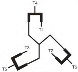
FIGURE 5.34 Schematic for a variable-torque motor. Heavy lines represent phase
winding location relative to lead position. This schematic does not show true
angle relationship.
When the speed of a fan is changed, the horsepower demand is not in proportion to the speed change. The horsepower must be changed to the cube of the ratio of the speed change. For example, 1800 -f 900 = 2 (ratio) The ratio cubed (or 2 x 2 x 2) = 8
A fan requiring 50 horsepower at 1800 RPM would need only 6.25 horsepower at 900 RPM (50 ^ 8 = 6.25 horsepower).
Any load requiring this type of horsepower/speed change ratio has a good potential for considerable savings in power cost. If the motor's speed can be lowered even a small amount and still meet the output demand, the power consumed will be reduced substantially. Air, liquid, conveyer belt, and auger loads all have similar speed/load power ratios, thus the potential for power cost savings.
Multispeed Multiwinding Motor
The multispeed multiwinding motor is usually constant torque or constant horsepower. The speed ratio for each winding is 2 to 1. Several of these windings are combined in some multispeed drill press motors.
If a multispeed motor has more than one winding, the higher-speed winding will have higher lead numbers. For example, the lowest speed will have numbers T1 through T7, the higher speed T11 through T17, and T21 through T27 on the next-higher speed winding.
Two-Speed Two-Winding Motor
A two-speed motor with a speed ratio that isn't 2 to 1-for example, 1200 RPM/1800 RPM-will usually have two single-speed windings. The lead numbers are T1, T2, and T3 for the low speed and T11, T12, and T13 for the high speed.
There's no internal connection between them, and they should be tested as two different motors.
If one or both windings are delta connected, the internal connection (described in Section 7, Fig. 7.4 under "Circulating Current in Multiwinding Multispeed Motors") must be used. A rewound motor draws excessively high amperes if this connection isn't used.
Multimode Nine-Lead Three-Phase Motors
Multimode motors are primarily used on oil well pumps. They must have high-slip rotors because of the uneven torque demand unique to oil well pumps. They also have special internal connections that are unlike those in any standard three-phase motor.
The external connections of the multimode motor are switched (by a control) to change the motor's torque without changing its speed. The control changes the motor's torque automatically when it senses a prolonged load change. The lower-torque mode reduces the amount of power consumed by the motor.
These motors are powered by either generators or long power lines, and they operate in remote locations. Both power sources benefit from having amperes as low as possible.
The multimode motor could be used on commercial air compressors. A commercial air compressor intermittently operates unloaded. During this time the standard motor consumes power and has a lower power factor.
Replacing the standard motor with a multimode motor will reduce power cost while maintaining a good power factor during the unloaded part of the cycle.
Two types of multimode designs are covered in this section: the triple- mode design and the quadruple-mode design.
Comparing Multimode Motors to Standard Motors
Multimode motors have nine leads. Like the dual-voltage nine-lead delta connection, they have three sets of three-lead circuits. Unlike the delta connection, each three-lead circuit contains a complete phase (Fig. 5.35). The 12-lead motor and the multimode motor both have leads that access both ends of each phase. Comparing the two in Fig. 5.36, the multimode motor's A phase has T7 located at the end of the phase instead of T10. The A phase of the multimode motor is an unbroken circuit with T4 located somewhere between T1 and T7 (depending on the number of torque modes).
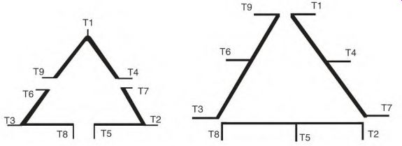
FIGURE 5.35 Comparison of the nine-lead delta schematic with a nine-lead multimode
schematic.
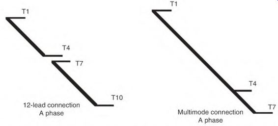
FIGURE 5.36 Comparing the A phase of a 12-lead motor to the A phase of a multimode
motor.
Triple-Mode, Nine-Lead Three-Phase Motor
The triple-mode motor has a lead at the center of each phase. Its data are equal from the center lead to each end of the phase.
Figure 5.37 shows the connections for high, medium, and low torque.
The delta connection (Fig. 5.37a) has the highest torque. Figure 5.37b is the wye-delta connection for medium torque, and Fig. 5.37c is the wye connection for low torque.
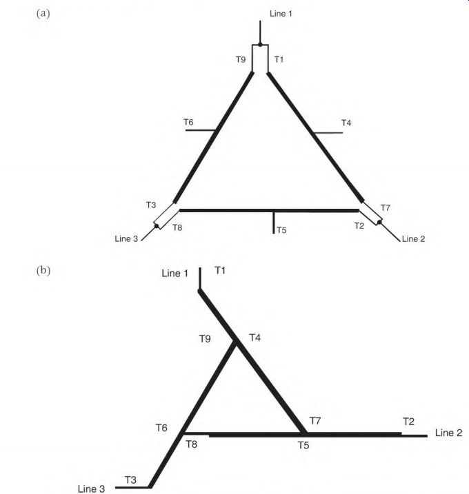
FIGURE 5.37 (a) The delta connection has the highest torque, (b) The wye-
delta connection has medium torque.
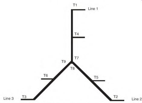
FIGURE 5.37 (continued) (c) The wye connection has the lowest torque.
Identifying the Triple-Mode, Nine-Lead Three-Phase Motor
The triple-mode motor has three separate circuits with three leads each (Fig. 5.37a). The center (of the A phase) lead is T4. Resistance will be the same from T4 to T1 as from T4 to T7. (The same is true of T5 and T6 and their respective leads, T8 and T9.)
Multimode motors have three numbers belonging to one phase (that is, T1, T4, and T7) in each three-lead circuit. The dual-voltage nine-lead delta connection has the numbers of two different phases in each three-lead circuit (that is, T1, T4, and T9).
If there are no lead numbers, find the center lead of one phase and connect the other two leads together. (See "Identifying Unmarked Leads in a Delta Connection" in Section 6.) Apply an intermittent DC voltage to this phase, and check the other two phases for voltage with a low-scale analog voltmeter. There should be little or no deflection. If it is a delta-connected nine-lead motor, the voltmeter will show a strong deflection between two of the three leads in the other circuits.
The multimode motor's nameplate will show three different horsepower ratings and three separate ampere values. There is one RPM value on the nameplate.
Quadruple-Mode, Nine-Lead Three-Phase Motor
The quadruple-mode nine-lead motor is the same as the triple-mode motor except for the location of the center lead. The center lead is located closer to the start of each phase; i.e., the A-phase lead T4 is closer to T1 than to T7.
This gives the motor four torque modes (Fig. 5.38). This motor has one RPM rating and four ampere ratings on its nameplate.
If it's rewound, it is very important to replace the internal connections the same way they were in the original winding.
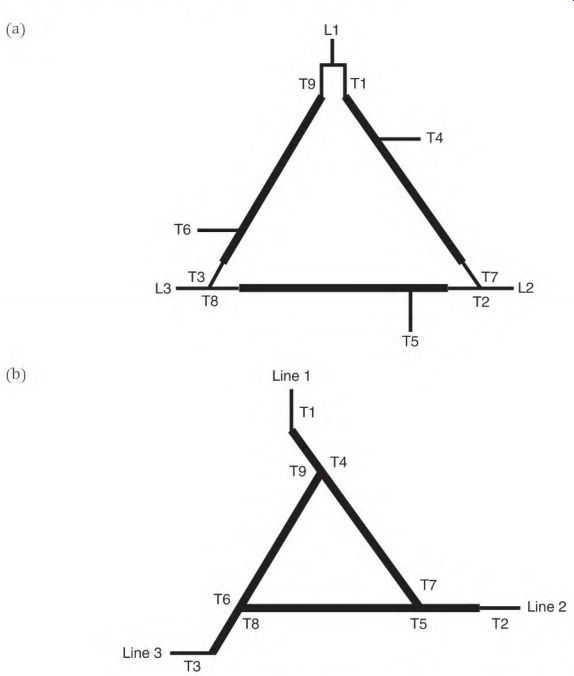
FIGURE 5.38 (a) The quadruple-mode motor schematic connected delta for the
highest torque, (b) The quadruple-mode motor connected delta-wye will have
medium torque.
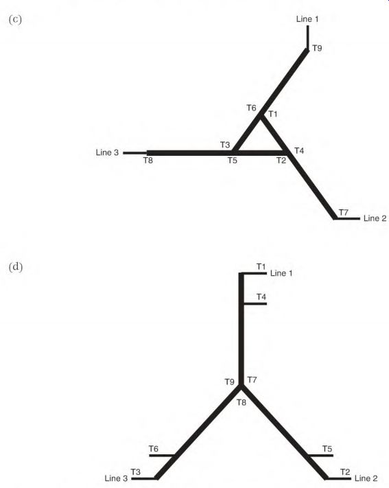
FIGURE 5.38 (continued) (c) The quadruple-mode motor connected wye-delta will
have medium-low torque, (d) The quadruple-mode motor connected wye will have
the lowest torque.
Figure 5.38a shows the delta connection, which has the highest torque.
Figure 5.38b shows the delta-wye connection with medium torque. Figure 5.38c shows the wye-delta connection with medium-low torque. Figure 5.38d shows the wye connection, which has the lowest torque.
Identifying the Quadruple-Mode, Nine-Lead Three-Phase Motor
The same identification logic is used on this motor as described above for the triple-mode motor. The quadruple-mode motor's connection, however, is slightly different from that of the triple-mode motor.
This connection can be identified with an ohmmeter of the right size.
There are three sets of three leads that light to each other. A-phase leads T1 to T4 have much less resistance than T4 to T7. The same is true of T2 to T5, T5 to T8, T3 to T6, and T6 to T9.
Synchronous Motor Synchronous motors are used on loads that need constant speed. These motors range in size from small to many thousands of horsepower.
Figures 5.39 to 5.42 are various pictures of the synchronous motor and its components.
Slip rings DC field; Stator winding
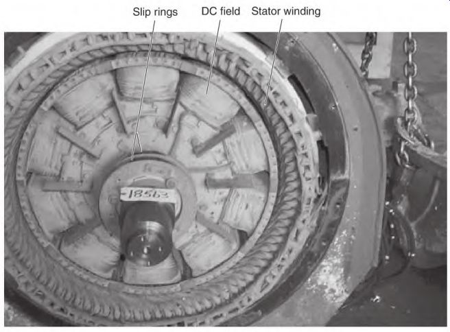
FIGURE 5.39 The synchronous motor. Smith Services.
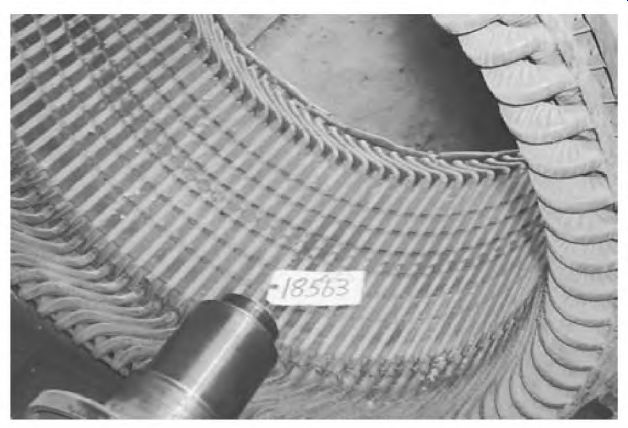
FIGURE 5.40 Stator of a synchronous motor. Smith Services.
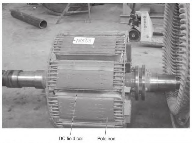
FIGURE 5.41 Rotor of a synchronous motor. Smith Services.
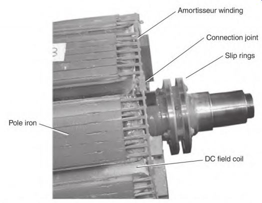
FIGURE 5.42 Amortisseur winding (squirrel cage) embedded in the iron of the
DC poles. Smith Services.
The synchronous motor doesn't have good starting torque and must start with very little load. Common applications are refrigeration compressors and air compressors, because these units can be started with no load and then activated after the motor is up to speed.
The synchronous motor is often used to correct the power factor in industry.
Components of the Synchronous Motor
The synchronous motor has a three-phase stator and frame, as an induction motor or the wound rotor motor (described later) has. The stator winding is either wye or delta connected (or with multiple wyes or deltas) internally.
They are usually connected one voltage. Most operate on high voltage (2400 volts and higher) and have form-wound coils (Fig. 5.40). The rotor of the synchronous motor has DC field poles mounted on it (Fig. 5.41). There are as many poles on the rotor as there are in one phase of the stator. The DC coils get their power from two slip rings mounted on the shaft.
The DC field of the synchronous motor is similar to the shunt field of a DC motor. (The resistance of the coils limits the amperes.) The coils (mounted on the rotor) are well cooled.
The pole iron for the DC poles is laminated, like the stator poles. It's fastened securely to a frame called a spider. The spider is mounted on the motor's shaft.
Each pole has a squirrel cage winding embedded in it above the DC coils (Fig. 5.42). This is called the amortisseur winding. The bars in the pole iron have both ends connected to sections of an end ring. The end ring sections and bars stay with each pole iron piece when the rotor is disassembled.
Additional end ring sections join the pole end ring sections to form a complete circuit. The ring sections are lapped and bolted together securely, both mechanically and electrically. Like any" squirrel cage winding, the circuit has low voltage, and carries very high amperes when starting. When the DC field is energized and the rotor is at synchronous speed, there is no voltage or current in the amortisseur winding.
Operation of the Synchronous Motor
When the stator is energized, the s5mchronous motor starts like an induction motor. The amortisseur winding (like a squirrel cage winding) forms poles that react to the rotating magnetic field of the stator.
The amortisseur winding isn't designed for long-term use (as is the case with the induction motor's squirrel cage winding). It gives the motor adequate torque to start a minimal load. A control energizes the rotor's DC field when the rotor reaches 95 to 98 percent of synchronous speed. The energized DC field quickly pulls the rotor up to synchronous speed. The motor is now ready for loading.
During startup, the lines of force from the stator's rotating magnetic field cut the DC field coils' conductors. At this time, the stator becomes the primary and the DC field becomes the secondary of an extremely high-voltage transformer. The stator coils have very high volts per turn, and very few turns. The DC field coils contain a large number of turns. When transformer theory is applied to this combination, the result is extremely high voltage in the DC field. The DC field coils are connected in series, so the voltage value of each coil adds to the next, resulting in very destructive high voltage at the slip rings.
A discharge resistor is connected across the DC field during startup (to lower the transformed high voltage). The discharge resistor affects the DC field in the same way that an overload affects a transformer. (When a transformer is overloaded, the secondary voltage drops.) The discharge resistor overloads the DC field's transformed voltage, keeping it at a safe value.
For an instant (when the control applies DC voltage to the DC field) DC flows through both the discharge resistor and the DC field. The discharge resistor is then disconnected.
It's very important that the DC field always have either DC power applied to it or the discharge resistor connected across it. A destructively high voltage will develop instantly if the DC field is open. This is one of the main causes of premature insulation failure in DC field coils.
The Synchronous Motor Control
The AC side of the synchronous motor control is similar to most motor controls and doesn't need explaining.
The DC side of the control is shown in Fig. 5.43. The amortisseur winding powers the rotor to 95 to 98 percent of synchronous speed (when AC is applied to the stator of the synchronous motor). As the rotor accelerates, a discharge resistor controls the voltage transformed to the DC field. An AC relay coil (no. 1) is connected across part of the discharge resistor and operates on the voltage drop across this part of the resistor.
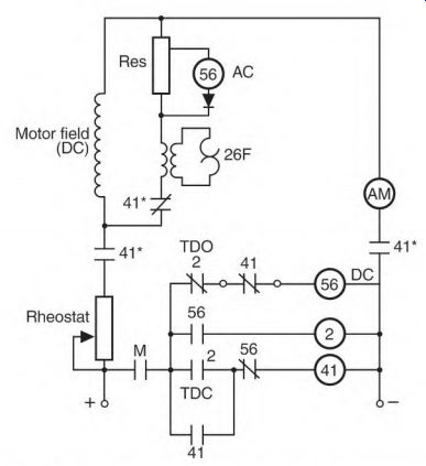
FIGURE 5.43 DC side of a synchronous motor control.
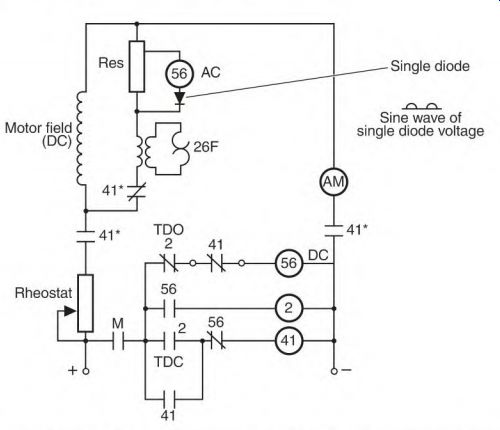
FIGURE 5.44 The single diode allows only half of the sine wave voltage to
energize the control coil. The DC field and resistor are in a closed circuit
during startup.
The voltage transformed to the rotor's DC field during startup is AC. The hertz (cycles per second) of the transformed voltage varies inversely with the rotor's RPM. (See "Amperes and Rotor Bar Design," earlier in the section.) A single diode is in series with coil 56. It will conduct only one-half of the sine wave. The half-wave pulse powers coil 56 (Fig. 5.44). As the rotor approaches 95 to 98 percent of synchronous speed (when DC should be applied), the half-wave pulses are down to about one pulse per second. The time delay between pulses is now so long that the coil can't hold the contacts. But the voltage is always high enough to keep the coil operating. (The time lag between pulses makes the coil release the contacts.) Three sets of contacts are activated when coil 56 drops its load (Fig. 5.45). Two sets (normally open) connect DC power to the field. The third set (normally closed) functions after the other two sets close. For an instant, the resistor and the DC field have DC power applied to them. Then a normally closed contact opens and disconnects the resistor from the circuit.
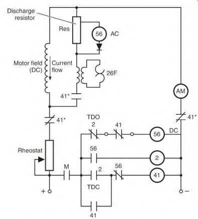
FIGURE 5.45 Current flow when motor is at full speed.
Power Factor Correction with a Synchronous Motor
The synchronous motor can be used to control the power factor of an industry's power supply by increasing or decreasing DC field amperes.
Unlike power factor-correcting capacitors (that correct only power factor), the synchronous motor corrects the power factor and pulls a load. It operates at constant speed. A load can vary from no load to full load (while not affecting the motor's RPM). When no more power is applied to the DC field than it takes to pull the load, the AC power line magnetizes the iron of the AC stator. Magnetizing amperes (furnished by the power line) lower the line's power factor.
(By increasing the amperes in the DC field, the DC field provides the magnetizing amperes.) Increasing DC amperes even more creates the same effect as with a capacitor (the current leads the voltage). Magnetizing amperes (furnished by the synchronous motor's leading current) raise the power factor of the AC supply circuit.
There are synchronous motors (with no shaft) that are used only for power factor correction. They are usually located where power factor correction is most beneficial to the building's circuitry.
The Brushless Synchronous Motor
The brushless synchronous motor operates the same way as the brush type.
The main difference is the way the DC rotor is powered. Eliminating the brushes decreases maintenance of the machine.
The brushless synchronous motor has an AC alternator (or exciter) built into its frame. Instead of brushes carrying power to the DC rotor field, an AC alternator (exciter) furnishes the DC power. The exciter's stator field is DC and is controlled electronically by an external controller (sometimes called the black box). The black box controls the exciter and the output of the rotor components.
The receiver coils on the rotor cut the magnetic lines of force of the exciter's stator field. The power produced by the receiver coil is AC. A rectifier is mounted on the rotor shaft with the receiver coil. Control of the discharge resistor (also mounted on the motor's shaft) and the DC field is achieved with electronic components mounted on the rotor.
Three-Phase Alternator
The synchronous three-phase motor can be used as a three-phase alternator.
The motor is rotated by a power source (diesel, turbine, or an electric motor), and DC is applied to the rotor's DC field. The DC field's flux cuts the stator windings and produces three-phase power.
The voltage (taken from the stator leads) can be varied by adjusting the amperes in the DC field.
Hertz is controlled by the speed of the rotor. If the alternator's power is added to an existing power source, the voltage polarity value and hertz must match those of the existing power source.
The amortisseur (squirrel cage) winding in the three-phase alternator has a dampening effect on speed change (hunting) in the machine when it is lightly loaded.
Wound Rotor Motor
The wound rotor motor is a variable-speed induction motor (Fig. 5.46). It was one of the first variable-speed three-phase motors to be developed. Sizes range from fractional to thousands of horsepower.
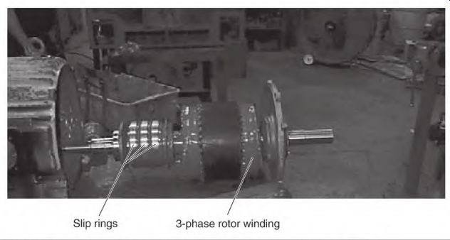
FIGURE 5.46 The wound rotor three-phase motor (disassembled). Smith Services.
Components of the Wound Rotor Motor
The wound rotor motor (Fig. 5.47) has a three-phase stator and frame similar to the induction motor described earlier. The stator winding is wye or delta connected (or with multiple wyes or deltas) (internally) and is usually connected one voltage.
The rotor has a three-phase winding similar to the stator winding (Fig. 5.48). (The pole spacing is identical to the stator pole spacing.) The rotor winding is also wye or delta connected (or with multiple wyes or deltas). Each phase is connected to a slip ring. The rings have brushes riding on them that are connected to leads Ml, M2, and M3. These leads connect to a controller that controls the ampere flow in the rotor windings.
3-phase rotor windings
Slip rings 3-phase rotor winding connected to slip rings
Stator
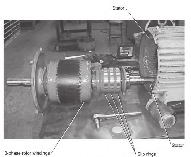
FIGURE 5.47 Stator of a wound rotor motor. Smith Services.
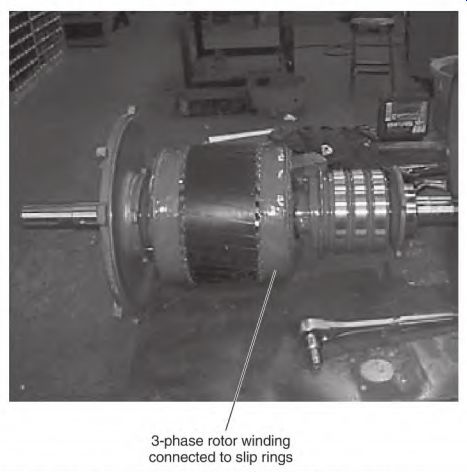
FIGURE 5.48 Rotor of a wound rotor motor. Smith Services.
Operation of the Wound Rotor Motor
Three-phase voltage is transformed into the rotor winding when the stator winding is energized. This creates a three-phase voltage potential across the three slip rings. The voltage value depends on the turn ratio between the rotor winding poles and the stator poles. (Turn ratio is explained under "Transformer Function" in Section 3 and illustrated in Fig. 3.42.) When the motor starts, the rotor control is set at its highest resistance value. The simplest explanation of the control is given in Fig. 5.49. This is a wye-connected set of resistors. (It's very important that resistance be absolutely equal between all three phases.) Figure 5.50 shows a more detailed control with resistors (and contacts that bypass them as more power is needed).
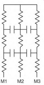
FIGURE 5.49 Control resistors for the wound rotor motor.
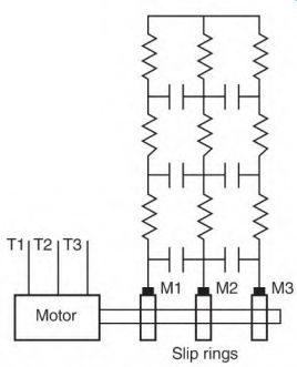
FIGURE 5.50 Wound rotor motor's control, with contacts for bypassing each
resistor.
The control allows a low amount of current to flow in the rotor winding poles when the motor starts. The stator and rotor windings have a good phase angle (see "Phase Angle" earlier in the section) and good starting torque with low current. As the rotor accelerates, the controller decreases its resistance until the rotor reaches full speed. At full speed, the slip rings are shorted together, and the rotor operates as a squirrel cage rotor.
If resistance is cut out too fast, the rotor windings develop high current and high inductance. (Inductance delays the time that current flows.) When peak magnetic power is reached in the rotor poles, the stator pole's magnetic power has already peaked and is dropping to a lower value. The rotor pole's peak power is now out of step with the stator pole's peak power-a bad phase angle. The result is torque loss. The motor will still bring the load up to speed, but the result is excessive heating and needless power loss.
Even on the lowest speed setting, a wound rotor motor will accelerate to near synchronous speed if there is no load. From zero to full RPM, the control and the load regulate a rotor's speed.
Until the motor reaches full speed (when the slip rings are shorted), the motor has low efficiency. To increase efficiency, the power (that is normally wasted as heat with resistors) can be converted to three-phase power, with a regenerative electronic control. This power is returned to the line, lowering the motor's operating cost.
Liquid Used for Speed Control
Another type of rotor current control uses liquid as its resistance. Three plates (connected to the slip ring leads) are lowered into a liquid. Current flow increases as the plates are lowered. The current control is much smoother than one with resistors and contacts.
Reversing the Wound Rotor Motor
Interchanging any two stator leads reverses the wound rotor motor.
Interchanging the rotor leads won't reverse this motor, because the stator poles determine the polarity of the rotor poles.
The wound rotor motor should not be plugged (reversed) while running.
Plugging transforms a very high voltage into the rotor winding. Voltage produced (Try plugging) in the wound rotor winding is too high for the circuit's insulation.
The highest voltage will be at the end of the phases (leads). (The rotor circuit's weakest insulation is between the exposed metal of the slip rings and the shaft.) If one slip ring is grounded to the shaft, the insulation thickness between the rings is cut in half. Arcing will occur between one or both of the other two slip rings and the shaft. Brush dust contamination (in the slip ring area) increases the chances of an arc forming.
Plugging has resulted in rotor winding leads being blown off the slip rings. Voltage dramatically increases in the rotor winding, and has caused a flashover between the slip rings.
Wound Rotor Motor Used as a Variable-Voltage Transformer
A wound rotor can be used as a three-phase variable-voltage source. A geared device controls the movement of the motor's shaft. The stator winding acts as the primary of the transformer, and the rotor winding is the secondary.
The slip rings aren't used.
When the rotor is moved, the voltage transformed into the rotor poles varies as their alignment with the stator poles changes. Total pole-to-pole alignment produces full voltage output. When the rotor poles are moved 90 electrical degrees out of alignment (one-half pole), the voltage output is at its lowest value.
The device that controls the rotor's movement has to be strong enough to withstand the motor's full torque. Torque develops when amperes flow in the rotor windings. The rotor windings are usually redesigned and rewound to produce the desired voltage.
Wound Rotor Motor Used as a Hertz Changer
Before the development of electronic hertz controls, a specially modified wound rotor motor was used to produce 120-Hz power. The power was achieved by energizing the wound rotor motor's stator and driving its shaft against its rotation with another motor. The power was tapped off the slip rings of the wound rotor motor. The quality of power produced by this method is better than today's electronically produced 120-Hz power.
The Brushless DC Motor
The brushless DC motor is a type of three-phase synchronous motor (Fig. 5.51) with permanent magnets on its rotor. (Most synchronous motors have coils on their rotors, powered by DC.) Like the synchronous motor, the brushless DC motor has absolute speed regulation. The speed control is exact (±0). Unlike the synchronous motor, this motor doesn't shut down if it's overloaded. When there is an overload, the controller will automatically adjust the hertz to a different RPM. The power range of brushless DC motors is from V,, to 400 horsepower.
They have NEMA standard frame sizes and enclosures, and the controllers operate on either 50- or 60-Hz power sources.
The brushless DC motor control can include dynamic (regenerative) braking to slow a momentum load. It has full-load torque at zero speed, for use as a brake or as a servomotor. Its acceleration and deceleration capabilities are typically 0.05 to 90 seconds, and they are separately adjustable in the controller. It has electronically controlled plugging capability (reversing) at any speed. The motor's current and voltage are electronically limited when the motor is plugged. This decreases high- ampere stress that plugging typically causes in other types of motors.
The brushless DC motor can withstand a 150 percent overload for 1 minute. It's protected with instantaneous trip action when the current exceeds 250 percent.
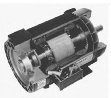
FIGURE 5.51 Cut-away of brushless DC motor. Powertec.
It has nearly unity power factor at all speeds and loads. Magnetizing amperes are limited to the stator. The rotor doesn't require any magnetizing current since the rotor's magnetic field is supplied by a permanent magnet.
(The squirrel cage rotor requires continuous magnetizing.) Components of Brushless DC Motors The brushless DC motor has a three-phase stator winding. The winding is single-voltage and is operated by the motor's controller. It can't operate without its controller.
The rotor has permanent magnets epoxied to its shaft. The magnets are reinforced with several wraps of high-strength fiberglass and epoxy tape.
Hall effect sensors are connected to the motor's end bracket. A multipole magnet wheel is attached to the rotor shaft. The Hall sensor assembly has five to seven wires, which go to the controller in a separate conduit from the stator winding circuit. (The data carried by the control wires would be corrupted if they were in the same conduit as the stator leads.) All brushless DC motors have ball or roller bearings. (It's ve^ important to monitor the condition of the bearings closely.) If a bearing breaks down, the rotor will be destroyed. Bearings in a brushless DC motor last longer than those in most other types of motors (because of the low shaft temperature). Permanent magnets eliminate the heat that results from a squirrel cage's (magnetizing) winding current.
Operation of the Brushless DC Motor
The brushless DC motor operates from a variable-voltage variable-hertz speed controller. A Hall effect sensor (on the motor shaft) tells the controller the exact position of the magnets (relative to the stator poles). The rotating magnetic field is established when the controller alternately powers the stator's three phases. Two phases on and one phase off create a rotating magnetic field.
Three-Phase Servo Motors
Some servo motors operate much the same as the brushless DC motor. They have feedback devices called resolvers, encoders, tachometer generators, and Hall effect sensors, in combinations of two or more.
The servo motor's controller tracks the rotor's permanent magnets. It energizes the proper stator windings to position the shaft exactly as needed.
It can also control the exact speed of the motor.
To determine if a motor has permanent magnets, short two of its leads together and turn the shaft. Permanent magnets will cause resistance to rotation.
If the motor is disassembled, it is very important to put reference marks on the shaft and end bell. Marking the location of components simplifies reassembling.
If the alignment is not recorded, energize two winding leads with low- voltage DC and controlled current (5 amperes or less). This will lock the rotor and provide a reference point for positioning the components. Most servo controls compensate for some misalignment. The number of poles can also be determined this way.
These tiny motors and their controls will probably become throw-away like other small motors.
Identifying the Three-Phase Induction Motor
Three-phase induction motors have many different connections.
Identification can be difficult, especially if there is no nameplate. Most of the connections and their function and application will be identified in this section.
Troubleshooting procedures found in Section 6 can be used on all the motors described in this section.
The number of leads a motor has can help identify its connection. The number can be from 3 to 18 or more. Most are divisible by 3, with the most common being the nine-lead dual-voltage motor.
Six-lead motors have many different variations and can be hard to identify. Wye-delta, constant-torque, constant-horsepower, and variable- torque motors are all six-lead motors (that use the numbers 1 through 6). Connections encountered less frequently are two-speed one-winding, two-speed two-winding, part-winding start, wye-delta, 12-lead motors, dual- voltage multispeed, multimode, and European connections.
A motor with no nameplate presents a common identification problem.
Sometimes a motor has been redesigned to a different horsepower, speed, or voltage (without the change being noted on the nameplate). All motors should be tested using a current-limiting control, such as resistors. An unidentified motor should never have full power applied to it.
Nine-Lead Dual-Voltage Motors
A nine-lead dual-voltage motor will always be wye or delta connected.
The wye-connected nine-lead motor has three sets of two leads that light to each other and one set of three leads that light to each other.
The delta-connected nine-lead motor has three sets of three leads that light to each other. The multimode motor also has three sets of three leads that light to each other. There is, however, a big difference in the motor's internal connections. This is explained under "Multimode Nine-Lead Three- Phase Motors," earlier in the section. (This connection is found mainly in the oil field industry.)
Nine leads make it possible to operate a three-phase motor on either of two voltages. There is a 2-to-1 difference between the high- and low-voltage connections.
Nine-lead motors (both wye and delta) can also be connected part- winding start if they have the right style of winding. This is explained later in this section under "Concentric-Style Winding and Part-Winding Start Connection."
A variation of the nine-lead wye-connected motor involves a tenth lead. The tenth lead is used for joining the internal wye(s) when the wye- connected motor is connected low voltage.
Troubleshooting these motors is covered in Section 6.
Three-Lead Motors
Three-lead three-phase induction motors are designed for one voltage and one speed. (Larger motors usually have three leads, because they are seldom designed for dual voltage.) Nine-lead motors (when rewound) can be changed to three leads if they operate on only one voltage; thus there are fewer connection problems than with nine leads. (The motor's voltage rating should be stamped on the nameplate.) Run the motor on low voltage (240 volts) with a current-limiting control if the voltage isn't known. If it starts with much less inrush current than expected, it's connected or designed for a higher voltage. The motor will have about one-fourth of its normal power and will start more slowly than normal.
It's hard to determine the right voltage for small motors. They' start quickly on low voltage-although connected for high voltage-because of their lightweight rotors. No-load amperes will be extremely low when run on low voltage.
The three-lead motor's internal connection will be wye or delta. Both are tested with the same testing procedures found in Section 6.
Six-Lead Motors
When a motor has six leads, it can have many different connections. (Some examples are constant-torque, constant-horsepower, variable-torque, two- speed two-winding, part-winding start, and wye-delta connections.)
Six leads are sometimes used on single-speed induction motors, because there isn't room between the motor's core and shell for three larger leads. In this case, the leads of each phase should be secured in one lug so they stay together.
The data on the nameplate help to identify the six-lead motor's connection. The number of circuits between leads is also helpful. The motor's nameplate should have the horsepower, speed, and voltage. This information may be all that is needed to identify the motor's connection. If the nameplate doesn't give enough information, check the number of circuits between the leads. Circuit descriptions (in the following text) can then be used for identification.
A two-speed one-winding motor will have six leads that all show continuity to each other. They are numbered 1 through 6. Their nameplate will show different horsepower ratings (related to its design) but seldom will identify the motor's type. They all have a 2-to-1 speed rating and are oversized (for their horsepower). Constant-torque motors have two horsepower ratings. (The high speed has twice as many horsepower as the low speed.) A constant-horsepower motor has the same horsepower rating for both speeds. Variable-torque motors have two horsepower ratings. (The low-speed horsepower is one-fourth that of the high-speed horsepower.) The three connection schematics shown in Fig. 5.52 identify the types of connection used in these motors. (The constant-torque motor is the most common.)
Constant-Torque Connection
Connect the lead numbers (as shown on the constant-torque schematic for low speed) with T4, T5, and T6 open, and apply limited-current three- phase power. If the motor runs well, connect it high speed. If it operates satisfactorily, run the motor with full rated voltage on both speeds.
Connected low speed, the motor may draw full or slightly above nameplate amperes. Connected high speed, it should draw approximately 50 percent less than the nameplate amperes, which would indicate that the motor is connected constant torque. This (constant-torque) motor has twice the horsepower on high speed that it has on low speed.
Variable-Torque Connection
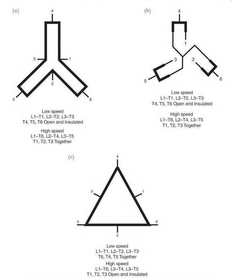
FIGURE 5.52 (a) The constant-torque connection, (b) The variable-torque connection,
(c) The constant-horsepower connection.
Variable-torque and constant-torque motors use the same lead number combinations. If the motor's power is especially low (on low speed), the motor's connection is variable torque (Fig. 5.52b). The variable- torque motor's low-speed horsepower is one-fourth that of its high-speed horsepower. Load testing the motor is an easy way to tell the difference between the two connections.
Constant-Horsepower Connection
If the motor is designed to be constant horsepower (Fig. 5.52c), the low- speed constant-torque connection will cause it to draw very high amperes.
If amperes are high, test the motor (with limited power) using the constant- horsepower connections.
If the motor connection has been positively identified and has very little power, it is connected (or redesigned) for higher voltage than is being applied. Test the motor (first, with limited power) using a higher voltage.
Two-Speed Two-Winding Connection
The two-speed two-winding motor has two sets of three leads that light to each other. The lead numbers are T1, T2, and T3 for low speed; T11, T12, and T13 for high speed. There may or may not be two horsepower ratings on its nameplate. If so, the low-speed horsepower will be less than that of the high speed.
The two-speed two-winding motor has the same number of circuits (two sets of three) as the part-winding start motor (to be covered next). Part-Winding Start Connection The part-winding start motor will have two circuits of three leads. One circuit is numbered T1, T2, and T3; the other, T7, T8, and T9. Each circuit contains a portion of a single-speed winding.
The most common connection is the half-winding start, using the two- wye connection. (One-half of the winding is in each circuit.) Applying limited three-phase current to one circuit will identify this connection. If the motor starts and runs, do the same test with the other circuit. Both circuits should run at the same speed and amperes. The motor's power is roughly one-half with one circuit.
The motor may or may not be noisy (depending on the internal pole-to- pole connection), and the amperes will be low. Connect line 1 to T1 and T7, line 2 to T2 and T8, and line 3 to T3 and T9. The motor should start and run with full power. (The motor starts the load on one-half of its winding. After 2 or 3 seconds, the other half is energized.)
The inrush amperes are one-half the amps of across-the-line starting (using the complete winding). As the speed increases, the amperes in the first-stage winding drop. When the second-stage winding is energized, its ampere demand will be about the same as that of the first stage. With both stages energized, the total ampere demand is less than that of across-the-line start.
Part-winding starting is not recommended for a load that demands frequent or heavy prolonged starts. (Excessive heat will develop in the first-stage winding because it has full voltage applied to it.) If heat doesn't have time to dissipate (from frequent starts), the winding's insulation life is reduced. The wye-delta start method (discussed later in this section) is better for heavy, prolonged starting.
Part-Winding Start of a Two-Pole Motor
Two pole motors can be part-winding started if they have the right internal connection. If T1, T2, and T3 are connected to the first pole of each phase, as illustrated in Fig. 5.53, the motor will start and run normally (when T7, T8, and T9 are energized). If T3 is connected to a pole in the other half of the winding, the motor may reverse itself when the second half is energized.
Concentric-Style Winding and Part-Winding Start Connection
The nine-lead motor (with a concentric-style winding) won't start on part of its winding. This problem occurs often when a lap wound motor, or a specialty connected part-winding start motor, is replaced with a standard (concentric-wound) motor. A special connection (not used on standard nine- lead dual-voltage motors) has to be used.
Internal connection
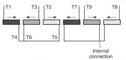
FIGURE 5.53 The internal connections for a two-pole motor that will work with
a part-winding start control. The motor won't reverse when the second half
is energized.
To keep up with competition and high-volume demand, most motor manufacturers use the concentric winding method. Concentric-shaped coils can be inserted into a motor's slots with a machine. (The lap winding has to be wound by hand.) Electric motor repair centers often redesign the concentric winding to lap winding.
Wye-Delta Connection
The wye-delta connection (Fig. 5.54) is used in Europe as a dual-voltage connection. In the United States, the connection is used primarily as a starting method.
A motor connected wye-delta will have three sets of two leads that light to each other (T1 to T4, T2 to T5, and T3 to T6). There will be two voltage ratings on the nameplate, with the higher voltage (wye) being 1.73 (the square root of 3) times the lower voltage (delta). The operating voltage (for wye-delta starting) is that of the delta connection. If the delta connection is rated 220 volts, the wye connection voltage will be 380 volts (a difference of 160 volts). To produce full power, the volts per turn must be the same for both connections.
Verify the connection by connecting T4, T5, and T6 together; then apply limited three-phase current to T1, T2, and T3. (Use the voltage rated for the delta connection.) The motor should start slowly and have reduced power.
Reconnect the motor (using the delta connection: line 1 connected to T1 and T6, line 2 to T2 and T4, line 3 to T3 and T5). If the voltage and connection are correct, the motor should run normally with full load.
Wye-Start, Delta-Run Starting Method
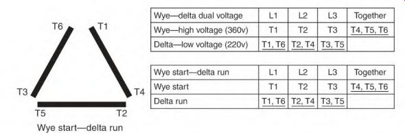
FIGURE 5.54 The wye-delta connection.
The wye-start, delta-run method of starting is similar to reduced-voltage starting. The wye connection is energized first with 220 volts (the delta operating voltage). A few seconds later the control switches to the delta connection, and the motor runs at full power.
Using this method, the inrush amperes are much less than with across- the-line starting. This allows the motor to take more time to start a heavy load, without excessively overheating its winding.
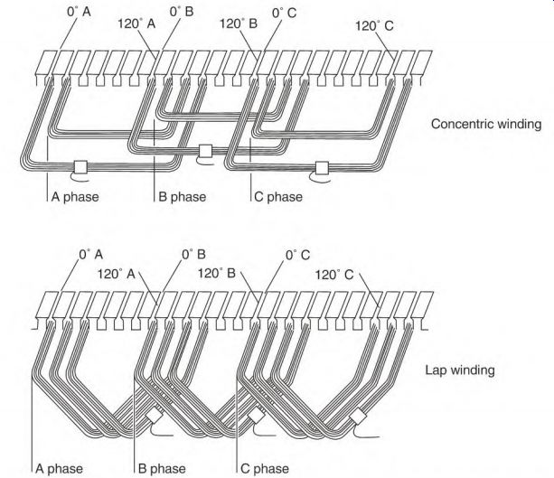
FIGURE 5.55 Two shapes (concentric and lap) used in mush-wound motor windings.
The motor will have approximately one-third of its normal torque on the wye connection. The load must not require a breakaway torque higher than the wye connection can produce.
If a wye-delta-connected motor doesn't have enough breakaway torque, the one-delta start, two-wye run connection can be used. (The operating voltage must be for two wye.) The one-delta start, two-wye run connection (explained a bit later under "Twelve-Lead Single-Speed Motors") produces 40 percent more starting torque than the wye-delta method. Inrush amperes are higher than those of the wye-start, delta-run method.
Wye-Delta Induction Motor with Unknown Voltage
Sometimes a motor's nameplate is missing or doesn't show a voltage rating.
If the coils are mush-wound lap or concentric, the motor's voltage may be rated anywhere from 208 to 760 volts (Fig. 5.55). (The mush winding is rarely used on voltage above 760 volts.) The coil wire is usually visible with the mush winding.
Form-wound coils are used in motors above 2400 volts. This type of winding is rarely found in motors rated 760 volts and less. The coils are each wrapped with insulation. A motor repair center or the motor's manufacturer should be consulted to determine the correct voltage.
Applying a voltage that is too high (for example, 460 volts to a 230-volt motor) will destroy a motor in a few seconds. Always use limited current (resistors) when the voltage is unknown.
When the voltage is uncertain and the motor has no electrical problems, the following procedures should be followed:
1. Connect it wye and run it without a load, with limited current.
2. If the motor starts slowly and draws very few amperes, then the voltage is too low or the delta connection should be used.
3. Connect the motor delta and apply the same voltage (using limited current). The motor will start more quickly and draw more amperes than with the wye connection.
4. Apply full voltage while watching the way it starts, and the no-load amperes.
5.
6.
7.
8.
9.
If it starts slowly and amperes are low, apply the next-higher voltage, using the same procedure (wye connection first), until the motor starts and runs normally.
Load the motor and check the amperes.
Assuming the amperes aren't excessively high, use a tachometer to see if the RPM is satisfactory. (Motors above 50 horsepower will have less slip than motors under 50 horsepower.) Divide 7200 by the number of poles to get the motor's synchronous speed (explained in Section 3 under "Revolutions per Minute, Poles, and Hertz"). Slip should be less than 1 percent unless the motor is designed for high slip (5 percent slip is maximum for high-slip motors). If slip is excessive with the wye connection, connect the motor delta and run it with limited current and no load.
If amperes aren't excessively high, apply full voltage and full load and check the RPM. A motor-connected wye using the delta voltage will start and run almost normally. With the motor fully loaded, however, the slip will be excessive, the windings will overheat, and the motor will fail in a few hours.
Twelve-Lead Single-Speed Motors
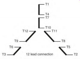
FIGURE 5.56 The 12-lead numbering sequence used in the United States.
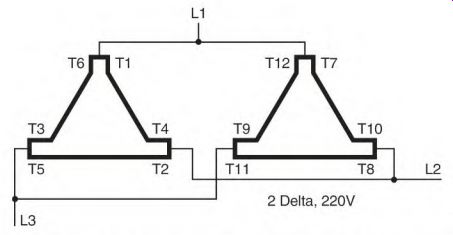
FIGURE 5.57 The lowest voltage connection for the 12-lead motor is two delta.
The 12-lead connection (numbered 1 through 12) will have six pairs of leads that light to each other. Figure 5.56 shows the connection. The difference between this connection and the nine-lead connection is that the end of each phase (T10, T11, and T12) is accessible in the motor's connection box.
The 12-lead motor can be connected to four different voltages: wye-delta, one-delta start, two-wye run, and variations of part-winding start methods.
Figure 5.57 is the two-delta connection, which has the lowest voltage rating. Regardless of what the two-delta connection voltage rating is, the voltage rating of the two-wye connection is 1.73 (square root of 3) times that voltage (Fig. 5.58). In this case, if the two-delta connection is rated 220 volts, 220 x 1.73 = 380. The two-wye connection is rated 380 volts.
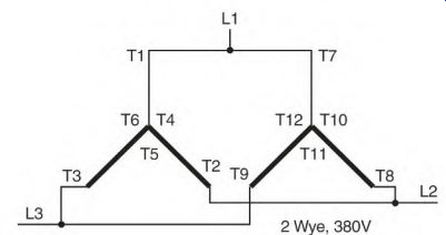
FIGURE 5.58 The voltage rating for the two-wye connection is 1.73 times the
two-delta connection.
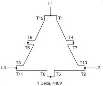
FIGURE 5.59 The voltage rating for the one-delta connection is twice that
of the two-delta connection.
If a two-delta (parallel) connection is rated 220 volts, a one-delta (series- connected) is rated 440 volts (Fig. 5.59).
If a two-wye (parallel) connection is rated 380 volts, a one-wye (series- connected) is rated 760 volts (Fig. 5.60).
The 12-lead connection can be used as a part-winding start on two voltages. It can be connected two wye to start and two delta for ran (operating on the two-delta voltage). It can also be connected one-wye start and one-delta ran (operating on the one-delta voltage). Another start method (made possible by the 12-lead connection) is one- delta start and two-wye run. This connection will produce 40 percent more starting torque than the wye-start, delta-run connection. (The increased starting torque will require higher inrush amperes.)
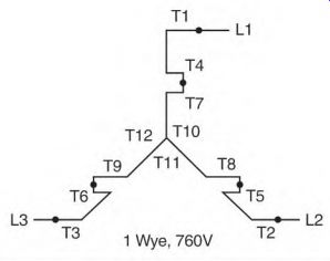
FIGURE 5.60 The voltage rating for the one-wye connection is twice that of
the two-wye connection.
The operating voltage must be that of the two-wye connection and may require rewinding the motor for this voltage.
Dual-Voltage Multispeed Motors
The dual-voltage connection is rarely encountered in two-speed motors. As shown in the following schematics, dual-voltage two-speed motors require 18 leads. The schematics in Figs. 5.61, 5.62, and 5.63 (a and b) are constant- torque, constant-horsepower, and variable-torque dual-voltage connections, respectively.
The two-speed dual-voltage-connected winding can't be used with another winding. There are many closed-loop parallel circuits with the two- speed dual-voltage motor connected low voltage (5.63b). All the closed-loop circuits have to be opened when this winding is idle.
European Connections
The International Electrotechnical Commission (IEC) labeling system is used in Europe and Great Britain. Figures 5.64 and 5.65 show this labeling system.
Much of the equipment brought into the United States from Europe and Great Britain has motors with this lead numbering system.
Figures 5.66 and 5.67 show the former European connections for the wye-delta and 12-lead motors. Figures 5.68 and 5.69 give the former Great Britain connections for the wye-delta and 12-lead motors.
Most of these motors are designed to operate on 50 Hz. The horsepower ratings are usually given in kilowatts. (Conversion to 60 Hz was explained earlier in this section, under "Operation of the Three-Phase Motor.") two-wye connection.
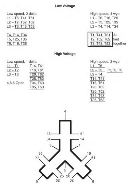
FIGURE 5.61 Dual-voltage constant-torque connection.
European frame sizes are metric. If they are replaced with NEMA frame sizes, an adapter plate can be used.
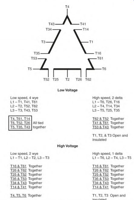
FIGURE 5.62 Dual-voltage constant-horsepower connection.
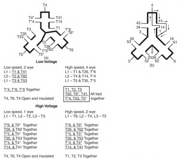
FIGURE 5.63 (a) Dual-voltage variable-torque connection, (b) Circulating current
(arrows) if connection isn't open when used with another winding.
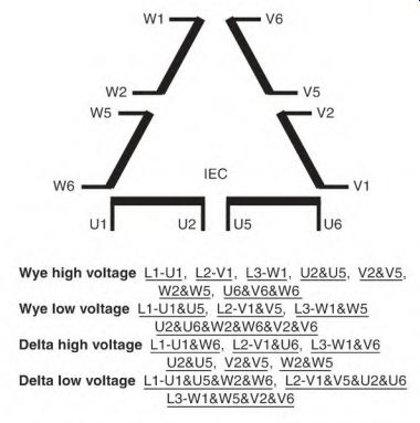
FIGURE 5.65 The IEC 12-Iead numbering system for Europe and Great Britain.
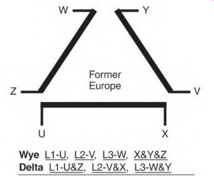
FIGURE 5.66 The Former wye- delta connection for Europe.
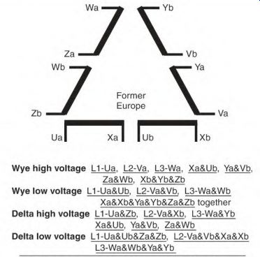
FIGURE 5.67 The former 12-Iead connection for Europe.
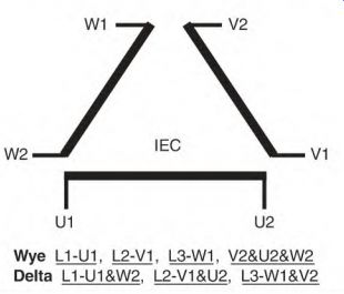
FIGURE 5.64 The latest version of the wye-delta connection, developed by the
IEC in Europe and Great Britain.
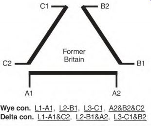
FIGURE 5.68 The former wye-delta connection for Great Britain.
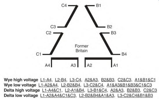
FIGURE 5.69 The former 12-lead connection for Great Britain.
The European connection system can be replaced with the simpler numbering system found in the United States. The internal connections are identical to those of U.S. motors.
Section 5 Review
1. What qualities make the three-phase induction motor popular for industry (01)?
2. The speed of a three-phase induction motor is governed by the number of poles, the Hz of the power source, and the load (01). T F
3. The laminations in a 25-Hz motor core are thicker than those in a 60-Hz motor (203-204). T F
4. A motor with a short body is a good choice for vibrating loads (04). T F
5. The three phases of a three-phase motor are separated from each other by electrical degrees (05).
6. Rotating torque occurs because of time that peak power develops in each phase matches the degrees of physical separation of the phases (206-208). T F
7. Single-phase voltage will not start a three-phase motor (09). T F
8. A three-phase motor running on single phase will have about of its rated horsepower (209-210).
a. V3
b. 72
c. 7,4
9. An induction motor draws high amperes when it starts because of the high current demand of the squirrel cage rotor (10). T F
10. High (starting) amperes mean high torque (10). T F
11. The code letter is used to determine a motor's full-load amperes (13). T F
12. A motor's torque value is constant as the RPM change (213-214). T F
13. A load has torque, RPM, and horsepower requirements, whereas a motor needs only the horsepower rating that the load demands (14). T F
14. Nameplate RPM (full-load RPM) is the speed at which a motor has the most torque (14). T F
15. The design letter helps fit a motor to its load requirements (14). T F
16. The design A motor is used when nearly constant-load RPM is required (214-215). T F
17. The design B motor is popular because it meets most load requirements, and doesn't require high starting current (15). T F
18. The design C motor has higher torque characteristics than the design B motor (215-216). T F
19. The design D motor draws low starting amperes and has high starting torque, but has low torque at full RPM (16). T F
20. The design D motor can handle intermittent overloads that would overheat design B or C motors (16). T F
21. All induction motors operate at exactly nameplate RPM (216-217). T F
22. A wye-connected motor has four circuits, and the delta-connected motor has three circuits (17). T F
23. The nine-lead delta connection has one circuit of three leads and three circuits of two leads (217-218). T F
24. A telephone keypad can be used to identify numbers on the 9-, 10-, and 12-lead connections (218-219). T F
25. The 12-lead connection has four voltage connections, and more starting options than the 9-lead connection (224-227). T F
26. The 12-lead connection can be used for part-winding start and other start methods (25). T F
27. Multispeed motors all have one winding (27). T F
28. Name three types of one-winding two-speed motors (227-228).
29. A two-speed one-winding motor, with no load, draws less current on low speed than it does on high speed (228-230). T F
30. A constant-horsepower motor has high torque on low speed (228-229). T F
31. A constant-torque motor has more horsepower on speed (29).
a. low
b. high 32. A variable-torque motor has a horsepower rating similar to a constant- torque motor (229-230). T F
33. Two-speed two-winding motors have no internal connection between the windings (230-231). T F
34. The multimode motors' main feature is to save energy cost during low loading for prolonged periods of time (31). T F
35. The multimode motor is used because it has a good power factor, and because its power can be adjusted to different load requirements (31). T F
36. The multimode motor is seldom found outside the oil industry, but would work well on an air compressor application (31). T F
37. The nine-lead motor that can be confused with the multimode motor when testing for the number of circuits is (32)
a. wye.
b. delta.
38. The difference between a triple-mode motor and a quadruple-mode motor is the location of the center lead in each phase (233-237). T F
39. The DC field on a synchronous motor is used only for starting the load (40). T F
40. The amortisseur winding is a squirrel cage winding (40). T F
41. A discharge resistor is used to limit the DC field amperes (40). T F
42. High amperes are the main cause of DC field failure (240-241). T F
43. allows the field control relay to energize the DC field (240-241).
a. Lowered voltage
b. Low Hz
44. Overexciting the DC field changes the synchronous motor's RPM (241-242). T F
45. The synchronous motor (used to improve an industry's power factor) has to be loaded (243-244). T F
46. The brushless synchronous motor operates the same as the brush type (243-244). T F
47. The synchronous three-phase motor can he converted to an alternator that produces three-phase power (44). T F
48. The control that was formerly used to improve power factor on a synchronous motor is used to control the Hz in an alternator (44). T F
49. The amortisseur (squirrel cage) winding becomes a damper winding in an alternator (44). T F
50. The wound rotor motor is an induction motor (244-245). T F
51. The three-phase winding (and controller) on the rotor of a wound rotor motor controls the motor's torque (245-247). T F
52. Lowering the rotor amps lowers the stator amps (247-248). T F
53. Eliminating resistance in the rotor control too fast stresses the motor's windings (247-248). T F
54. The wound rotor control precisely regulates the motor's speed even if there is no load (48). T F
55. The wound rotor motor can be reversed by interchanging its leads (48).
a. rotor
b. stator
56. A wound rotor motor can be used as a variable-voltage transformer or as a Hz control (49). T F
57. A brushless DC motor runs at synchronous speed (249-250). T F
58. Servo motors are a miniature brushless DC motor (251-252). T F
59. An unidentified nine-lead dual-voltage motor may be connected wye, delta, or multimode (52). T F
60. An unidentified three-lead three-phase motor should be test run with low voltage and limited current before trying a higher voltage (53). T F
61. Six-lead motors are the hardest to identify (253-254). T F
62. Name the three types of one-winding two-speed motors (54-256).
63. It isn't advisable to first test run an unidentified motor with full voltage (53). T F
64. Higher lead numbers indicate a higher speed winding in a two-winding two-speed motor (56). T F
65. The main purpose of the part-winding start is to reduce the starting amps (256-257). T F
66. A two-pole motor may not start using the part-winding start method (57). T F
67. The standard concentric-wound motor may not start with half its winding (257-258). T F
68. A wye-delta-connected motor has two circuits with three leads (58). T F
69. The wye-delta start method allows more time to start a load without overheating the winding (258-259). T F
70. Once the connection and voltage are identified, the tachometer should be the final test instrument used (at full load) (259-260). T F
71. In the standard 12-lead motor, lead T10 is the end of the A phase, T11 is the end of the C phase, and T12 is the end of the B phase (261-262). T F
72. The 12-lead motor can be used for part-winding start (62). T F
73. Dual-voltage two-speed motors need 18 leads (63). T F
74. The European connection system can't be converted to the U.S. number system without altering the internal connections (63). T F