AMAZON multi-meters discounts AMAZON oscilloscope discounts
Troubleshooting Logic Using Voltage Rules
Many electrical problems can be explained using the logic in these three rules:
1. When a conductor cuts or is cut by magnetic lines of force, a voltage is created in the conductor.
2. The voltage value increases as the speed of cutting lines of force increases. An example is the speed of a generator's armature.
3. The voltage value increases with an increase in the number of lines of force.
Example: Increasing the excitation amperes in the shunt field of a DC generator, or the rotor windings of an AC alternator, will increase the voltage value.
The speed at which lines of force cut conductors can be very high when AC or DC is switched off. The arc that forms when the load-carrying contacts open is destructive to the contacts, but the effect of the arc is to slow the shutdown of power. When the shunt field of a DC machine is shut off, the magnetic field from thousands of turns of wire will collapse. As the magnetic field collapses, its lines of force cut the shunt field's turns, producing a very high voltage. If this shutdown is instantaneous (as done with electronic switching), the result is an extremely high voltage spike.
Any sudden voltage change from full voltage to zero or to another voltage will cause the amperes and the resulting magnetic field around conductors to change at the same rate. Any conductor within this magnetic field will have voltage transformed into it. The result can be a very destructive spike that arcs through insulation, and can also destroy electronic circuitry. The voltage spike value increases as the length of the conductors increases. If the distance between an electronic speed controller and the motor it controls is over 50 feet, spike damage to the motor's winding is common. Spike-caused insulation breakdown will occur within the first few turns of a motor's line lead. Spike voltage can be dampened with reactors-a coil of heavily insulated wire wound around laminated iron. A reactor bucks sudden power changes.
Power lines in Canada that feed the eastern United States have problems with magnetic storms from the sun. Although the magnetic field is barely detectable, the voltage becomes very high and destructive when accumulating over hundreds of miles. These storms have moved magnetic North so far that survey crews have had to adjust for it.
Steel conduit that gets hot is another problem caused by magnetism. A conduit containing multiple, unevenly loaded conductors gets hot from eddy current. Eddy current circulates in steel when magnetic lines of force cut this ferrous metal. (This heat is a direct power loss.) If the amperes are the same in each conductor, their magnetic fields cancel each other and reduce the heating effect.
A neutral wire or a bare equipment ground wire can become dangerously energized by being located close to the magnetic fields of other wires. An equipment ground wire (that doesn't go back to the transformer) can be ineffective if connected to a ground rod that doesn't carry enough amperes.
In the case of dry sand conditions, it would be safer to use an ungrounded power supply. (Poorly designed electrical systems in desert locations can be deadly where plumbing is involved.)
Troubleshooting Less Common Motors
Troubleshooting Identified Motors
The troubleshooting procedures under "Typical Winding Problems" in Section 6 can be used on all types of three-phase motors.
The motor's connection first must be identified. The schematic of the motor then is used to test equal circuits and, if necessary, to locate the problem. Comparison testing is the most accurate and dependable test procedure.
All circuits should be given the proper winding-to-frame test (with the usual precautions), starting with an ohmmeter.
Power supply problems (unbalanced voltage, low or high voltage, spikes, etc.) are all in-plant problems that cause motor failure. These problems don't cause immediate motor failure so they are often overlooked.
Bearing breakdown is high on the motor failure list. Information is found under "Bearing Maintenance," later in this section.
Keeping good records on special motors can shorten troubleshooting time. Some motors and controls need more attention than others. Odd characteristics of a motor, such as high amperes of the multispeed consequent-pole motor's low-speed connection, should be noted in the motor's maintenance record. Control contacts that deteriorate sooner than normal should also be noted, as well as solutions to past problems. Having easy access to this type of information can shorten (or prevent) downtime.
Special motors such as multispeed or special-frame motors are expensive and hard to replace. (They usually have to be rewound or repaired.) Special-duty motors often have copper or other alloys (other than aluminum) in their rotors. Broken rotor bars occur much more often with these alloys than with cast aluminum. Symptoms of broken rotor bars are found in Section 3, "Broken Rotor Bars." Troubleshooting the Synchronous Motor The brush-type synchronous motor components most likely to break down are
• The DC exciter fields and discharge resistor
• The amortisseur (squirrel cage) winding
• The stator winding
• Bearings
The brushes, brush holders, and slip rings can have extremely high voltage while the motor is operating. Use caution with these components.
The DC Exciter Field and Discharge Resistor
The DC exciter field and its discharge resistor are a closed circuit (Fig. 7.1)
until the motor control energizes the DC field and then disconnects the discharge resistor.
When the motor starts, the DC field will have high voltage transformed into it. The transformed voltage is controlled by the overloading effect of the discharge resistor. If the resistor develops a faulty connection, it won't load the field circuit enough and voltage will become too high. The DC field may not fail immediately, but its insulation has been stressed and will eventually break down. Most DC field failure is related to high-voltage stress.
A shorted DC field coil may keep the machine from reaching a speed high enough (95 to 98 percent of synchronous speed) to apply the DC voltage. If too many turns are shorted out, a circulating current develops and forms a pole in the coil's iron. This pole will buck the pole formed by the amortisseur (squirrel cage) winding, causing loss of starting torque, and the motor won't be able to get up to speed.
FIGURE 7.1 The function sequence of the contacts 41°. Normally closed contact
41° opens after normally open contacts (also 41°) close.
For the first test, visually check each coil for signs of shorted coils. (The coils are usually wrapped and varnished, making it hard to see signs of a short.) The DC exciter field can be tested with the same procedures that are used on the shunt field of a DC motor. (The resistance of the field coils controls the current.) The coils can be comparison-tested using the motor's DC source and a voltmeter (voltage drop test) or by using an ohmmeter. The current should be limited with resistors to about one-half of the field's ampere rating.
For the DC voltage drop test, divide the applied voltage by the number of coils-to get the approximate voltage drop across each coil. The voltage read across the coils should be + 5 percent of each other.
An ohmmeter or micro-ohmmeter can also be used to compare the resistance of the coils. The allowable difference is + 2 percent.
The discharge resistor limits the transformed voltage in the DC field each time the motor starts. Its purpose is to overload the circuit and cause a voltage drop, the same as an overload affects the secondary of a transformer.
The resistors are usually made of ni-chrome wire, which expands and contracts each time the motor starts. If it is adjustable, the movable contact (clamped to it) may loosen. The discharge resistor, its control, and all connections in the circuit should be checked at least once a year.
Connections can be checked with an infrared gun (as the motor starts). If a coil is shorted, the rest of the coils in its (series) circuit may be damaged. They" should be individually surge-tested for turn-to-turn insulation damage.
The DC field circuit's resistance to ground should be tested yearly with an ohmmeter and a megohmmeter. Early detection of insulation leakage from brush dust or other conducting contaminants will avoid a catastrophic breakdown.
The Amortisseur Winding
The amortisseur (squirrel cage) winding is designed to bring the rotor up to 95 to 98 percent of synchronous speed. At this time DC is applied, bringing the rotor up to synchronous speed.
The amortisseur winding is not designed for continuous duty. Each time the motor starts, the amortisseur winding expands and contracts. This will eventually cause the bars to crack and become open. Open bars cause a loss of torque, and the rotor can't get up enough speed to complete the start cycle. (See "Assorted Rotor Problems" in Section 6.)
The amortisseur winding can be checked with an infrared gun (if the motor has an open frame). Start the motor and run it long enough to heat the amortisseur winding. Check the bars and end ring connections immediately. A bar that is cooler than the rest is open. An end ring connection that is hotter than the rest has a bad connection.
Stator Winding
The stator winding is connected in the same way as any three-phase stator.
It will be connected either wye or delta-usually multiple wyes or deltas. It's subject to the same problems explained in Section 6.
Large synchronous motors are form-wound, with each coil wrapped individually. They are designed to operate on high voltage.
The same test procedures are used on both large and small motors.
Instruments for testing them include an ohmmeter, a megohmmeter, a micro-ohmmeter, and a surge tester.
The first test should be done with an ohmmeter, from a lead to the frame of the motor. A low reading (less than 50 megohms) indicates that conducting contaminants may be on the windings. The megohmmeter can be used next to verify the ohmmeter readout. Be sure to ground a lead to the frame after the megohmmeter test.
The comparison test for shorted windings can now be done with a micro-ohmmeter at the motor terminals in the control box. (Breakdowns such as shorted coils are usually very visible.) If there is a difference in the readings of the comparison test (compare leads 1 to 2 with 2 to 3, and 3 to 1), use the surge tester to confirm the micro-ohmmeter results.
Corona
High voltage will cause a phenomenon called corona. Corona is the blue light that surrounds the coils while the motor runs. (The air next to an energized winding becomes ionized and glows.) It will also make a hissing or buzzing sound. Like any electrically caused spark, the corona gives off a radio frequency.
A minute amount of damage to the insulation is done each time the corona discharges. It erodes a tiny particle of insulation which-over time-will produce a fine white dust. (This can be minimized by coating the coils with a conducting paint in the area where they contact the slot iron.) Damage occurs slowly-over years in most cases.
More corona damage is caused by the ozone it produces. An arc changes oxygen to ozone gas. This gas attacks insulation by chemically degrading it. Ozone does the greatest damage in voids in the slot, or between turns.
Vacuum/pressure impregnation (V PI) application of varnish will reduce the number of voids. (The varnish must have the right level of viscosity to successfully eliminate voids.)
Bearings
Worn sleeve bearings reduce the air gap on one side of the rotor. The result is extreme mechanical stress to the shaft and bearings. There should be about 35 pounds per square inch of magnetic pull, equally distributed around the rotor (if it is centered). If the air gap is reduced by one-half on one side, the magnetic pull on the wide side will drop to approximately 10 pounds per square inch, while the narrow side will go up to nearly 150 pounds per square inch. Bearing wear is accelerated by the increased stress.
Air gap should be measured yearly on pedestal bearing motors.
Temperature change can cause movement of the supporting components.
(There have been cases of concrete swelling when reinforcement mesh rusts.)
Step Voltage Test
The step voltage test (explained in the Section 8 section, "Instruments for In-depth Testing and Scheduled Maintenance") is a reliable method of testing large synchronous motors and generators. It's a maintenance procedure, done with an instrument called a winding analyzer (Fig. 7.2). The test should be scheduled on a regular basis.
Troubleshooting the Two-Speed One-Winding Motor
Always disconnect and lock out the power when testing a motor that is connected to its control. Test the two-speed motor using the same test methods as with a nine-lead motor. The first test should be from a motor (T) terminal to the conduit or control box with an ohmmeter or megohmmeter.
If a ground is indicated, the motor should be disconnected and checked (separately from the conduit). A solid ground means the motor must be replaced or rewound. Fifty megohms or less means the motor should be cleaned and dried.
FIGURE 7.2 The winding analyzer is used to perform the step voltage test.
Electrom Instruments.
If no ground is indicated, the windings can be tested using the line-to-line comparison test. A comparison test can be done from L1 to L2, L2 to L3, and L3 to L1. (It may be necessary to turn the shaft while testing.) The controller contacts can be blocked or held closed to check the two speeds separately. A difference in test results requires further testing.
The numbers in the two-speed winding schematic can be used as a guide for comparison testing. Both constant-horsepower and constant-torque windings have an equal number of turns or coils between T4 and T5, T5 and T6, and T6 and T4. An equal number of turns or coils is also found between T1 and T2, T2 and T3, and T3 and T1.
Any fault that is found should be verified by disconnecting the motor from the controller and testing the motor by itself.
If a surge test is used, run the test on both speeds. This will test all the turns that are connected to the lines. (These turns receive line spikes, and might have turn-to-turn insulation damage.) The variable-torque motor should be tested in the same way as the constant-torque and constant-horsepower motors. (It may be necessary to turn the shaft during the test.) Tests should be made from T1 to T2, T2 to T3, and T3 to T1. Another test series should be made with T1, T2, and T3 tied together. The test is now made between T4 and T5, T5 and T6, and T6 and T1.
Troubleshooting Multispeed
Multiwinding Motors
Always disconnect and lock out the power when testing a motor that is connected to its control.
The first test is a ground test from each winding to the conduit (Fig. 7.3). The next test should be from one winding to the other. (Be sure they are not connected to a common terminal in the control or internally to a common lead.) Failure of either test requires disconnecting the motor for further testing. Both problems (windings to ground and winding to winding) require rewinding or replacing the motor.
Caution must be used when a test is done that involves voltage. Voltage is transformed into the winding that isn't being tested and could be hazardous.
If the leads of the idle winding touch each other, the test results (on the winding being tested) will be distorted.
FIGURE 7.3 Schematic for a two-speed two-winding motor.
Each winding of a multispeed multiwinding motor should be tested as a separate motor. The windings normally aren't connected to each other internally. They may, however, use a common terminal in the control. (In this case, the windings should be isolated from each other before testing.
The ground [lead-to-conduit] test can be made without the windings being isolated.)
All windings should be tested (with the correct schematic) as described in the preceding section, "Troubleshooting the Two-Speed One-Winding Motor."
Some motors with three or more speeds require their two-speed winding(s) to be open when not in use. As seen in Fig. 7.4, a circulating current is transformed into the idle winding from the energized winding. The power used by the circulating current increases the amperes of the energized winding and quickly overheats it. To prevent circulating current, the idle winding is opened, as shown in Figs. 7.5a and 7.5b. The lead T7 or T17 is the end of the opened phase. (Lead T17 is connected to the higher-speed winding.) The motor's control joins T7 (or T17) with its respective lead when ...
FIGURE 7.4 Schematic of a constant-horsepower winding that is sharing the
stator with another winding. A circulating current will occur if the idle winding
isn't opened.
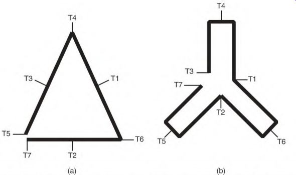
FIGURE 7.5 (a) Schematic for a constant-horsepower motor and (h) for a constant-torque
motor, connected so they won't have circulating current.
... the winding is energized. Lead T7 (or T17) is joined with T3 in the constant- torque motor and with T5 in the constant-horsepower motor.
Some three-speed motors have a two-speed winding and a one-speed winding sharing the slots. The single-speed winding will have a special internal connection that doesn't require the idle two-speed winding to be opened. If this motor isn't connected as it was originally connected, the single-speed winding will get hot (because of circulating current in the two- speed winding).
Circulating current occurs because the poles of one winding align with the poles of another winding. A proper connection will allow another pole (in its circuit) to cancel the circulating current created by an aligned pole.
A winding needs half as many circuits as it has poles, to prevent circulating current without opening it. Each internal circuit must contain two poles that are located on opposite sides of the stator. Spacing two poles of the circuit across from each other keeps them out of magnetic alignment with the poles of another winding (which has a different number of poles). This arrangement cancels current that would circulate because of the closed loop. If both windings are connected single-circuit wye, this spacing isn't necessary.
Rotor Problems in the Multispeed Motor
The multispeed motor has a squirrel cage rotor like any induction motor. It is more likely to have bars made with copper, brass, or a similar alloy. These alloys have more problems than aluminum. Rotor problems include open rotor bars, open end rings, and other problems described under "Function of the Squirrel Cage Rotor" in Section 3 (see Fig. 3.48). Open rotor bars and end rings decrease the motor's power, as described earlier. If a motor takes longer to start, or runs hotter (and more slowly) than it should, the rotor may have a problem. (Low supply voltage will also cause this problem.) Open rotor bars can be detected with a (correct size) ohmmeter attached to any two winding leads of the same winding. Turn the shaft; note the high and low readings. Departures from normal readings indicate an open rotor bar.
Rotors can be rebuilt to original specifications. They can be re-barred if made of copper or other alloy, or recast if made of aluminum. Multispeed motors are costly and hard to replace, making it cost effective to rebuild their rotors. Rotors of large motors are routinely rebuilt (Fig. 7.6).
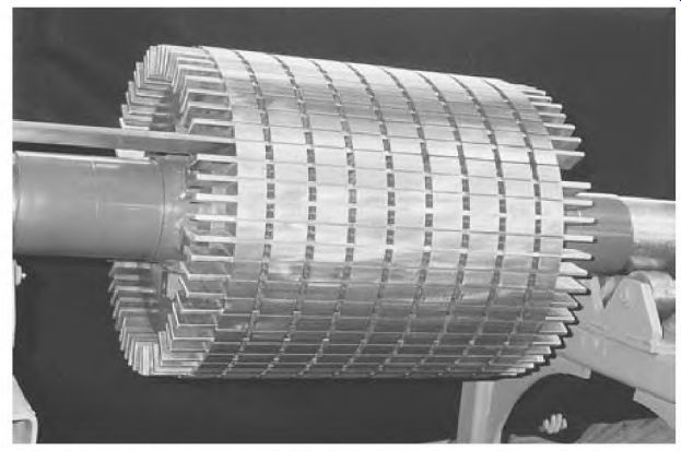
FIGURE 7.6 A rotor being completely rebuilt. Jasper Electric.
Testing Motors in Place
Test Instruments for Testing in Place
The following test instruments can be used to troubleshoot the nine- lead three-phase motor in place: clamp-on volt/ammeter, ohmmeter, megohmmeter, tachometer, induction-based test instruments, and infrared gun.
The digital clamp-on type of volt/ammeter is capable of capturing instantaneous lockout amperes. The lockout feature records the locked rotor ampere reading.
An ohmmeter and a megohmmeter are used to test slot insulation (winding lead to frame).
The tachometer is used on a loaded motor to see if it's below its nameplate RPM. Induction-based test instruments, described in Section 8, are high- frequency types of testers. They work on motors of any size.
The infrared gun locates hot spots such as poor connections. This instrument has many other uses; some are described in Section 8.
Core and Rotor Damage
If a motor has tripped its protection or blown a fuse, the cause of the disconnect should be identified before the motor is reenergized. (A failed motor that has had arcing in its slots would be unnecessarily damaged if the motor is restarted.) If a ground or short occurs in the stator slots, the motor's core and rotor will be severely damaged. Sometimes a large number of slot teeth will fuse together with melted copper. The copper must be ground, filed, or chiseled out of the core before rewinding the motor. In some cases, so many teeth are removed that the core's magnetic balance is thrown off.
If there is extensive core damage, there are three options: If repair is not economical, replace the motor. Restack the laminations, staggering the damaged laminations evenly around the stator. Replace the damaged laminations (Fig. 7.7). If an arc forms in the slot near the air gap, it's directed at the rotor.
This can melt aluminum rotor bars in just a few seconds. Motors up to 100 horsepower with this type of damage may not be (economically) repairable and therefore may require replacement.

FIGURE 7.7 New replacement laminations. Jasper Electric.
A motor connected to an ungrounded system is less likely to suffer severe core damage. It may run normally until another part of its winding, another device, or another motor on the system develops a ground.
Troubleshooting the Nine-Lead Motor (Wye or Delta) in Place
If a motor is smoking or has any other obvious major problems, it has to be replaced. The cause of the problem, however, should be identified. If the motor's history is recorded on computer, the data should be checked before troubleshooting the motor.
If someone operates the motor, get that person's input. (This may help identify the problem more quickly.) Factors of concern are load change, modifications in the machine, sound change, and history of past problems.
Load change or machine modification may' require a larger motor.
Visual Check of the Nine-Lead Motor (Wye or Delta)
If the motor has an open frame, visually check for burned windings. If you can't see the windings, check the paint on the shell of the stator. If the windings have heated excessively, the paint will look discolored or scorched where the core meets the shell. An overheated winding or bearing journal can be easily identified by the discolored paint. (Special paints are available that will change color when they reach a predetermined high temperature.) Check for a burned-winding smell in the motor's connection box if the motor is totally enclosed. Burned windings require rewinding or replacing the motor.
The preceding checks should be made before doing more extensive testing.
Check for open protection (fuse breaker or control protection). If fuses are blown or other protection is open, don't restart the motor. Restarting the motor can damage the service line components and the motor's major components (core or rotor).
Shut off and lock the motor's main disconnect switch so it can't be reenergized. Check the incoming voltage of all three lines with a voltmeter. The supply voltage should be within 10 percent of the motor's voltage rating. (If the motor can run loaded, the voltage should be tested while the motor is running.) Check for voltage unbalance. An unbalance greater than 1 percent can overheat a motor and cause failure. This problem doesn't cause immediate failure. When the motor does fail, its winding looks like those in Fig. 7.8.
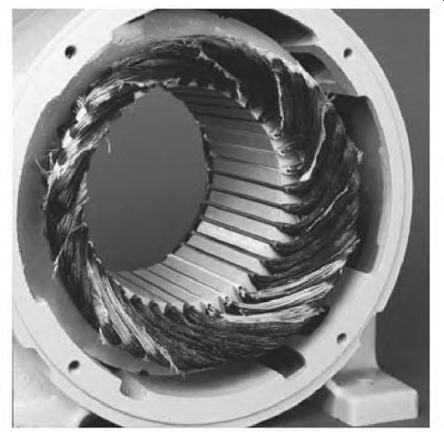
FIGURE 7.8 A winding that failed from unbalanced voltage. EASA.
Testing from Control (Wye or Delta)
If none of the visual observations shows a problem, the motor can be tested from its control (or disconnect). The following tests are done from the control.
A standard ohmmeter (multimeter) should be used to test for grounds and opens. It can also be used on the windings of smaller motors (up to 10 horsepower). A micro-ohmmeter is used to test larger motors. Induction- type test instruments will test motors of any size. These instruments are all covered in Section 8.
After the power is off and locked, use an ohmmeter to test (at the T
[motor] terminals in the control) for the following:
• Ground test from the control
• Open winding test from the control
• Open winding test (wye)
• Open winding test (delta)
• Comparison test from the control
• Rotor test from the control
Testing from the control also tests the lines to the motor. A motor that fails any of these tests must be rewound or replaced.
Ground Test from the Control
Disconnect and lock out the power. The ground tests start from the motor side (T terminals) of the control. The first test should be with a multimeter, set on ohms. (Use it first to check for a grounded winding, because it wouldn't have enough power to damage contaminated insulation.) Test from any motor terminal to the conduit. A short (or pegged) reading means that there's a ground-in the line or in the motor.
Open the motor's connection box and carefully check the motor lead connections for a possible ground to the box or to its cover. Disconnect the motor and test from the leads to the motor's nameplate-or to a clean spot on its frame. If the ground is in the motor, it has to be replaced.
Open Winding Test from the Control
Disconnect and lock out the power. Test from T terminal to T terminal with an ohmmeter. If an open circuit is found, it will be in the line or in the motor winding.
Disconnect the motor leads and check for an open winding.
If the open is found in the line, the motor has run on two lines (single- phased). There's a good chance the motor has winding damage and will look like Figs. 7.9 and 7.10 (see "Burned Windings from Operating on Single Phase" in Section 6). Normally, an open winding means the motor must be rewound or replaced.
Open Winding Test (Wye)
Disconnect and lock out the power. An open circuit in a single-circuit wye (high-voltage) connection will test open between the open phase and both normal phases (Fig. 7.9). If a nine-lead motor is connected low voltage, leads T7, T8, and T9 should be disconnected and tested separately for an open circuit.
Larger motors have more than one internal wye. In this case, the open phase has higher resistance than the other two phases. A micro-ohmmeter or surge tester will identify this problem.
If the motor runs, it has less power, and may not be able to pull its load.
The motor's sound may change (depending on its internal pole-to-pole connection) because of the magnetic unbalance within the winding.
Open Winding Test (Delta)
Disconnect and lock out the power. Figure 7.10 shows a complete circuit through two phases. The resistance is higher across T1 and T2 (the open phase) because the circuit includes two phases in series.
Both T2 to T3 and T3 to T1 show lower resistance (the resistance of only one phase). A test light will light between all leads when there's an open circuit in a delta-connected winding, and won't indicate a problem.
If the winding has multiple circuits in each phase (e.g., four and eight delta), the test results will be much the same as in the preceding test.
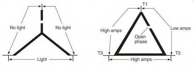
FIGURE 7.9 A single-circuit wye- connected motor with an open phase.
FIGURE 7.10 A single-circuit delta-connected motor with an open phase.
Resistance will be higher across the open phase than across the other two phases. If there's a small difference in resistance, the rotor should be turned to rule out its effect on the test. A micro-ohmmeter or surge tester will identify this problem.
Comparison Test from the Control (Wye or Delta)
Disconnect and lock out the power. Comparison-test with a (correct size ) ohmmeter or an inductance-type instrument.
From the motor's control, compare the test instrument readings from T1 to T2, T2 to T3, and T3 to T1. (They should be identical.) If there is just a small difference, turn the motor's shaft slowly at least two complete turns while doing each test.
The rotor bar's position can make a difference in the readings. Note the high and low on all three tests.
A difference in readings between lines indicates a shorted winding or a high-resistance connection between the control and the motor. The motor should be disconnected and tested separately before it's removed.
There's no exact resistance value specified in a motor winding (related to its horsepower and speed) because there are many variations of windings and core length designs.
Two identical test instruments may not give exactly the same readings.
This fact should be considered when using a specific test value.
Comparison-testing between winding circuits is the most dependable way to locate winding problems. This can be done quickly on motors of all sizes, and doesn't require manufacturer's specifications.
Rotor Test from the Control
This test should be done if the motor doesn't have normal power (if it takes longer than previously to start the load, or if the shaft speed [loaded] is lower than the nameplate RPM). Disconnect and lock out the power. The rotor test can be done during the comparison test. When turning the shaft during the ohmmeter or induction test, look for a departure from the high and low readings. If a larger departure happens at the same shaft position, the rotor has an open rotor bar (or bars). If a departure is noted at several equally spaced shaft positions, it could be the rotor's design.
Starting the Motor After the Comparison Test from Control
If the motor isn't open or grounded and the comparison test is even, the motor can be started. Check the amperes of all three lines, and compare the results with the motor's nameplate. (There's always a small difference in ampere readings between lines.) To verify that the motor has no problem, use the procedure described in the following section.
If the amperes are normal, it's important to find out what caused the disconnect to open. If the cause of the problem isn't found, the incident should be recorded for future reference. Possible causes are covered under "When Motors Overheat" in Section 6.
Line/Lead Interchange Test for Uneven Amperes
Most three-phase motors will have different ampere readings on all three lines, especially when the motor has no load. If the amperes are quite uneven, the problem lies in the power supply or in the motor winding.
This can be determined by first recording the amperes of each line and then interchanging all three lines or all three motor leads, whichever is easier. (Changing all three keeps the rotation the same.) If all three lines keep the same readings, the problem lies in the line. If all three motor leads keep the same reading, the problem lies in the motor.
Recording Motor Faults
A history of motor breakdowns is valuable in maintaining production. Future problems are then easily recognized and possibly prevented. Ideally, a plant's motor problems are all recorded on a good software program.
A well-designed report sheet makes recording problems easier. It should include a sketch of a stator showing the location (top, bottom, front, back) of the breakdown. For example, a breakdown that occurs frequently at the bottom of the motor indicates a moisture problem. (Simply drilling a drain hole may be the solution for this particular problem.) Most failures are visible, but the fault should be recorded, with reference to a lead number.
Schematics of the wye and delta nine-lead connections should be used to reference the location of all breakdowns (according to lead location). Line conditions should be recorded. These include voltage and amperes of each line (no load and full load). If possible, the readings should be taken both at the control and at the motor.
Locating Motor Faults Test Equipment for Locating Motor Faults
Locating and identifying motor faults can pinpoint failure causes. This is an important part of preventive maintenance. A motor service center should identify, whenever possible, the cause of failure. Identifying a failure is especially important with motors that are replaced rather than repaired.
Limited single-phase current works very well for testing three-phase stators. Figure 7.11 is a diagram of a test panel that can be constructed with stove elements. The test panel can be designed for higher current. Low- resistance grids can be used if more amperes are needed.
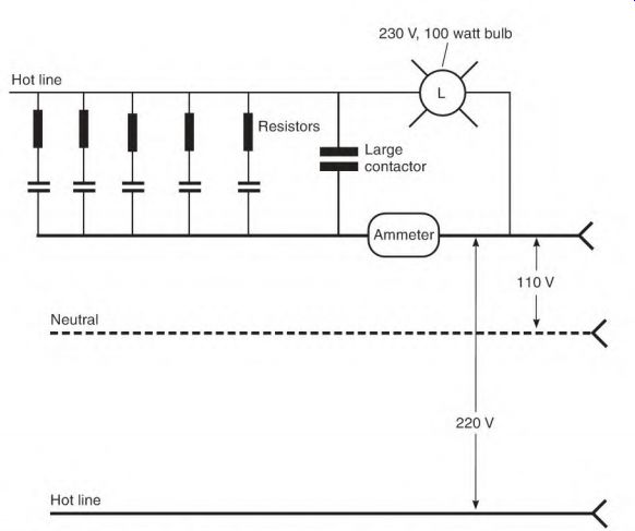
FIGURE 7.11 Circuitry of a test panel, using resistors.
This test panel can also be used with a higher hertz power supply than 60 Hz. (Locate the ammeter on the 60-Hz side of the power supply.) Higher hertz creates more inductance and lowers the amperes and torque of a motor being tested.
High-hertz test instruments create more inductive reactance than do 60-Hz test instruments. A few shorted turns are much more apparent with induction-based test instruments than with an ohmmeter.
An ohmmeter uses low-voltage DC and measures only the resistance of the wire. The short length of wire contained in shorted turns (that are eliminated from the phase) has very little resistance. Identifying a faulty phase by comparing its resistance to two normal phases is harder to do with an ohmmeter.
This type of motor testing should be done in a dry location, because if the winding is grounded to the frame, the test can be dangerous. The motor may" have to be disassembled to accurately diagnose and locate the winding fault.
The test results that follow are described as high or low resistance (when using an ohmmeter), or low or high amperes (using limited single-phase current). The term high resistance on an ohmmeter is the same as low current with limited single-phase current.
Locating Shorted Turns in a Wye-Connected Nine-Lead Motor
In this case scenario, the motor winding being tested is a nine-lead wye connection with shorted turns in phase A. The breakdown isn't visible. It was operating on high voltage when it failed.
First, check the rotor winding by turning the shaft, using an ohmmeter or limited current. Compare the high/low readings as described earlier.
(The stator winding can be checked more quickly and easily with the rotor removed, but it isn't required.) The motor's shorted A-phase winding has less resistance than the B and C phases (Fig. 7.12). Because of the wye connection, there is lower resistance (or higher amperes) from the faulty phase lead (T1) to both of the other phase leads (T2 and T3). When the two normal phases (T2 to T3) are checked, they will have higher resistance (or lower amperes) because the shorted turns aren't included.
If more than one phase has shorted turns, all three phases will have different readings.
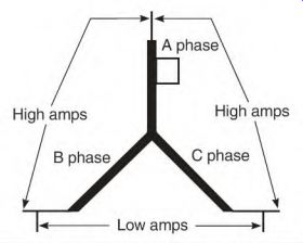
FIGURE 7.12 A single-circuit wye-connected motor with an open phase.
If the short isn't visible, the exact location of the shorted turns can be determined by disconnecting leads T4 and T7. Compare the circuits T1 to T4, T2 to T5, and T3 to T6. If the test results of circuits T2 to T5 and T3 to T6 are identical, but different from that for T1 to T4, the problem lies between T1 and T4.
Now cut the tie cord and carefully lift the T1 lead. If the short is found close to T1 (within the first two to three turns), the breakdown may have been caused by a voltage spike.
If the T1 to T4, T2 to T5, and T3 to T6 test results are identical, compare T7 to T8, T8 to T9, and T9 to T7. Record the lead number that shows a difference to both of the other leads in the circuit. A problem in this circuit wouldn't be spike-related unless the motor had been operating on its low- voltage connection.
Locating Voltage Spike Damage in a Wye-Connected Nine-Lead Motor
Voltage spike damage has increased with the use of variable-hertz drives.
This problem can be reduced with properly placed reactors, surge capacitors, or tuned filters. Power quality test instruments can be used to determine the likelihood of spike-causing conditions. Figure 7.13a shows an instrument used for this test.
FIGURE 7.13 (a) Testing the power quality with a handheld oscilloscope. Fluke.
(b) Winding damaged by a spike. EASA.
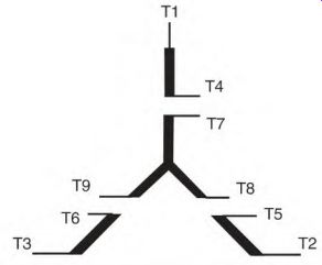
FIGURE 7.14 Check points for finding spike damage in a nine-lead wye-connected
motor (connected low voltage).
Spike damage occurrences increase when the distance between the control and the motor is more than 50 feet. This will cause a breakdown within the first two to three turns of a line lead. This breakdown characteristic is unique to spikes and is easy to identify (Fig. 7.13b). If the motor was operating on low voltage, test each circuit separately, as shown in Fig. 7.14. The leads that connect to lines are T1 and T7 for line 1,
T2 and T8 for line 2, and T3 and T9 for line 3. If the damage is not visible, each identical circuit should be comparison-tested (T1 to T4, T2 to T5, T3 to T6, T7 to T8, T8 to T9, and T9 to T7). A brief description of the breakdown and its location should be entered in the motor's software for future reference.
In this case scenario, the motor winding being tested is a nine-lead delta connection, with shorted turns in phase A. The breakdown isn't visible. It was operating on high voltage when it failed (Fig. 7.15). First, check the rotor winding by turning the shaft and comparing the high and low readings. (The stator winding can also be comparison-tested with the rotor removed.)
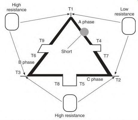
FIGURE 7.15 Checkpoints for locating a shorted phase in a nine-lead delta
connection (connected high voltage).
The motor's A-phase winding has shorted turns. This means it has less resistance than the B and C phases (Fig. 7.16). Because of the delta connection, there will be lower resistance (or higher amperes) across the faulty phase leads T1 to T2. When the two normal phases (T2 to T3 and T3 to T1) are checked, they will have higher resistance (or lower amperes) because the shorted turns aren't included. Some current will flow through the faulty phase when the normal phases are tested. This current will affect both normal phases the same, and the readings will be identical. All three phases will have different readings if more than one phase has shorted turns.
The exact location of the shorted turns can be determined by disconnecting all leads and comparing the identical circuits. Identical circuits are from T1 to T4 and from T1 to T9. They should have the same readings if there are no problems. The same is true from T2 to T5, T2 to T7, T3 to T6, and T3 to T8.
The comparison test shows less resistance (or higher amperes) between T1 and T4, which locates the shorted turns. Check the shorted turns between T1 and T4 for a possible spike-caused breakdown.
If the delta-connected motor is operating on low voltage, a spike-caused breakdown will occur close to any lead connected to a line. The low-voltage connection subjects all leads to spike damage (Fig. 7.17). The location of the shorted coils may point to the cause of the breakdown. (A current-conducting contaminant that settles on a winding will affect the coils that it covers.)
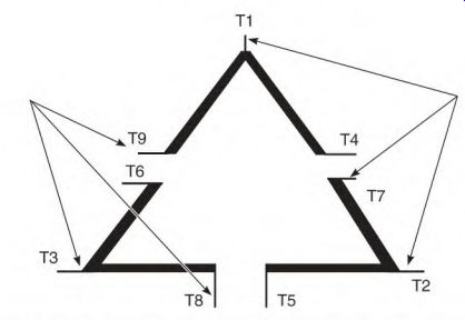
FIGURE 7.17 All leads are subject to spike damage when connected low voltage.
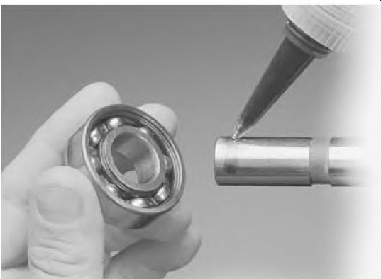
Fig. 7.18
A brief description of the breakdown and its location should be entered into the motor's software for future reference.
Megohmmeter Test for Ground
A megohmmeter (see Section 8) is a popular instrument for testing slot insulation. The test is done from a winding lead to the frame. A megohmmeter will show infinity when the winding is good.
If the megohmmeter shows from 2 to 50 megohms to the motor's frame, the motor can still be used, but it should be cleaned and baked dry at the earliest convenience. Follow with a varnish treatment. (The chemical components of new varnish must be compatible with the original varnish.) Moisture-caused breakdown usually occurs at the bottom side of the lowest coil in the stator. (A water line is often visible on the bottom coils.) This type of breakdown is normally from the winding to the frame (ground) in the lowest slot.
Conducting contaminants cause breakdown in the areas where they accumulate. Breakdowns will occur on top of the top coils, and on the top of the bottom coils.
Be sure to ground the motor leads to the frame after the test.
Bearing Maintenance
Bearing failure causes a high percentage of electric motor breakdowns.
Good bearing maintenance is essential for maximum bearing life. The maintenance schedule, the right lubricant, and the amount of lubricant should fit the needs of the motor and its running conditions. (If there is frequent bearing failure, adjusting one or more of these three factors may be all that's necessary.) Bearings should be replaced if a motor is disassembled for any reason (if it has been in service for a year or more). The cost of new bearings is minimal when compared to the cost of downtime or the cost of replacing or rewinding the motor.
Bearings are manufactured in a sterile, dust- and lint-free, air- conditioned, low-humidity environment. Cleanliness is very important when handling ball bearings. (A grain of sand or a few iron fillings can destroy a bearing prematurely.) It should be wrapped in a grease-compatible plastic as soon as it is removed from the motor's end bracket.
All motor components, tools, and work surfaces should be clean before a new bearing is unwrapped. Immediate motor assembly and bearing installation is recommended. If this is not possible, the bearing should be re wrapped.
A new bearing should never be washed. If the bearing is submerged in oil for heating/installation, the oil must be clean or (preferably) new.
Motor Storage Concerns
Motors should be stored in a dry, clean, vibration-free environment. Humid weather can cause condensation inside a motor. Condensation can be minimized by maintaining the storage room temperature 15 to 20 degrees above the outside temperature.
DC motors develop commutator corrosion in a high-humidity environment. In addition, brush boxes rust, resulting in stuck brushes.
Remove the brushes from their boxes and relax the spring tension (for long- term storage). Turn the motor's shaft a few revolutions at least once a month-daily if there is a vibrating problem. This redistributes the grease and recoats the contact surface between the ball and race.
Ball bearings eventually force their way through grease and make metal-to-metal contact with the races. (If there is vibration, the metal-to- metal contact accelerates, and destructive wear is certain.) The balls wear the races, creating wear spots equal to the ball spacing. This is called false brinelling. Bearings with this problem are noisy and will fail prematurely, even if the motor is new.
Motors in service can also have false brinelling if they sit idle for long periods in a vibrating environment. Turning the shaft or running the motor every day will minimize this problem.
Bearing Failure Causes
Mechanical causes of bearing failure include vibration, excessive belt tension, misalignment, housing or shaft distortion, wrong internal clearance, and preloading from axial thermal growth of the shaft.
Vibration
Many early bearing failures are caused by out-of-balance motor and/or load components. Motors should be balanced to accepted specifications.
A vibration check should be made on the mounting base of a motor.
The base shouldn't vibrate more than one-third of the acceptable balance specified for the motor itself. Keeping a history of all vibration tests is recommended.
Excessive Belt Tension
Belts should be tightened only enough to keep them from slipping. Formulas for this recommend about 1/64 inch of up-and-down belt movement per inch between shaft centers. Worn grooves in the drive pulley" require excessive belt tension.
Misalignment
Misalignment is a frequent cause of vibration and preloading-related bearing failure. Although couplings are built to flex and accommodate some misalignment, it should be kept to a minimum. Laser alignment is a very precise method of alignment.
Housing or Shaft Distortion
When the shaft or housing is distorted, the affected bearing race will distort accordingly. The bearing will run hot and will fail prematurely. Check both the shaft and the housing if there is frequent bearing failure.
Wrong Internal Clearance
Bearings have internal clearance that allows for two factors: shaft expansion (from heat) and interference fit (or press fit, which keeps the bearing race from slipping). The extent of shaft (and housing) expansion is related to the motor's enclosure, size, and cooling method. The amount of interference fit varies from motor to motor.
Heat develops in the squirrel cage rotor and travels to the shaft, causing it to expand. The end bracket (end bell) dissipates this heat through the bearing's outer race. (The motor's cooling fan gives the end bracket a different expansion rate than that of the shaft.) The expansion of the shaft and the pressed fit of the end bracket must be absorbed by the bearing's internal clearance. Motor manufacturers select bearings that fit these requirements. Replacement bearings must have the same specifications as the original ones.
Bearings are manufactured with clearance ratings that allow for expansion (for example, C4). If there isn't enough clearance, the bearing will run hot, causing the grease to fail.
Smaller motors (fractional to 10 horsepower) often have excessive clearance in either the shaft fit or the housing fit. The bearing, which is much harder than either the shaft or the housing, will slip or spin while the motor runs and will wear away material from these components. Over time, a very loose fit develops. This allows the rotor to drag on the stator.
To prevent this problem, an epoxy developed for this purpose can be used (Fig. 7.18). The epoxy remains resilient and allows for expansion, but keeps the bearing race from moving.
FIGURE 7.18 An epoxy designed to keep a bearing race from rotating. Locktite
Corp.
Axial Shaft Expansion
Axial expansion occurs as a motor comes up to its running temperature. If the expansion isn't allowed for, preloading becomes a problem. Preloading causes the bearing to overheat and fail prematurely.
The amount of axial expansion is related to the length of the shaft.
Thrust washers (made of spring steel) are used to absorb the axial expansion in some motors.
Other motors have hubs that hold the shaft-end bearing captive. The opposite bearing must have room for the shaft's axial expansion. (This can be checked after the motor is completely assembled.) Loosen the hub opposite the shaft. If the hub cover moves outward when the bolts are loosened, the bearing is preloaded. Shims can be used to re-space the hub cover. If spring steel thrust washers are used, they shouldn't be completely compressed.
Some motors have a smaller bearing on the end opposite the shaft.
Manufacturers do this to cut costs.
Lubrication Schedule and Bearing Life
The lubrication schedule and the type of lubricant are determined by the type of load and the ambient conditions. A belted load needs lubrication more often than a direct-coupled load. Motors that operate under extreme conditions (hot, cold, wet, frequent starts, vibration, etc.) need to be greased more often.
Counter to many grease manufacturers' claims, there is no one grease that fits all conditions. Nor is there a specific lubrication schedule. However, a motor can't be lubricated too often (provided the lubrication is done correctly). Grease scheduling should be frequent enough that the old grease doesn't become caked or hardened. (Forcing hardened grease through the bearing while the motor is running can damage a bearing.) Motor manufacturers estimate bearing life at up to 100,000 hours if the motor is direct-coupled and around 50,000 hours if it has a belted load.
This estimate assumes that a good grease schedule is followed (with the right grease) and that the motor operates in ideal conditions. The speed of the motor, balance (of both motor and load components), and ambient conditions must be considered for individual bearing life expectancy. (Ideal operating conditions are rare.)
Grease Types
Grease is made of various materials that will hold oil. Oil is released from the grease over a period of time. When all the oil has been released, the consistency of the remaining material can range from firm to hard.
Grease types are designed for various conditions. It's important to select a grease type that fits the condition. A selection of grease types follows:
• Petroleum oil grease is the most common (with a temperature range of 30° to 300°F).
• Diester oil grease is used for cold conditions as low as -100 0 F.
• Silicon grease is not recommended for heavy loading but has a wide temperature range (-100° to 300 0 F). Silicon grease of any type shouldn't be used in a DC motor. Fumes from silicon break down the brush material next to the commutator, resulting in excessive brush dusting.
• Fluorosilicone grease works well where it might become diluted with solvents or chemical contaminants. (It also shouldn't be used in a DC motor.)
• Per-fluorinated polyether greases stand up under temperatures as high as 550 0 F and have good load-carrying capability.
Mixing different types of grease can cause bearing failure. If they're not compatible, the greases will Liquefy or will combine and become thick. In either case, the bearing lubrication won't be effective. Figure 7.19 shows compatible and non-compatible greases.
Change Grease Types
The right way to change incompatible grease types is to remove the bearing and wash it thoroughly with solvent, before filling it with new grease.
However, in most cases, this procedure takes too much time.
The method that follows, under "Lubrication Procedure," is recommended, with the following modifications. Flush the old grease for a longer time than described (to remove as much old grease as possible). Grease the motor using this procedure at least three times (at no more than one-week intervals).
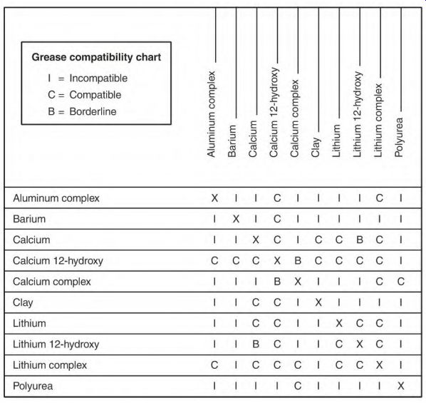
FIGURE 7.19 Compatibility grease chart.
Lubrication Procedure
High-pressure greasing equipment should not be used on motors. Nor should grease be forced into the bearing at a fast rate with a hand-operated grease gun. That would force grease through the bearing seal and onto the winding of the motor.
Grease won't break down the motor's insulation. However, it does impede the dissipation of heat from the winding. If grease gets into the air gap between the rotor and stator, the motor becomes excessively loaded.
If the motor has grease fittings, called zirks, a purge plug should be at the bottom of the bearing enclosure. Remove the purge plug and clean the grease zirk thoroughly. Run the motor, and pump the grease through the bearing slowly, until about half an ounce of new grease comes out of the purge hole.
The motor should run at least 2 hours before the purge plug is replaced.
(This allows the bearing to expel excess grease.)
A bearing should be filled when hand-packing it with grease. But the motor's bearing housing should be filled to only about one-third. This gives the bearing room to expel excess grease. If it can't expel excess grease, the grease will churn, causing it to release its oil too soon. (All grease types are designed to release oil over a long period of time.) Shielded (or sealed) bearings should be used if there is no purge plug.
Replace the grease zirk with a plug, and tag the motor to prevent installation of another grease zirk.
Alternate Lubrication Methods
If the motor is in a remote location or needs lubricant at frequent intervals, self-actuated grease cups can be installed. They're available in battery- operated and gas-operated types and are designed to apply lubricant daily, weekly, bimonthly, or monthly. Extreme temperatures may affect the timing of the gas-operated types.
Oil mist is a method of lubrication that works well on high-speed machines. The oil is atomized, and is delivered with a mixture of air to the bearing under pressure. With the bearing enclosure pressurized, moisture and other contaminants are kept out. Normally the oil mist is applied for a short time before starting (to make sure the bearings aren't dry). Oil injection is another effective way of lubricating bearings. A measured amount of oil under pressure is squirted directly into the bearing.
Gearbox Lubrication
Gearboxes have an oil level that should be checked at regular intervals.
Oil change should be done once a year under normal conditions. If the operating temperature goes above 200 F, oil change every 3 months is recommended. An infrared gun can determine the running temperature of the gearbox.
High humidity and wide temperature swings cause condensation inside the gearbox. The oil will become a whitish color when extreme condensation is a problem.
Particle Analysis
A regular program of particle analysis is recommended for gearboxes, which are vital to the operation of an industry. Wear particles from each component can be identified as well as any outside contaminants. Once a record of wear has been established, any abnormal increase is easily detected. Repair can then be done before a catastrophic failure occurs.
Particle analysis is also done with grease. This service can be used to solve frequent bearing failure problems.
Particle analysis is described in detail in Section 8.
Shielded Bearings
Single-row bearings with shield(s) or seal(s) are used in most standard-duty electric motors. (Shields are used more often than seals.) A shield retains grease well, but does not keep out all contaminants. Inactive grease (next to the shield) keeps out some (but not all) types of contaminants.
Some motors have bearings with only one shield (facing the rotor) for retaining the grease. If grease is forced into this bearing too fast, it will go through the shield and onto the motor's winding.
Sealed Bearings
Sealed bearings have flexible seals that rub the inner race. The seal has a small amount of drag that decreases the motor's efficiency slightly. If a motor has to operate where sealed bearings are needed, efficiency can't be a factor.
Seals keep out fine dust and contaminants of that nature. They are available in single, double, and triple seals.
If it isn't possible to keep a timely lubrication schedule, the use of shielded or sealed bearings is recommended.
Labyrinth Seal
The labyrinth seal is a noncontact seal that keeps contaminants out of bearings very effectively (Fig. 7.20). High-speed applications need a noncontact type of seal.
Contaminants do several direction changes after entering the seal. When they get to a cavity between the rotor and stator, they are expelled through a purge hole. Any contaminant that isn't expelled is held by centrifugal force until the shaft stops. At this point, an O-ring, held by centrifugal force, pulls together and seals off the path where the contaminant could have entered the bearing. (The movable O-ring also seals in any bearing lubricant that would flow out.) At rest, the motor is hermetically sealed.
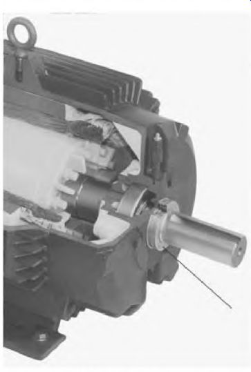
FIGURE 7.20 A noncontact seal that keeps most contaminants out while keeping
the grease in. Inpro/Seal Co.
Labyrinth Seal Construction
The labyrinth seal has two major parts: a rotor (Fig. 7.21a) and a stator (Fig. 7.21b). Both parts have O-rings that isolate the motor bearing from outside contaminants.
The motor housing must be machined to accept the stator. The stator has an O-ring and a press fit. The O-ring and the tight pressed fit combine to seal the stator.
The rotor has two O-rings as well as a pressed fit. One O-ring seals the shaft from outside contaminants and is stationary. The other O-ring is movable and contacts both the stator and the rotor when the motor is at rest, hermetically sealing it. When the motor runs, this O-ring is pulled away from the stator by centrifugal force. It is held away from the stator by centrifugal force in a space machined into the rotor. There is no contact between the stator and the rotor shaft while the motor runs. Consequently, there's no wear or efficiency" loss.
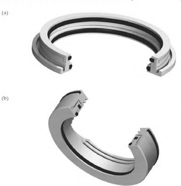
FIGURE 7.21 (a) The labyrinth seal (rotor). Inpro/Seal Co. (b) The labyrinth
seal (stator). Inpro/Seal Co.
Many motor manufacturers use the bearing isolator (labyrinth) seals in their premium motors. This seal allows them to extend the bearing life warranty. The motor's efficiency is not affected.
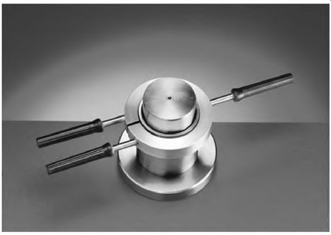
FIGURE 7.22 The aluminum heating ring for removing the inner race of a ball
bearing. SKF USA Inc.
Bearing Removal
Disassembling a motor (for bearing removal) must be done carefully. First, remove any bolts or screws that hold the bearing captive. Then remove the bolts (or through-bolts) that secure the end brackets. Loosen the end bracket with a soft hammer (plastic shot-filled or a lead hammer) and a dull chisel.
Some end brackets have ears on both sides for this purpose. If there's a deep flange fit, tap both sides of the end bracket uniformly. Avoid using a steel hammer.
Bearings should be removed by pulling from the inner race. Very few motors, however, leave access to the bearing's inner race, so a bearing puller has to be used on its outer race. (This is why bearings should be replaced if they are removed.) A steel washer between the point of the puller and the shaft will keep the shaft's centering hole from being damaged.
If a bearing has spun on the shaft-and seized-when it failed, it may be necessary to use a torch to remove the inner race. This should be done without damaging the shaft. The shaft should be checked with a micrometer and, if necessary, repaired (to its original dimensions). If there is no shaft damage, the inner race can be removed with an aluminum heating ring (Fig. 7.22). Remove the outer race and bearings, and wipe the inner ring clean. The heating ring is heated to around 500 F, then clamped around the inner race. The race will loosen enough for removal.
Bearing Installation
One of the most important requirements for bearing installation is cleanliness. This includes tools, the motor components, and anything that has contact with the hearing.
Small bearings can be installed with a tube that fits the bearing's inner race, and a soft hammer.
A hydraulic bearing press can be used for larger bearings. Pressure has to be uniformly applied to the bearing's inner race only.
Heating is a popular method of bearing installation. Never use an open flame. The bearing should be heated uniformly and slowly. If the inner race is heated too fast, its rapid expansion will damage the bearing's components, resulting in a noisy bearing.
Overheating is a major concern when any heat method is used to install bearings. The bearing should not be heated over 230° F. A properly heated bearing should be pushed in place on the shaft without stopping. The inner race will shrink and stick to this spot. If it isn't in place, it will have to be pressed the rest of the way. When a bearing is installed using heat, it will shrink axially a minute amount. Rarely would this be a concern in an electric motor.
Hot oil is a good way to heat a bearing, if done properly. It uniformly heats the bearing, and protects it from rust for a short time.
The oil must be clean and should have a flash point above 480 F, to reduce fire hazard. Also, care must be taken not to overheat the oil because of possible acid buildup.
The hot oil method works best with open bearings that are greased after installation. If the bearing is shielded, oil may dilute the grease.
A heating cabinet is a good method of heating a bearing. The bearing can be kept at the proper temperature in a clean environment for as long as needed using this method.
Figure 7.23 shows an automatic induction bearing heater. This unit goes through a number of important steps. A magnetized temperature sensor is placed on the bearing's inner race. Power is automatically applied intermittently, allowing the heat to migrate to the outer race, which uniformly heats the entire bearing. Once the right temperature is reached, the bearing is demagnetized. Some types of induction heaters don't magnetize the bearing.
The problem with most heating methods is the time and attention involved.
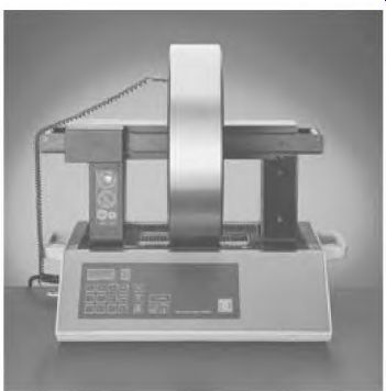
FIGURE 7.23 An automatic induction bearing heater. SKF USA Inc.
Identifying Bearing Breakdown Causes
If a motor has frequent bearing failure and the cause isn't obvious, an effort should be made to discover the cause.
The best time to identify the cause of failure is when the bearing begins to get noisy. Mark the bearing's outer race, the housing, the inner race, and the shaft (for reference) while disassembling the motor. This provides a reference point-that is, direction of belt load pull. The bearing can now be broken open to determine the cause of its failure. Some bearing companies provide pictures of failed bearings and identify reasons for their failure.
Bearing Current
Signs of current-caused bearing failure include uniform fluting pits across the inner and/or outer race and inline pits evenly spaced on the balls (Fig. 7.24). When a voltage potential exists between the shaft and the stator, the current path is through the bearings. The voltage is usually low, and the lubrication between the bearing components has resistance that stops current flow.
There are times, however, when there is metal-to-metal contact. Current flows at this time between the races and the balls, forming a circuit between the shaft and stator.
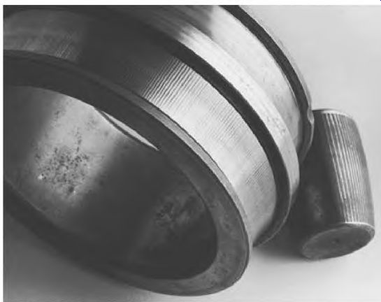
FIGURE 7.24 The marking found in an electric current-caused bearing failure.
SKF USA Inc.
There is no damage to the bearing when current flows through it.
(Damage occurs when the circuit is broken.) An arc forms between components at this time. (The same kind of arcing occurs when switch contacts open, and break a current-carrying circuit.) Some of the metal vaporizes, leaving pits. Eventually axial lines (fluting) form across the races.
Pits form in the balls, the bearing becomes noisy, and it soon fails.
Bearing current breakdown was a rare problem in the past. Variable- frequency drives are linked to an increase in this problem.
Attempts at solving this problem include using current-conducting grease; insulating the bearing from the housing; grounding brushes from shaft to stator; coating the outer race of the bearing with a hard, high- resistance material; and using ceramic balls.
Conductive grease is one of the least successful. The grease has to maintain a conductive path large enough for all the current to flow between the shaft and the end bracket. The active grease is very thin-between the balls and races. Supplying enough grease to ensure good conduction would cause the grease to churn and overheat.
Insulating between the bearing and housing can lower the mechanical strength of a motor.
A grounding brush has been used, with varying results. It must be made of a very low-resistance material (with a high metal content for conducting the low-voltage-driven current). The wear factor between a high-metal- content brush and shaft will be high. A small amount of resistance between the brush and shaft sends current through the bearing, which is a parallel circuit.
A bearing with its outer race coated with hard insulation works well.
Such bearings are interchangeable with standard-size bearings and require no alteration of the motor housing. Bearings with ceramic balls also work well.
In extreme cases of bearing current, a combination of a grounding brush and coated bearings can be used. The grounding brush will conduct higher- voltage-driven current that can bypass the bearing's coating. The bearing's coating will stop lower-voltage-driven current that the brush can't conduct.
The best solution is to eliminate the destructive voltage.
Bearing current problems occur in DC motors when their stator field is grounded, or when the power supply is grounded. Bearing current is also a problem with DC motors that are mounted on an electrically common machine, such as a locomotive.
Specialized Bearing Tools
There are many specialized tools for bearing handling. Proper use of them will prevent damage to the bearings, shaft, and outer housing. There are many cases of early bearing failure linked to faulty installation procedures.
Training courses offered by bearing companies are highly recommended.
The courses teach correct procedures with specialized tools and timesaving methods.
Bearing pullers are available in many variations. Mechanical pullers for small to medium-sized bearings have two or three jaws for gripping the outer ring of the bearing (Fig. 7.25).
FIGURE 7.25 One of many types of bearing pullers. Industrial Pulley Puller.
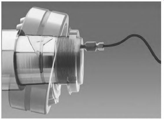
FIGURE 7.26 The oil injection method of bearing removal. SKF USA Inc.
Hydraulic-powered tools are used for larger bearing removal and installation. A hydraulic press is also used for removal and installation.
Oil injection is used for bearing removal. The shaft is modified as shown in Fig. 7.26. Oil is forced between the bearing's inner race and the shaft as the bearing is pulled off.
Hydraulic nuts are a tool used to mount bearings. Roller bearings can be mounted precisely on a tapered shaft, using this tool. This type of bearing must be mounted precisely for maximum life.
Sleeve Bearings
Most fractional-horsepower single-phase motors have sleeve bearings. The bearings are lubricated with oil-impregnated wicking, which lasts for the life of the motor. Most of these motors have no allowance for lubrication, but can be taken apart to apply oil directly into the oil reservoir. Holes for oiling can be drilled into the bearing cap or the end frame. These motors are usually replaced instead of repaired.
Larger motors with sleeve bearings have an oil ring and an oil reservoir.
(The volume of oil needed for large bearings can't be supplied with a wick.) The oil ring rides directly on the shaft, with about one-third of the ring submerged in oil. As the shaft turns, the ring turns with it, carrying oil to the bearing. Oil lubricates all parts of the bearing by flowing through slots along the length of it, and back to the reservoir.
Sleeve bearings in large high-speed motors should be well oiled before they are test-run with no load. This prevents them from being destroyed (wiped) before the oil ring supplies oil.
It's normal to have about 1/2 inch of endplay in larger sleeve bearing motors. When the motor runs, the rotor will seek its magnetic center. (The shaft shoulder shouldn't ride against the bearing.) The oil level should be checked once a month, and the oil changed once a year. If contaminants or high temperatures exist, the lubrication schedule should be altered accordingly.
Unlike single-phase motors, three-phase motors with worn sleeve bearing don't show signs of the problem (by becoming noisy). To check for wear, move the shaft back and forth in the direction of the load. There should be no lateral shaft movement.
Section 7 Review
1. A failing connection in the DC field/resistor of a synchronous motor's control circuitry" will cause the DC field to break down (24). T F
2. A shorted DC field coil can prevent the rotor from reaching pullout speed (24). T F
3. The amortisseur (squirrel cage) winding (if accessible) can be checked with an infrared gun (25). T F
4. A warm end ring and cool rotor bar is the sign of a broken rotor bar (26). T F
5. The ohmmeter should always be the first instrument used to test from winding to frame (26). T F
6. The vacuum/pressure impregnation (vpi) varnish method is the preferred method of coating and filling all voids in a form-wound winding (326-327). T F
7. An uneven air gap can accelerate bearing wear (27). T F
8. The line-to-line comparison test is done first when testing a two-speed motor (327-328). T F
9. The surge test should always be applied to both speeds when testing a two-speed motor (329-330). T F
10. A multiwinding motor is tested as though it is two different motors (329-330). T F
11. When testing a multiwinding motor, the winding that is not being tested has no effect on the test being done to the other winding (329-330). T F
12. The lead T7 (or T17) is not needed in some two-winding, three-speed, three-phase motors (330-331). T F
13. The lead T17 is used on the (330-331)
a. low-speed winding.
b. high-speed winding 14. Defective rotors can be completely rebuilt (32). T F
15. In some cases, a failed motor can be severely damaged if it is reenergized (33). T F
16. Extensive core damage can be repaired or replaced (33). T F
17. Operator input is an important part of troubleshooting (34). T F
18. Visually checking for obvious signs of catastrophic problems should be done before using test instruments, and often saves time (334-335). T F
19. Checking the voltage and amperes while the motor is operating-fully loaded-should always be done after a motor is installed (35). T F
20. Many serious motor faults can be detected at the control or disconnect (36). T F
21. Testing all circuits from winding to frame should be done (first) with an ohmmeter. If the motor fails this test, it may need to be replaced or rewound (36). T F
22. Open-winding symptoms are the same whether the motor is connected wye or delta (336-337). T F
23. A comparison test-at the motor control-should be done before energizing a newly replaced motor (38). T F
24. What are two signs of rotor problems (38)?
25. When is the line/lead interchange test done (39)?
26. A preventive maintenance program must include the reason a motor failed (339-340). T F
27. The chance of spike damage from variable-hertz drives will increase when the motor is over 50 feet from the drive (342-343). T F
28. If there is a short in one phase of a delta-connected motor, that phase will have less resistance than the other two (344-345). T F
29. The megohmmeter can be used to comparison-test a three-phase winding (46). T F
30. Bearing failure causes a high percentage of motor failures (346-347). T F
31. It's important to clean a new bearing before installing it (47). T F
32. A new motor that has been stored where there is vibration can have noisy bearings (false brinelling) (47). T F
33. If a stored or seldom used motor must be in a vibrating environment, false brinelling can be prevented by spinning the shaft on a regular basis (347-348). T F
34. Belt tension should allow movement of inch per foot between shaft centers (48). T F
35. A ball bearing's internal clearance should allow for interference fit and heat expansion (348-349). T F
36. If a ball bearing's interference fit is too loose-on the shaft or the housing-the component must be altered to eliminate slipping (49). T F
37. The amount of axial expansion is related to the outside diameter of the bearing (50). T F
38. Grease is available for many types of adverse environments (350-351). T F
39. A good lubrication schedule is once a year (50). T F
40. Mixing different types of grease always causes bearing failure (51). T F
41. Bearings must be replaced when changing to an incompatible grease (51). T F
42. High pressure should be used to make sure enough grease gets to the bearing (52). T F
43. Name three alternate lubrication methods (53).
44. Gearbox oil should be changed according to the operating conditions (53). T F
45. Preventive maintenance for gearboxes should include particle analysis (353-354). T F
46. What is the difference between shielded and sealed bearings (54)?
47. The labyrinth seal uses centrifugal force to expel contaminants (55). T F
48. If a ball bearing is removed from a shaft, it should always be replaced (356-357). T F
49. A bearing should not be heated over 230 F (58). T F
50. The time to identify the cause of frequent bearing failure is when it starts to become noisy (59). T F
51. Bearing current failure is caused by current flow interruption within the bearing (359-360). T F
52. Worn sleeve bearings aren't always noisy in three-phase motors (63). T F