AMAZON multi-meters discounts AMAZON oscilloscope discounts
The Dual-Voltage Nine-Lead Motor's Internal Connections
Costly mistakes can be avoided if the technician understands the two types of connections used in the nine-lead motor. Testing can be done accurately and with confidence if the connections are fully understood.
The dual-voltage nine-lead three-phase motor is internally connected wye or delta. Data found between lead numbers are very different in the two connections. Some winding failures in a wye-connected motor will have a different look from those in a delta-connected motor-even when both have the same basic problem. Test results will also be different.
It's important to identify the cause of burned windings. They will have a different appearance in all these situations: single-phase burnout, overload, unbalanced voltage, and voltage spikes. (Voltage spike damage occurs more often in motors controlled by variable-hertz drives.) These problems are all caused by in-plant faults that require correction. A replacement motor can fail-sometimes immediately-if the in-plant problem isn't corrected.
Nine leads make it possible to operate a three-phase motor on either of two voltages. The two connections have a 2-to-1 voltage difference.
Understanding the Nine-Lead Wye Connection
The nine-lead wye-connected motor consists of three single-phase windings.
Each phase has identical turns, coils, and wire size. In addition, they are
each separated into two equal circuits. The end of each phase is connected together, forming a Y connection (Fig. 6.1).
The two circuits of each phase can be externally connected in series or parallel. Series is for high voltage, and parallel is for low voltage. The high- voltage connection (series) is always rated twice as high as the low-voltage connection (parallel).
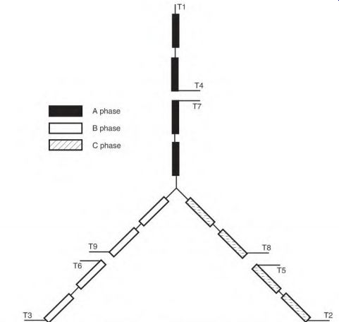
FIGURE 6.1 The four-pole nine-lead motor with two poles in each half of its
phase.
The connection schematic (Fig. 6.2) can be used as a guide for testing any nine-lead wye-connected motor. Identical length between numbers on a schematic means the data are the same, that is, T1 to T4, T2 to T5, T3 to T6, T7 to T8 and to T9. Identical circuits can be comparison-tested, which is an easy, reliable, and accurate method of checking a winding. Identical faults in each identical circuit (six total) are possible, but extremely remote.
Internally, a winding may have parallel wye circuits (Fig. 6.3). This reduces the winding's wire size. (Smaller wire is easier to form and insert into the slots.) Motors that are 5 horsepower and larger usually have multiple internal wye connections.
FIGURE 6.2 Using the nine-lead schematic to do the comparison test.
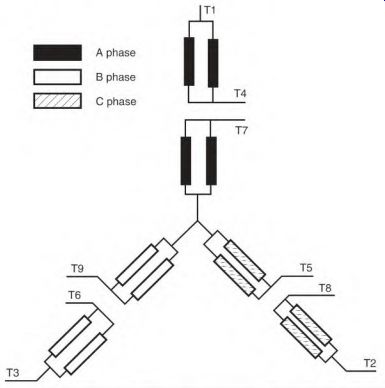
FIGURE 6.3 A four-pole two- and four-wye nine-lead motor.
If there is more than one internal wye connection, each half circuit will have one or more parallel circuits. An open circuit in a parallel connection (multi-wye) will show test results different from those of an open circuit in a one-wye connection (Fig. 6.4). Lead numbers T1 and T4 are the first half of the phase A circuit. Lead T7 starts the remaining half of the A-phase circuit and ends at the internal wye.
Lead numbers T2 and T5 are the first half of the phase C circuit. Lead T8 starts the remaining half of the C-phase circuit and ends at the internal wye.
Lead numbers T3 and T6 are the first half of the phase B circuit. Lead T9 starts the remaining half of the B-phase circuit and ends at the internal wye.
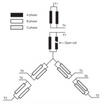
FIGURE 6.4 A four-pole four-wye nine-lead motor with an open circuit.
Leads T1 and T4, T2 and T5, and T3 and T6 have exactly the same data between them. Leads T7, T8, and T9 have twice as many turns (between them) as the three pairs have.
With the low-voltage (parallel) connection, line 1 connects to T1 and T7; line 2 to T2 and T8; and line 3 to T3 and T9. Leads T4, T5, and T6 are connected together and insulated, forming an external wye (Fig. 6.5). Leads T1, T2, and T3 have identical data to leads T7, T8, and T9.
With the high-voltage (series) connection, line 1 connects to T1, line 2 to T2, and line 3 to T3. Lead T4 connects to T7, T5 connects to T8, and T6 connects to T9. All are insulated separately (Fig. 6.6). The motor winding data are the same from line 1 to line 2, line 2 to line 3, and line 3 to line 1.
Current flow from line to line in a wye connection will pass through two complete phases (Fig. 6.7).
Understanding the Nine-Lead Delta Connection
The nine-lead delta-connected motor consists of three single-phase windings.
Each phase has identical turns, coils, and wire size. Each phase end is connected to the start of the next phase (Fig. 6.8).
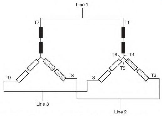
FIGURE 6.5 Low-voltage-connected nine-lead wye-connected motor.
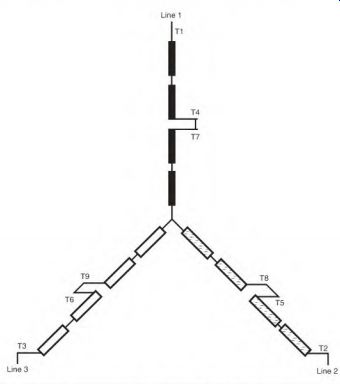
FIGURE 6.6 High-voltage-connected nine-lead wye-connected motor.
Each phase is separated into two equal circuits. The two circuits can be connected in series or parallel. The series connection is high voltage, and the parallel connection is low voltage. The high-voltage (series) connection will always be rated twice the low-voltage (parallel) rating.
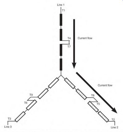
FIGURE 6.7 Current flows through two phases from L1 to L2.
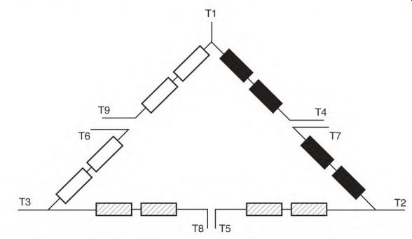
FIGURE 6.8 Nine-lead delta-connected motor.
FIGURE 6.9 Using the nine-lead delta schematic to test the motor's circuits.
The connection schematic (Fig. 6.9) can be used as a guide for testing any nine-lead delta-connected motor. Identical length between numbers means the data are identical between them, that is, T1 to T4 and to T9; T2 to T5 and to T7; and T3 to T6 and to T8. Identical circuits can be comparison-tested. Identical faults in each phase circuit (six circuits total) are possible, but extremely unlikely.
Smaller Wire Size with Delta and Multicircuit Winding
The delta-connected winding uses smaller wire than the wye connection.
Multiple internal circuits also use smaller wire than a single circuit. (Smaller wire is easier to form and insert into the slots.) The delta connection is usually found in 5-horsepower motors (and larger), but any size three-phase motor can be delta connected. The same is true of multiple-circuit connections. Internally, a winding can have many parallel circuits (Fig. 6.10). The dual-voltage (nine-lead) delta connection, with more than one internal delta circuit, is shown in Fig. 6.11. Each half circuit (for example, T1 to T4) has two parallel circuits.
The following list refers to the schematic in Fig. 6.12:
• Leads T1 and T4 are the first half of the phase A circuit. Lead T7 starts the remaining half of the A-phase circuit and ends at line 2 (T2).
• Leads T2 and T5 are the first half of the phase C circuit. Lead T8 starts the remaining half of the C-phase circuit and ends at line 3 (T3).
FIGURE 6.10 A four-circuit or four-delta connection.
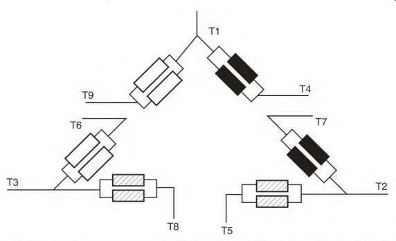
FIGURE 6.11 The nine-lead delta schematic with parallel internal connections.
• Leads T3 and T6 are the first half of the phase B circuit. Lead T9 starts the remaining half of the B-phase circuit and ends at line 1 (T1).
• Data between T1 and T4 are exactly the same as those between T1 and T9.
• Data between T2 and T5 are exactly the same as those between T2 and T7.
• Data between T3 and T6 are exactly the same as those between T3 and T8.
With the low-voltage (parallel) connection (Fig. 6.13), line 1 connects to T1, T7, and T6; line 2 to T2, T8, and T4; and line 3 to T3, T9, and T5.
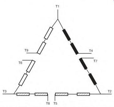
FIGURE 6.12 The nine-lead one- and two-delta connection.
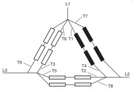
FIGURE 6.13 The nine-lead one- and two-delta connection for low voltage.
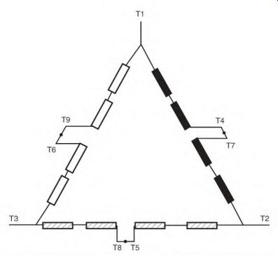
FIGURE 6.14 The nine-lead one- and two-delta connection for high voltage.
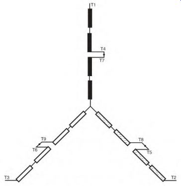
FIGURE 6.15 The nine-lead one- and two-wye connection for high voltage.
In the high-voltage connection (Fig. 6.14), line 1 connects to T1, line 2 to T2, and line 3 to T3. Lead T4 connects to T7; T5 to T8; T6 to T9; the three connections are insulated separately.
The number combination for high voltage is the same for both wye (Fig. 6.15) and delta. The data between line 1 and line 2, line 2 and line 3, and line 3 and line 1 are exactly the same in both high- and low-voltage connections.
Most of the current that flows from line 1 to line 2 (in a delta connection) will pass through one complete phase winding (Fig. 6.16). Some current will flow through the other two phases.
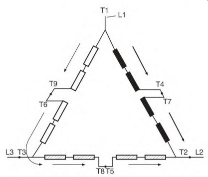
FIGURE 6.16 Current flow from L1 to L2 in the nine-lead delta-connected motor.
Identifying Unmarked Leads in a Nine-Lead Three-Phase Motor
Some methods of identifying unmarked leads require running the motor on part of its winding. Motors with concentric-shaped coils won't start themselves on part of their winding. The shaft has to be spun to start them, which is dangerous. Voltage readings must be taken from the leads with the motor running. (This is also dangerous.)
The following method is much safer and simpler. (Use the comparison test on all circuits to be sure there is no winding failure.)
Identifying Unmarked Leads in a Wye Connection
The following equipment is needed:
• Test light or ohmmeter
• Low-voltage DC source (6- or 12-volt battery)
• Low-scale DC voltmeter (must he analog)
• Numbered lead labels
The motor must be assembled (the rotor is needed to complete the magnetic circuit).
The first step is to separate the circuits by using an ohmmeter or test light. As can be seen in Fig. 6.17, there are three sets of two leads that light together and one set of three leads. Pair off the sets of two. Permanently label the leads in the set of three with numbers T7, T8, and T9 as shown.
Next, locate T1 and T4. Connect one of the DC voltage-source leads to T8, then make and break (flash) the circuit by intermittently touching the other lead to T9. Check across all three (two-lead) sets with the voltmeter while flashing T9. The voltmeter will show a strong deflection on two of the pairs and little or no deflection on one pair (Fig. 6.18). The pair with little or no deflection is T1 and T4-located but not identified-and is part of the T7 phase.
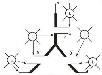
FIGURE 6.17 Identifying the circuits of a nine-lead wye-connected motor with
unmarked leads. The set with three leads is permanently labeled
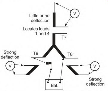
FIGURE 6.18 The battery connection for locating T1 and T4.
FIGURE 6.19 The connection for identifying T1 and T4.
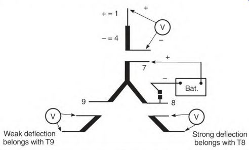
FIGURE 6.20 The battery connection for locating T2 and T5 and also T3 and
T6.
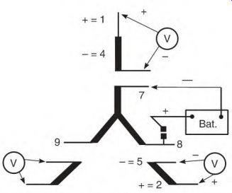
FIGURE 6.21 The connection for identifying T2 and T5.
Attach the voltmeter to the located pair. Attach the voltage source to T7 and T8 with the positive lead on T7 (Fig. 6.19). Flash the circuit. If the voltmeter deflects upscale, permanently label the motor lead that is connected to the positive voltmeter probe T1, and its paired lead T4.
With the voltage source still at this location (flashing T7 and T8), check the other two pairs with the voltmeter. The pair with a strong deflection will belong to T8, and the pair with little or no deflection to T9 (Fig. 6.20). Connect the voltmeter to the pair with a strong deflection (Fig. 6.21). Attach the voltage source to T7 and T8 (with the positive probe on T8). While flashing the circuit (if there is an upscale deflection), permanently label the motor lead connected to the positive voltmeter probe T2 and its paired lead T5.
Repeat the preceding procedure-with the positive probe of the voltage source on T9-to identify the last pair (T3 and T6). In the preceding test, two of the three phases had half of their windings energized, and one complete phase winding was idle. The pair of leads (belonging to the idle phase) had little or no deflection, because its winding wasn't in the same magnetic circuit (angle) as the energized phases. (The idle winding is offset 120 electrical degrees from the others.)
Identifying Unmarked Leads in a Delta Connection
This equipment is needed:
• Test light or ohmmeter
• Low-voltage DC source (6- or 12-volt battery)
• Low-scale DC voltmeter (must be analog)
• Numbered lead labels
The motor must be assembled because the rotor is needed to complete the magnetic circuit.
First, separate the circuits. As can be seen in Fig. 6.22, there are three sets of three leads that light to each other.
Next locate the center leads (delta points) of each circuit. (The points of the delta connection-leads T1, T2, and T3-often have larger wire than the other six leads.) Attach a DC voltage source to any two leads of any three- lead circuit. There will be a voltage from both voltage source leads-to the point-as shown in Fig. 6.23, if the right leads are selected.
FIGURE 6.22 Identifying the circuits of a nine-lead delta-connected motor
with unmarked leads.
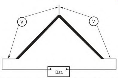
FIGURE 6.23 The connection for identifying the points T1, T2, and T3 of the
delta connection.
If the point is one of the leads attached to the power source, there will be a voltage read from one source lead to the idle lead and none from the other source lead (Fig. 6.24). Permanently label the delta points T1, T2, and T3.
Twist the two leads that belong to point T1 together, and apply intermittent DC voltage, as shown in Fig. 6.25. From point T2, one lead (of its three-lead circuit) will show a strong deflection, and the other lead will ...
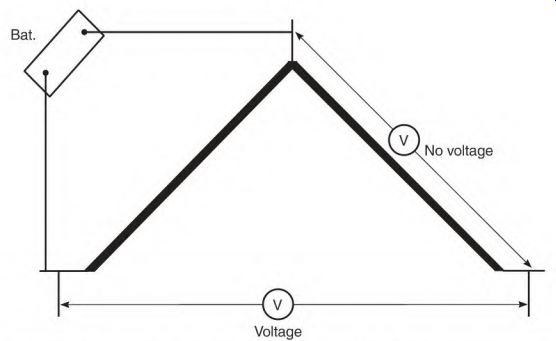
FIGURE 6.24 If the wrong pair is energized, one lead will have no voltage.
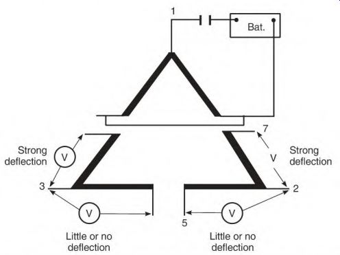
FIGURE 6.25 Power applied to Ti and its internally connected pair identifies
T7 and T5.
... show little or no deflection. Permanently label the strong deflection lead T7 and the other T5.
From point T3 (Fig. 6.26), one lead (of its three-lead circuit) will show a strong deflection, and the other lead will show little to none. Permanently label the strong deflection lead T6 and the other T8.
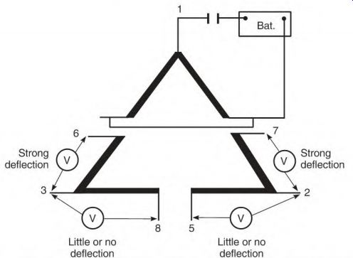
FIGURE 6.26 The voltmeter connection for identifying T8 and T6 and T5 and
T7.
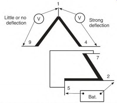
FIGURE 6.27 The connection for identifying T4 and T9.
Connect leads T5 and T7 as shown in Fig. 6.27 and apply intermittent DC.
From point T1, one lead (of its three-lead circuit) will show a strong deflection, and the other lead will show little or none. Permanently label the strong deflection lead T4 and the other T9.
Identifying unmarked leads with the delta connection involves deflection of the voltmeter needle-not polarity as with wye. Half of the two phases that are energized in this procedure are idle. Their windings are cut by the lines of force of the energized half. This produces a strong deflection.
The windings of the idle phase are out of the magnetic circuit and aren't cut by lines of force. Very little or no voltage is transformed into them.
Theory of Unmarked Lead Test
An explanation of the unmarked lead test involves magnetic circuits and transformer theory. Figure 6.28 shows a single-phase magnetic circuit containing four poles.
When half the poles are energized with intermittent DC, two more poles are created in the motor's iron core. The magnetic lines of force of these poles will cut the conductors of the idle poles as shown.
Power is transformed into the idle pole's coils, making it a transformer secondary. An analog DC voltmeter (attached to the idle pole's leads) will show a deflection. (A digital voltmeter reacts too fast and won't show the correct polarity.)
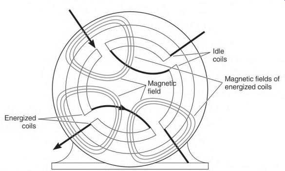
FIGURE 6.28 The magnetic circuit that develops in the stator iron (when half
of a phase is energized). The magnetic fields of the energized coils cut the
wires of the idle coils, transforming a low voltage into them.
The deflection in the idle half of the winding is strong, because it's in the same magnetic circuit (or angle) as the half that's intermittently energized.
In a three-phase stator, two phases are energized. The third phase is not in the magnetic circuit of the energized phases, and has very little voltage transformed into it.
Typical Winding Problems
It's very important to accurately identify problems that require a motor's removal and replacement. Winding problems that are identified should be documented. A history" of the plant's motor problems (on computer software) will point out problem areas that can be improved, or even eliminated.
These winding problems may be found in a three-phase motor:
• Shorted turns
• Ground (winding shorted to frame)
• Phase-to-phase short
• Open winding
• Burned windings from operating on single phase
• Submerged motor
• Assorted rotor problems
These problems require replacing or rewinding the motor.
Shorted Turns
A short is a common winding breakdown, and it requires rewinding or replacing the motor. Shorted turns are caused by nicked coil wire, high- voltage spikes, conductive contaminants, overheated winding, aged insulation, and loose, vibrating coil wires.
As explained under "Inductive Reactance" in Section 3, most of the resistance to current flow in an AC motor is furnished by inductive reactance. The resistance of the wire in a complete phase is a very small percentage of the motor's total impedance (resistance plus inductive reactance). Inductive reactance makes each turn very significant in the motor's ampere demand. Each turn supplies much more inductive reactance than resistance.
A short forms when one or more turns of a coil are bypassed because of an insulation breakdown between wires. The resistance that the shorted turns develop is eliminated from its phase winding, resulting in increased amperes.
When there are a few shorted turns in one of the three phases, a closed-loop circuit is formed by the turns within the short. As the motor runs, lines of force (from AC current flow) cut the wires in the closed-loop circuit. A high circulating current is transformed into the loop (Fig. 6.29a). Power consumed by the circulating current increases the amperes of the faulty phase, making it easy to identify the problem.
Circulating current in the closed loop often melts the circuit open. When this happens, the circulating current and the turns within the closed loop are eliminated (Fig. 6.29b). Only the resistance of the wire (turns) within the closed loop is now eliminated from the phase winding. Without the ampere demand of the circulating current, the difference lessens between the amperes of the faulty phase and those of the normal phases. A very small difference in resistance is all that is needed to identify the faulty phase. (The rotor should be turned during this test to eliminate its effect.)
Shorted turns in any AC winding are usually visible. They become charred quickly from the high circulating current that is transformed into them (Fig. 6.30).
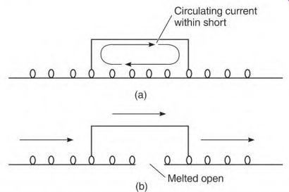
FIGURE 6.29 (a) Transformed current flow in the turns within a shorted coil
(closed loop) raises the amperes of the phase, (h) Closed loop melted open.
Ground
When a motor is "grounded," the winding is shorted either to the laminated core or to the motor's frame. The problem is usually found in a slot, where the slot insulation has broken down. Water is the most common cause of a grounded winding. A solid ground requires rewinding or replacing the motor.
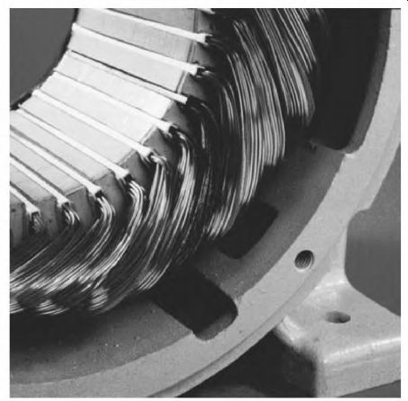
FIGURE 6.30 A shorted coil. EASA.
Some causes of slot insulation breakdowns are overheating, conducting contaminants, lightning, age, pressure of a tight coil fit, hot spots caused by lamination damage (from a previous winding failure), and excessive coil movement. Excessive coil movement is often caused by thermal growth and/ or coil twisting torque, brought on by reversing (plugging) or a momentary power interruption.
Phase-to-Phase Short
A phase-to-phase short is caused by insulation breakdown at the coil ends or in the slots. This type of fault requires rewinding or replacing the motor.
Voltage between phases can be very high. When a short occurs, a large amount of winding is bypassed. Both phase windings are usually melted open, so the problem is easily detected.
Among the causes of interphase breakdown are contaminants, tight fit (in the slot), age, mechanical damage, and high-voltage spikes.
Coils that form the poles for each phase are placed on top of each other in all three-phase motors. Figure 6.31 is a concentric-type winding. The coils don't share the slots with other poles in some concentric-type windings.
Figure 6.32 is the lap-winding type. The ends of the coils are nested within each other and have phase insulation between the poles. The coils usually share the slots with other poles. Insulation also separates the coils of each phase in the slots.
Some motors (up to 5 horsepower) are wound with no insulation separating the phases. Phase-to-phase insulation is important because there is a line voltage potential between phases regardless of a motor's horsepower.
Figure 6.33 is an end coil phase-to-phase short.
A phase-to-phase short occurs in the slot more often than at the coil ends. When a breakdown occurs in the slot, copper usually melts and fuses to the slot laminations. This copper has to be ground out and removed before the motor is rewound, or it becomes a hot spot and deteriorates the new insulation.
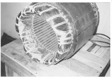
FIGURE 6.31 Windings of a concentric-wound stator. Electrom Instruments.
FIGURE 6.32 Windings of a lap-wound stator. EASA.
FIGURE 6.33 Winding with a phase-to-phase short. EASA.
Open Winding
A common cause of an open winding is undersized lead lugs. (See "Motor Lead Connecting Lugs," later in the section.) Charred connections in the motor's connection box are a sure indication of this problem.
Open windings are also caused by shorted turns, phase-to-phase shorts, ground-to-frame shorts, faulty internal coil-to-coil connections, severe overloads, and physically damaged coils. These faults require rewinding or replacing the motor.
An open winding will show several different symptoms (depending on the motor's internal connection). A wye-connected motor with an open winding will test differently from a delta-connected motor.
An open single-circuit winding will be "single-phased." Its power will drop to about half, and the motor won't start.
If the motor's internal connection is multicircuit, it will start but will have reduced power. An open circuit will cause the magnetic circuit to be unbalanced. Under normal load the motor will run more slowly--and will overheat. A micro-ohmmeter is used to identify this problem.
A motor with a high number of parallel circuits, that is, four and eight wye, will show less power loss when one circuit is open. Multi-parallel circuit connections are used in motors above 5 horsepower.
The windings of a severely overloaded motor (operating on 250 volts) usually become completely charred before an open winding occurs. An overloaded motor operating on 440 volts, however, often will have no sign of burned wires before its windings melt open. In either case, the overload protection isn't working, and the motor should be rewound or replaced.
Burned Windings from Operating on Single Phase
When one line of a three-phase power supply opens, the power becomes single phase. If this happens while the motor is running, its power output is cut approximately in half. It will continue to run, but it can no longer start by itself. Like a single-phase motor without its start winding energized, it has no rotating magnetic field to get it started.
Single-Phase Damage to a Wye-Connected Nine-Lead Motor
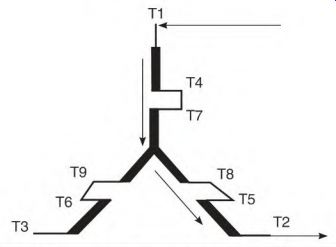
FIGURE 6.34 Schematic showing where the current flows in a wye-connected motor
with line 3 open (single phase).
Figure 6.34 shows the current path through the W5^e connection. Two phases of the windings are energized; the third phase has no current flow. If the motor's protection device doesn't function, the two phases that carry current will overheat and char. The phase without current flow will look normal. Figure 6.35 is a picture of a single-phase-caused burnout in a four-pole winding.
FIGURE 6.35 A wye-connected motor that failed because of a single-phase condition.
Line 3 is open. EASA.
Single-Phase Damage to a Delta-Connected Nine-Lead Motor
Figure 6.36 shows the current path through the delta connection, with an open phase. The A phase has extremely high current flowing through it. The other two phases have about half as much. The phase with high current will overheat and char if the motor's protection device doesn't disconnect it. The phases that carry less current will look normal. Figure 6.37 is a picture of a single-phase-caused burnout in a four-pole winding.
Submerged Motor
If a three-phase motor has been submerged in water but not energized, there's a good chance it won't need rewinding or replacing. Cleaning and baking the windings may be all that's needed.
The motor should be disassembled as soon as possible. If the motor has ball bearings, they should be replaced. If it has sleeve bearings, the oil wicking material will pit or rust the shaft area located in the bearing window.
Replace the oil wick material immediately. If the motor has an oil reservoir and oil ring, the reservoir should be thoroughly cleaned.
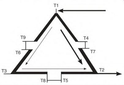
FIGURE 6.36 Schematic showing where the current flows in a delta-connected
motor with line 3 open (single phase).
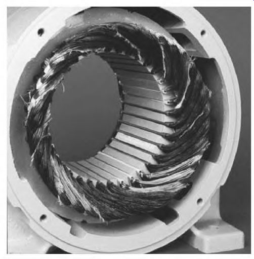
FIGURE 6.37 A delta-connected motor that failed because of a single-phase
condition. Line 3 is open. EASA.
The windings should be first tested with an ohmmeter. (A wet winding should never be subjected to a test voltage that could arc through the wet slot insulation.) The baking temperature shouldn't exceed 200 F. The ohmmeter test should read infinity after baking. After the windings have been cleaned, dried, and tested, they will need a coat of air-drying varnish.
When water soaks the slot insulation, the copper windings and the core become a form of battery. A small voltage can be read (with a millivoltmeter) between the winding and the frame when the slot insulation is wet. A zero reading indicates the motor has been baked long enough.
A megohmmeter, hi-pot, or surge tester can be used when an ohmmeter test shows infinity.
Assorted Rotor Problems
This is a review of the rotor problems found in Section 3, with more detailed information:
• Open rotor bars
• Open end rings
• Misaligned rotor/stator iron
• Rotor dragging on the stator
• Rotor loose on shaft
Open Rotor Bars
Open rotor bars or end rings usually necessitate replacing the motor. They can be repaired, recast, or re-barred (if it's economical). (It's important that any replaced metal be the same as the original.) Open rotor bars are caused by overload burnout, arcing in the slot from a shorted winding, loose bar vibration, thermal growth stress (from starting), flaws in bar material (casting flaw), and poor connections with end rings.
Open rotor bars cause loss of power. If too many rotor bars are open, a loaded motor will draw amperes high enough to open its protection device.
With no load, the amperes will be very low. Slow starting and lower-than- rated RPM are a sign of broken rotor bars.
Open End Rings
Open end rings cause uneven torque and some power loss. A ring with one open spot will soon develop more open spots. Each time the open spot crosses a 90° spot between poles, the current will double in the ring area between the next two poles (Fig. 6.38). Causes of open end rings and/or cracked end rings include flawed casting; motor burned out from overload; motor redesigned for a higher speed (without increased size of end ring); ring material drilled away for balancing; thermal growth stress; and mechanical damage.
A bubble or void in an end ring can cause an electrical vibration. (This type of vibration can't be corrected by balancing.) It can be detected by cutting the power and allowing the motor to coast. Electrically caused vibrations will always cease as soon as the power is shut off.
Lines of flux
Lines of flux
Current will double here
Cracked end ring

FIGURE 6.38 Current flow in a squirrel cage rotor with an open-end ring.
Misaligned Rotor/Stator Iron
A motor with a misaligned rotor will draw high amperes and will lose power.
The magnetic path becomes distorted, causing the magnetizing amperes to increase. The stator windings will char and resemble an overload burnout.
Possible causes of a misaligned rotor include:
• Wrong bearing shim placement
• Bearings not installed correctly on the shaft (extended race on wrong side)
• Wrong bearing width
• Captive bearing not held as originally placed
• End bells interchanged
• Stator core shifted on its shell
• A rotor shifted on its shaft
• A rotor replaced with a shorter rotor.
A rotor with the same diameter but longer than the original will work, but some efficiency is lost.
Rotor Dragging on the Stator
If the rotor drags on the stator and the bearings aren't worn, it's common practice to "skim" the rotor on a lathe. The process increases the air gap, which increases the no-load amperes. The increased amperes are similar to a misaligned rotor and stator iron. The magnetic circuit is degraded, so it takes more amperes to magnetize the motor's iron. The motor will run hotter than normal, because the motor is drawing more magnetizing amperes. If the load is at maximum or there are any adverse conditions (such as low voltage or frequent starts), the motor should be replaced. (There will be some permanent power and efficiency loss.)
Rotor Loose on Shaft
A loose rotor on a shaft makes a rumbling or vibrating sound. The sound will cease after the power is turned off (while the motor is coasting). If the motor has operated this way for very long, a red dust will form between the shaft and rotor iron. This dust is oxidized iron, caused by the rubbing action between the shaft and the rotor iron. (The same thing happens when a pulley or bearing is loose on a shaft.)
The decision to repair a loose rotor depends on the price of a replacement motor and the importance of the motor in the plant operation.
There are options for this problem: The rotor (and shaft) can be replaced; the rotor can be bored out and a new shaft fitted to it; or a thin metal wedge can be driven between the shaft and rotor to secure it.
Wedging the rotor may offset it enough to make it drag on the stator.
It would then be necessary to skim the rotor--on a lathe--to keep it from dragging. The rotor should be bored and fitted with a new shaft. In most cases, it is more economical to replace the motor.
When Motors Overheat
Overheating is a major cause of insulation and bearing failure. Causes of overheating include the following:
• Line
• Operator
• Control
• Motor fault
• Location
• Maintenance
Line-Caused Overheating
There are four causes of line-caused overheating: overvoltage, low voltage, unbalanced voltage, and a high-resistance connection.
Overvoltage
Overvoltage can cause a normally loaded motor to overheat. NEMA standard specifications allow motors a voltage deviation of ± 10 percent from their nameplate voltage rating.
All motors will start their load faster when voltage is high. T-frame motors, however, overheat (on overvoltage) more than the older U-frame or high-efficiency motors (even with less than 10 percent overvoltage). T-frame motors have smaller copper wire in their windings and significantly less iron in their core. (They depend on a high volume of air to keep them cool.) NEMA approved the T-frame motor's design in 1967. This downsized motor was made possible by the development of insulation that could tolerate higher temperature.
A big improvement in the T-frame design is the use of ball bearings instead of sleeve bearings. Ball bearings make it possible to have a closer fit between the rotor and the core, thus reducing the air gap. (Air gap reduces a motor's efficiency more than other forms of loss.) The induction motor and the transformer have very comparable characteristics-both transform power from one winding to another. Unlike a motor, a transformer has no air gap.
Therefore, some transformers have efficiency ratings above 99 percent.
Earlier T-frame motors had higher efficiency than U-frame motors, as less iron was used in the core and rotor. (Magnetizing more iron than necessary lowers the efficiency.) Design changes that improved the T-frame motor's efficiency included getting rid of excess iron and reducing the air gap.
However, because of the reduced overall size, there was a loss of area for heat dissipation.
Some motor manufacturers reduced material used in the electrical and mechanical components too much. (One manufacturer made fractional- horsepower motors that were too fragile to ship. The stator core was mounted in a very thin steel shell. Several dents were punched in the shell to hold it in place. The core was easily dislodged with only moderately rough handling.) Manufacturers increased the size of the motor's cooling fan and installed metal baffles to direct the air on the windings. Air volume was increased because of the extra heat created by undersized wire. (Power used to move the extra air reduces the motor's efficiency.) In one case, there were two motors (made by the same manufacturer) that had different horsepower ratings. They had identical core and rotor dimensions and identical electrical data. One motor was rated 0.5 horsepower and the other 0.5 horsepower. The 1/3-horsepower motor had a totally enclosed frame, and the 0.5 horsepower motor had an open frame. The nameplate RPM of the 1/2-horsepower motor was lower than that of the 1/2-horsepower motor.
By loading the motor down a few RPM, it produced 1/2 horsepower. Air flowing through the open end brackets increased the amount of cooling capability enough to compensate for the increased amperes and heat.
Low Voltage
Low voltage affects all motors in the same way-they lose power and may take too long to start a load. Prolonged starts cause excess heat in the stator winding (at the start of its duty cycle). Another concern with low voltage is the heat that develops from frequent starting.
Under maximum load, low voltage causes the motor to run more slowly than the nameplate RPM. Technically, it's overloaded. It will run hot and will soon fail.
If the service wire to a motor is too small, it causes low voltage (especially when starting). Some symptoms are frequently blown fuses or tripped protection devices. Voltage normally drops briefly from the motor's high starting current, but the voltage should come back up to nearly its full value as soon the motor reaches full speed. Although NEMA standards allow + 10 percent of nameplate voltage, the voltage should not drop more than 1 percent.
(The NEMA standard pertains to the motor's supply voltage, not the voltage drop.) High-efficiency motors draw higher starting current than standard motors. This may require an increase in the wire size of the feeder line.
Motors with a maximum load are the first to react to low voltage. A prime example was a motor that tripped its overload protector at a certain time of the day. The cause was traced to a high-ampere load coming online (elsewhere in the plant) at that time, lowering the voltage for the entire plant.
Power lines that are loaded nearly to their capacity can have intermittent low voltage. A brief high-load demand from another location will cause a voltage drop.
Power companies put capacitors across the lines to correct the low power factor. Inductance develops in power lines over a long distance. Lines are crossed at regular intervals to cancel the inductance. Over many miles, however, inductance still accumulates, requiring capacitors to do the final power factor adjustment. Low voltage will develop if the capacitors fail. A voltage recorder should be used if incoming power problems are suspected.
The recorder should be on long enough to include every load variation the location has.
Unbalanced Voltage
Unbalanced voltage has many sources:
• Failed power-factor-correcting capacitors can affect the voltage of an entire building.
• A high-resistance connection is a frequent cause of an unbalance. This problem can be easily spotted with infrared instruments.
• Unbalanced single-phase loading (such as lighting and single-phase motors) is a frequent cause of unbalanced voltage.
Lighting load can be balanced at the distribution panel. (A single-phase air conditioner is an example of a motor load that is hard to balance, due to the air conditioner's intermittent operation.) Unbalanced voltage will cause a motor to overheat even if it is lightly loaded. Motors are designed to have exactly the same number of turns in each phase. Unbalanced voltage is the same as taking turns from one phase and putting them into another. The result is unbalanced and conflicting magnetism. The distorted location and uneven magnitude of the poles (transformed into the rotor) create bucking magnetic flux and harmful harmonics.
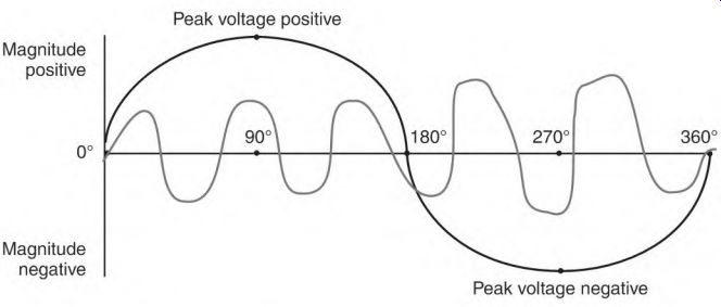
FIGURE 6.39 A harmonic voltage sine wave within a line voltage sine wave.
EASA.
Harmonics are a voltage within a voltage (Fig. 6.39). When the harmonic voltage is on the opposite side of the zero line (from the supply voltage), its value subtracts from the line voltage. This reduces the line voltage value but weakens the motor.
A winding failure caused by unbalanced voltage will have a definite appearance (as shown in Fig. 7.8 in the next section). In a wye-connected winding, one phase is charred, one is discolored (from excess heat), and the third phase isn't affected. A delta-connected winding will look similar to the wye-connected winding-two phases are overheated and one phase is unaffected.
Another cause of unbalanced voltage-related heating is worn contacts (in a motor starter) that don't make a solid connection.
High-Resistance Connection
A high-resistance connection is one of the more frequent causes of electric motor failure. Because of a motor's high starting current, its ampere load is very' different from most electrical loads. Every connection in the motor's supply circuit is subjected to a brief high-ampere stress when it starts. These connections should be checked regularly (more often if the motor starts frequently). The National Electric Code specifies wire size for a motor's supply line according to the motor's nameplate amperes. Most motors have inrush current many times their nameplate value (see "Code Letter" in Section 5). (Inrush current of high-efficiency motors is higher than that of standard motors.) Increasing the supply line wire size (one size above the code requirement) is a one-time cost that decreases the chance of motor failure.
Connecting Terminals
The connecting terminals in a disconnect switch and/or a motor control are common spots for high-resistance connections.
Heat expands the copper wire faster than it expands the control's terminal.
The terminal doesn't give, so the wire mashes and is distorted. This has an accumulating effect, loosening the connection slightly each time the motor starts. Eventually a high-resistance connection forms.
Disconnect and control connections should be routinely checked and tightened. A small infrared gun can be used to check connections. All connections should be the same temperature.
Aluminum wire has a notorious reputation for developing loose connections. Its use is not recommended for an electric motor load.
Motor Lead Connecting Lugs
Motor lead lugs should be thick enough (throughout the connection) to represent the circular mil area (size) of the motor's lead wire. If any part of the lug is too small, it becomes a resistor in series with the motor, and current will be restricted when the motor needs it the most-to start the load.
Figure 6.40 shows lugs that aren't made for electric motors. Lug (a) is a piece of copper tubing, which has been partially flattened and has a hole punched in it for the connecting bolt. Its ferrule will hold wire that has a much greater circular mil area than that of the bolted part of the lug. Lug (b) is clearly not a motor duty lug.
Motor Lead Wire Size
Some motor manufacturers size the lead wire according to the motor's nameplate amperes. The wire has high-temperature insulation (usually white) and coarse, tinned strands. When installing lugs on this wire, be sure to include all the strands. One strand represents a high percentage of the wire's (inadequate) total circular mil area.
When an electric motor repair center installs lead wire, the wire is equal to or larger than the total circular mil area of all the internal coil wires that are attached to it. Internal coil connections are twisted together and silver-soldered. The soldered part of the connection joins more circular mil area than that of the coil wires. (This is the last place to get hot from high current.)
Operator-Caused Overheating
Operators often cause motors to overheat. If paid by the unit, operators often overload the machine. The mining industry is a case in point.
An overloaded induction motor can be quickly checked with a tachometer. Compare the tachometer reading with the motor's nameplate.
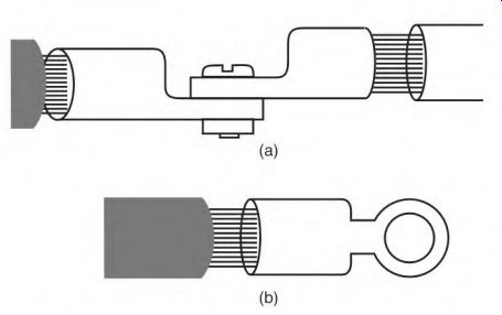
FIGURE 6.40 Two lead lugs that can cause motor failure.
Just a few RPM slower than the nameplate RPM will cause overheating.
The design A (or a high-efficiency) motor will run hotter than a standard induction motor under this condition. This can be seen in the torque curve that the design A motor develops near its full-load speed (Fig. 6.41). Frequent starting and stopping often causes excessive heating in motors above 25 horsepower. The physical mass of a large motor doesn't dissipate heat easily.
Most motors will cool better while running with no load than when shut off. If a motor is required to start often, forced ventilation or the use of a clutch should be considered if motor failure is frequent.
An abrupt speed change is harmful to all motors, but especially to brush-type (DC and wound-rotor three-phase) motors. The design D induction motor should be considered if its torque curve is compatible with the load requirement.
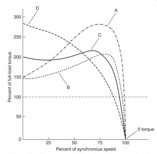
FIGURE 6.41 The design letter table used for choosing a motor to lit the load's
torque demands.
Control-Caused Overheating
Duty-cycle loading requirements (that cause overheating) can be relieved by forced ventilation. Some conditions helped by forced ventilation are overheating from prolonged slow speed at maximum torque, frequent start- stop cycle, and a duty cycle that includes overloading for a short time before shutdown. Operating a motor for a time with no load will cool the winding and core uniformly. Running with no load on reduced voltage is an even better way to cool a motor.
The part-winding start method (of starting a motor) isn't recommended for frequent starting. Part of the winding (one-half or two-thirds) starts the load and will heat excessively when started frequently. Switching from part winding to full winding too slowly (over 3 seconds) will also overheat the motor.
FIGURE 6.42 A motor with concentric-shaped coils won't start using the part- winding start method. However, it will start with lap-shaped coils.
If the motor has concentric-wound coils, it won't start on part of its winding. Figure 6.42 compares the concentric- and lap-shaped coils.
This motor needs a special internal connection before it can be used on a part-winding start control. Many motors (up to 300 horsepower) use the concentric type of winding. When an old part-winding start motor is replaced, the new motor must be designed for this starting method.
A poorly designed variable-hertz control can cause a motor to overheat.
(Voltage should change with the hertz change.) Not all motors are suited for variable-hertz drives. In many cases, older T-frame motors have not worked as well as high-efficiency motors or U-frame motors on variable hertz.
If a motor is labeled inverter duty (variable-hertz duty), it doesn't mean the motor is designed for slow speed at maximum torque or any other extreme deviation from the motor's speed. Inverter duty means the motor's coil wire has special insulation. This insulation postpones breakdown from voltage spikes caused by abrupt voltage and current changes. It does not prevent breakdown. Reactors, filters, or surge capacitors should be installed to reduce this problem.
Heat Developing from Reduced-Power Starting
The amount of internal heat a motor accumulates in across-the-line starting compares to that produced in the wye-delta or reduced-voltage starting methods. Any reduced-power starting method that applies all the motor's winding is better for the motor than a part-winding start method.
Reducing the motor's starting amperes lessens the amount of voltage drop caused by across-the-line starting. In some cases, reduced-power starting is done to protect a load that is sensitive to quick starts.
If a load that requires frequent starting causes the motor to heat excessively, forced ventilation will lengthen a motor's insulation life. Ventilation should continue for a time after the motor is offline. (The amount of time required depends on the motor's size, etc.).
For maximum motor life, it's best to start a large motor with no load. (A clutch can be used to apply the load after the motor has reached full speed.)
Motor Fault Overheating
Shorted Turns
Shorted turns in a winding will cause overheating. When just a few coil turns are shorted, they form a closed loop. A circulating current is transformed into the loop. The current is usually high enough to melt a wire, opening the closed loop.
Before this happens, a pole forms from the circulating current in the shorted turns. This pole doesn't conform to the surrounding poles. Its magnetism causes a ringing sound, unique to motors with shorted turns.
Shorted turns may not slow the motor at all. A line-to-line ampere comparison will show a substantial difference between motor leads, and will identify the problem as shorted turns.
Ground in Winding
If a winding is grounded (shorted) to the stator or frame, it will get hot (from the increased ampere flow). This condition usually causes a fuse or breaker to open. If there are enough coils in the motor's circuitry between the line and the ground, the motor will still run, but with increased (and unbalanced) amperes.
Worn Bearings and Uneven Air Gap
Worn sleeve bearings cause overheating. A three-phase motor's torque is so smooth that it may be necessary to move the shaft to detect a worn sleeve bearing. It's common for a rotor to drag on the stator before the problem is detected.
Uneven air gap from worn sleeve bearings will cause internal heating in some motors. Motors that use an internal circuit connection (that balances the current path through the poles) are less affected by uneven air gap.
Although uneven air gap should be avoided, it won't cause immediate damage to a motor's winding. In the past, most three-phase motors had sleeve bearings. Many ran for years with worn bearings and an uneven air gap-with no electrical problems.
Wrong Service Factor
The service factor (found on the motor's nameplate) is the amount of overload a motor can handle (without overheating) for a limited time. The service factor number is a multiplier. The multiplier number times the motor's nameplate amperes is the amount of overload a motor can handle. Service factor numbers are 1, 1.15, and 1.2.
A high service factor usually indicates a well-designed motor. A totally enclosed motor will have a service factor of 1, meaning it can't be loaded higher than nameplate amperes.
Many air compressors are deliberately designed to use the service factor.
(They are in a highly competitive market.)
In one case, an air compressor had a 75-horsepower motor with a 1.2 service factor. The compressor was designed to use the full 1.2 service factor value. (When a compressor operates normally, it will cycle for a time unloaded so the motor has time to cool down.) Unfortunately, this motor never ran unloaded because the air volume demand was so high. The motor failed after a few months.
Connected for the Wrong Voltage
If a dual-voltage motor connected for high voltage is connected to low voltage, it will produce only one-fourth of its rated horsepower. It will start much more slowly than normal. Some loads allow this motor to reach nearly normal speed. If an induction motor's RPM is below its nameplate rating, the high slip will cause it to overheat.
If a dual-voltage motor connected for low voltage is connected to high voltage, the results with any type of load are immediate. The motor develops many times its normal starting torque, and it draws so many amperes that its winding is destroyed in a matter of seconds. NEMA standards allow + 10 percent of nameplate voltage. If a fully loaded motor, rated for 220 volts, is connected to 250 volts, it will run hotter than normal (a 12 percent difference). Motors with frequent start cycles will have extreme overheating problems when voltage is this high.
A motor rated for 208 volts but connected to 250 volts will overheat without a load. (The connection is 20 percent over its rated voltage.) A motor rated for 250 volts but connected to 208 volts can't pull its rated load. It may not start a load requiring high breakaway torque. The motor will work if the load is reduced. (A tachometer should be used to make sure the RPM isn't below the nameplate rating.) Any departure from rated voltage greater than +10 percent will result in extra heat.
Wrong Hertz
Motors designed for 50 Hz power most of the machinery manufactured in Europe. Problems can occur when this machinery is used in the United States on 60 Hz. A four-pole 50-Hz motor runs 300 RPM faster on 60 Hz.
The motor will be overloaded if its load is air or liquid. Conveyer belts and augers will also overload this motor. (Changing the pulley dimension ratio solves the problem for some applications.) Direct-driven loads require major redesigning or replacement.
In one case, the power for an entire facility was converted to 50 Hz, because so much of the equipment used 50 Hz. When failed motors were replaced with 60-Hz motors, they ran hotter than normal on 50 Hz. (The 60-Hz motors have fewer turns per pole than 50-Hz motors.) If the supply voltage is lowered for the 60-Hz motors, they won't run as hot, but power output is lessened.
Internal Motor Problems
Internal motor problems can cause overheating. The problems that follow were covered earlier, under "Assorted Rotor Problems," but are reviewed here briefly.
Rotor/Stator Alignment
If the rotor and stator iron aren't aligned properly, the result is high amperes (loaded or no load) and loss of power. This problem can't be detected with an ohmmeter, or limited current and turning of the shaft.
Open Rotor Bars
Open rotor bars cause power loss. With a normal load, the rotor will run more slowly than the nameplate RPM, resulting in high amperes in both the rotor and the stator windings. (Too much slip increases rotor hertz, which causes higher amperes.)
Cracked End Ring
Cracked end rings cause uneven torque and loss of power. The result is similar to that of open rotor bars.
Air Gap Too Large
If the rotor becomes "out of round," it may drag on the stator core. This condition is corrected by skimming some of the iron off the rotor with a lathe.
Skimming the rotor increases the air gap. Air gap should be kept at a minimum because it's a break in the magnetic circuit. A large air gap creates a large increase in the motor's magnetizing amperes. The motor will run hotter, and there will be a slight power and efficiency loss.
Whether to skim the rotor should be decided on a case-by-case basis.
If the motor has more power than needed or its duty (frequent starts, etc.) doesn't cause above-normal heating, skimming the rotor does no harm.
A large air gap can be similar to a misaligned rotor. (It can't be detected with an ohmmeter, or limited current and turning of the shaft.)
Location-Caused Overheating
In a hot location, the surrounding air increases a motor's normal running temperature. If the motor is loaded near its capacity, it will overheat. Even forced ventilation may not help.
If a motor is located too close to a wall or if anything impedes its intake or exhaust airflow, it can overheat (depending on ambient temperature). The recommended clearance is 18 inches on all sides.
Intense sunlight can cause a maximum-loaded motor (or a motor that starts frequently) to overheat.
An enclosure added for protection from the weather can be harmful to a motor, because air movement is restricted. In addition, the enclosure may trap the motor's hot air exhaust. An exhaust fan is often added to remove the hot air from the enclosure. However, forced air movement shouldn't affect the motor's normal air movement.
Maintenance-Caused Overheating Belts Too Tight
Extra stress is put on bearings if the belts are too tight. If the motor has a long stator, the shaft may bow and misalign the bearing's inner race. There have been cases where the rotor dragged on the stator core (because of overly tightened belts).
Pulley Problems
A replacement pulley that is slightly larger than the original can overload a motor if the load increases with a speed increase.
A worn pulley may make it necessary to tighten the v-belts excessively (to keep them from slipping). (The motor drive pulley is always the one that wears first.)
Section 6 Review
1. The dual-voltage nine-lead three-phase motor will be connected (internally) either wye or delta (75). T F
2. In-plant power problems will cause immediate motor failures (75). T F
3. Name two in-plant problems that will cause the immediate failure of a three-phase motor (75).
4. The ends of each phase are joined internally in a wye-connected motor.
(275-276) T F
5. The delta connection has each phase end connected to the start of the next phase (278-281). T F
6. The delta connection and multicircuit design allow the use of smaller wire in the winding coils (281-283). T F
7. Why should the motor be assembled when identifying unmarked leads (285-286)?
8. Why is there no voltage detected in the idle phase during the unmarked lead test (285-288)?
9. The delta connection will have three sets of three leads that light to each other (88). T F
10. When testing for unmarked leads, an analog DC voltmeter shows a deflection, and works better than a digital meter (292-293). T F
11. The largest amount of resistance to current flow in a three-phase winding is furnished by inductive reactance (293-294). T F
12. Circulating current within a short can char and melt the turns within the short (94). T F
13. A phase-to-phase short is usually obvious, and requires replacing or rewinding the motor (295-296). T F
14. Name three causes of an open winding (98).
15. A three-phase motor running on single phase will have (98)
a. full power.
b. 2/3 power.
c. 1/2 power.
16. A motor that failed from a single-phase line condition-with one phase burned and two phases near normal-is connected (00)
a. wye.
b. delta.
17. The first test (from winding to frame) on motors that have been subjected to water should be done with an ohmmeter (00). T F
18. All motors that have been submerged in water must be rewound (300-301). T F
19. An ohmmeter will always detect a grounded motor winding by testing at the motor's disconnect or control (01). T F
20. All rotor problems cause instant motor failure (02). T F
21. A sign of misaligned rotor/stator iron is high no-load amperes (03). T F
22. What is an easy way to detect electrically caused vibration (303-304)?
23. An out-of-round rotor that has been "skimmed" with a lathe has no effect on a motor's performance (03). T F
24. A rotor that is loose on its shaft should be replaced (303-304). T F
25. Overvoltage will affect some motors more than others (304-305). T F
26. What is the allowable NEMA standard deviation (304-305)?
27. Most of a motor's efficiency loss is in the air gap (05). T F
28. Within the allowable 10 percent voltage variation, low voltage overheats a (fully loaded) motor more than high voltage does (305-306). T F
29. Operating on low voltage is similar to overloading a normally loaded motor (06). T F
30. Unbalanced voltage is always caused by a faulty transformer, and is a problem the power supplier has to fix (306-308). T F
31. Unbalanced voltage will cause immediate winding failure in a three- phase motor (07). T F
32. Unbalanced voltage affects only wye-connected motors (08). T F
33. High-resistance connections occur more often in a motor supply line than in that of a lighting circuit (08). T F
34. Frequent motor starting increases terminal connection problems (08). T F
35. A motor that has oversized supply lines can't be protected from overloads (08). T F
36. Tightening the terminals in a motor's disconnect switch should be part of the scheduled motor maintenance (08). T F
37. Motor lead lugs and lead wire can be undersized because they carry current such a small distance (308-309). T F
38. Undersized lead lugs will eventually overheat and char, causing an open or high-resistance circuit (09). T F
39. A tachometer can quickly determine if a motor is overloaded (309-310). T F
40. If a motor overheats because of its stop/start cycle, but not its load, it's better to install a larger motor than to use forced ventilation (10). T F
41. Running a motor with no load is the best way to uniformly cool down a motor (11). T F
42. Across-the-line starting and reduced-power starting produce approximately the same amount of internal heat (12). T F
43. A motor run with shorted turns in its winding (312-313).
a. may
b. won't
44. Shorted turns can sometimes be detected by a ringing sound (312-313). T F
45. An uneven air gap will destroy a winding immediately (13). T F
46. A motor with a high service factor can run continuously at this value (13). T F
47. If a motor connected for high voltage is run on low voltage, it will produce only half its rated horsepower (14). T F
48. A motor rated for 250 volts can operate on 208 volts if its full-load speed is close to its nameplate RPM (14). T F
49. A four-pole motor designed for 50 Hz-operating on 60 Hz-will run 300 RPM (314-315)
a. faster.
b. slower.
50. A 50-Hz motor has on 60 Hz (314-315).
a. more power
b. less power 51. A 60-Hz motor has on 50 Hz (15).
a. more power
b. less power 52. All rotor problems cause a fully loaded motor to lose power and run hot (15). T F
53. Most large motors need 18 inches of clearance, for unrestricted ventilation (16). T F