AMAZON multi-meters discounts AMAZON oscilloscope discounts
OBJECTIVES
• explain the operation of an instrument potential transformer.
• explain the operation of an instrument current transformer.
• diagram the connections for a potential transformer and a current transformer in a single-phase circuit.
• state how the following quantities are determined for a single-phase circuit containing instrument transformers: primary current, primary voltage, primary power, apparent power, and power factor.
• describe the connection of instrument transformers in a three-phase, three-wire circuit.
• describe the connection of instrument transformers to a three-phase, four-wire system.
Instrument transformers are used in the measurement and control of alternating cur rent circuits. Direct measurement of high voltage or heavy currents involves large and expensive instruments, relays, and other circuit components of many designs. The use of instrument transformers, however, makes it possible to use relatively small and inexpensive instruments and control devices of standardized designs. Instrument transformers also protect the operator, the measuring devices, and the control equipment from the dangers of high voltage. The use of instrument transformers results in increased safety, accuracy, and convenience.
There are two distinct classes of instrument transformers: the instrument potential transformer and the instrument current transformer. (The word “instrument” is usually omitted for brevity.)
POTENTIAL TRANSFORMERS
The potential transformer operates on the same principle as a power or distribution transformer. The main difference is that the capacity of a potential transformer is small compared to that of power transformers. Potential transformers have ratings from 100 to 500 volt-amperes (VA). The low-voltage side is usually wound for 115 volts or 120 volts. The load on the low-voltage side usually consists of the potential coils of various instruments, but may also include the potential coils of relays and other control equipment. In general, the load is relatively light and it's not necessary to have potential transformers with a capacity greater than 100 to 500 volt-amperes.
The high-voltage primary winding of a potential transformer has the same voltage rating as the primary circuit. When it's necessary to measure the voltage of a 4,600-volt, single-phase line, the primary of the potential transformer would be rated at 4,600 volts and the low-voltage secondary would be rated at 115 volts. The ratio between the primary and secondary windings is:
4,600/115 or 40/1
A voltmeter connected across the secondary of the potential transformer indicates a value of 115 volts. To determine the actual voltage on the high-voltage circuit, the instrument reading of 115 volts must be multiplied by 40. (115 x 40 = 4,600 volts). In most cases, the voltmeter is calibrated to indicate the actual value of voltage on the primary side. As a result, the operator isn't required to apply the multiplier to the instrument reading, and the possibility of errors is reduced.
ill 22-1 illustrates the connections for a potential transformer with a 4,600-volt primary input and a 115-volt output to the voltmeter. This potential transformer has subtractive polarity. (All instrument potential transformers now manufactured have subtractive polarity.) One of the secondary leads of the transformer in figure 22-1 is grounded to eliminate high-voltage hazards.
Potential transformers have highly accurate ratios between the primary and secondary voltage values; generally the error is less than 0.5 percent. Power transformers are not designed for highly accurate voltage transformation.
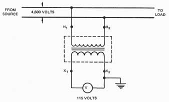
ill. 22-1 Connections for a potential transformer
CURRENT TRANSFORMERS
Current transformers are used so that ammeters and the current coils of other instruments and relays need not be connected directly to high-current lines. In other words, these instruments and relays are insulated from high currents. Current transformers also step down the current to a known ratio. The use of current transformers means that relatively small and accurate instruments, relays, and control devices of standardized design can be used in circuits.
The current transformer has separate primary and secondary windings. The primary winding, which may consist of a few turns of heavy wire wound on a laminated iron core, is connected in series with one of the line wires. The secondary winding consists of a greater number of turns of a smaller size of wire. The primary and secondary windings are wound on the same core.
The current rating of the primary winding of a current transformer is determined by the maximum value of the load current. The secondary winding is rated at 5 amperes regardless of the current rating of the primary windings.
E.g., assume that the current rating of the primary winding of a current transformer is 100 amperes. The primary winding has three turns and the secondary winding has 60 turns. The secondary winding has the standard current rating of 5 amperes; therefore, the ratio between the primary and secondary currents is 100/5 or 20 to 1. The primary current is 20 times greater than the secondary current. Since the secondary winding has 60 turns and the primary winding has 3 turns, the secondary winding has 20 times as many turns as the primary winding. For a current transformer, then, the ratio of primary to secondary currents is inversely proportional to the ratio of primary to secondary turns.
In fgr22-2, a current transformer is used to step down current in a 4,600-volt, single-phase circuit. The current transformer is rated at 100 to 5 amperes and the ratio of current step down is 20 to 1. In other words, there are 20 amperes in the primary winding for each ampere in the secondary winding. If the ammeter at the secondary indicates 4 amperes, the actual current in the primary is 20 times this value or 80 amperes.
The current transformer in figure 22-2 has polarity markings in that the two high-voltage primary leads are marked H1 and H2 and the secondary leads are marked X1 and X2. When H1 is instantaneously positive, X1 is positive at the same moment. Some current transformer manufacturers mark only the H1 and X1 leads or use polarity marks. When connecting current transformers in circuits, the H1 lead is connected to the line lead feeding from the source, while the H2 lead is connected to the line lead feeding to the load.
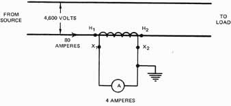
ill. 22-2 A current transformer used with an ammeter
The secondary leads are connected directly to the ammeter. Note that one of the secondary leads is grounded as a safety precaution to eliminate high-voltage hazards.
Caution: The secondary circuit of a transformer should never be opened when there is current in the primary winding. If the secondary circuit's opened when there is current in the primary winding, then the entire primary current is an exciting current which induces a high voltage in the secondary winding. This voltage can be high enough to endanger human life.
Individuals working with current transformers must check that the secondary winding circuit path is closed. At times, it may be necessary to disconnect the secondary instrument circuit when there is current in the primary winding. E.g., the metering circuit may require rewiring or other repairs may be needed. To protect a worker, a small short-circuiting switch is connected into the circuit at the secondary terminals of the cur rent transformer. This switch is closed when the instrument circuit must be disconnected for repairs or rewiring.
Current transformers have very accurate ratios between the primary and secondary current values: the error of most modem current transformers is less than 0.5 percent.
When the primary winding has a large current rating it may consist of a straight conductor passing through the center of a hollow metal core. The secondary winding is wound on the core. This assembly is called a bar-type current transformer. The name is derived from the construction of the primary which actually is a straight copper bus bar. All standard current transformers with ratings of 1,000 amperes or more are bar-type transformers. Some current transformers with lower ratings may also be of the bar type. ill 22-3 shows a bar type current transformer.
ill 22-4 shows a clamp-on ammeter that uses the concept of a window-type cur rent transformer. By opening the clamp and then closing it around the current-carrying conductor, the current in the conductor is measured on the meter.
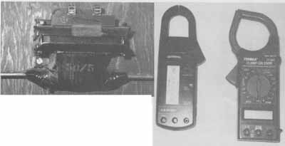
ill. 22-3 Bar type current transformer.
ill. 22-4 Clamp on style ammeters/multimeters.
INSTRUMENT TRANSFORMERS IN A SINGLE-PHASE CIRCUIT
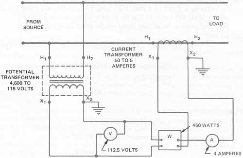
ill. 22-5 Single-phase metering connections
ill 22-5 illustrates an instrument load connected through instrument transformers to a single-phase, high-voltage line. The instruments include a voltmeter ( 22-6), an ammeter, and a wattmeter. The potential transformer is rated at 4,600 to 115 volts; the current transformer is rated at 50 to 5 amperes. The potential coils of the volt meter and the wattmeter are connected in parallel across the low-voltage output of the potential transformer. Therefore, the voltage across the potential coils of each of these instruments is the same. The current coils of the ammeter and the watt meter are connected in series across the secondary output of the current transformer. As a result, the current in the current coils of both instruments is the same. Note that the secondary of each instrument transformer is grounded to provide protection from high-voltage hazards, as provided in Article 250 of the National Electrical Code.
The voltmeter in figure 22-5 reads 112.5 volts, the ammeter reads 4 amperes, and the wattmeter reads 450 watts. To find the primary voltage, primary current, primary power, apparent power in the primary circuit and the power factor, the following procedures are used:
Primary Voltage
Voltmeter multiplier = 4,600/115 = 40
Primary volts = 112.5 x 40
= 4,500 volts
Primary Current
Ammeter multiplier = 50/S = 10
Primary amperes =4 x 10
=40 amperes
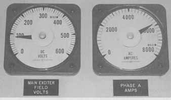
ill. 22-6 Panel mounted meters use transformers to monitor large values
Primary Power
Wattmeter multiplier = Voltmeter multiplier x ammeter multiplier
Wattmeter multiplier = 40 x 10
= 400
Primary watts = 450 x 400
= 180,000 watts or 180 kilowatts
Apparent Power
The apparent power of the primary circuit's found by multiplying the primary volt age and current values.
Apparent power (volt-amperes) = volts x amperes
volt-amperes = 4,500 x 40
= 180,000 watts = 180,000/1,000 = 180 kilowatts
Power Factor
Power factor = Power in Kilowatts/Apparent power in kilovolt-amperes
= 180/180
= 1.00 or 100 percent
INSTRUMENT TRANSFORMERS ON THREE-PHASE SYSTEMS
Three-Phase, Three-Wire System
On a three-phase, three-wire system, two potential transformers of the same rating and two current transformers of the same rating are necessary. It is common practice in three-phase metering to interconnect the secondary circuits. That is, the connections are made so that one wire or device conducts the combined currents of two transformers in different phases.
The low-voltage instrument connections for a three-phase, three-wire system are illustrated in 22-7. Note that the two potential transformers are connected in open delta to the 4,600-volt, three-phase line. This results in three secondary voltage values of 115 volts each. The two current transformers are connected so that the primary of one transformer is in series with line A and the primary winding of the second transformer is in series with line C.
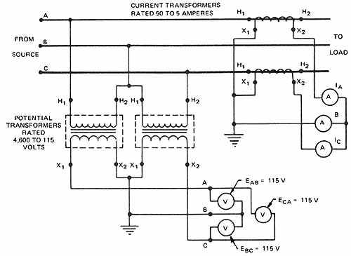
ill. 22-7 Metering connections for three-phase, three-wire system
Note that three ammeters are used in the low-voltage secondary circuit. This wiring system is satisfactory on a three-phase, three-wire system and all three ammeters give accurate readings. Other instruments which can be used in this circuit include a three-phase wattmeter, a three-phase watt-hour meter, and a three-phase power factor meter. When three-phase instruments are connected in the secondary circuits, these instruments must be connected correctly so that the proper phase relationships are maintained. If this precaution isn't observed, the instrument readings will be incorrect. In checking the connections for this three-phase, three-wire metering system, note that the interconnected potential and current secondaries are both grounded to provide protection from high-voltage hazards.
Three-Phase, Four-Wire System
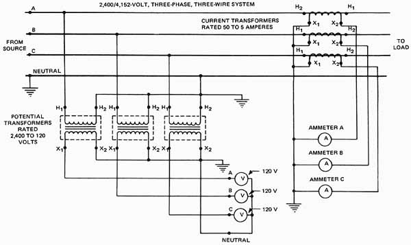
ill. 22-8 Metering connections for three-phase, four-wire system
ill 22-8 illustrates the secondary metering connections for a 2,400/4,152-volt, three-phase, four-wire system. The three potential transformers are connected in wye to give a three-phase output of three secondary voltages of 120 volts to neutral. Three 50-to-5-ampere current transformers are used in the three line conductors. Three ammeters are used in the interconnected secondary circuit. Both the interconnected potential and the current secondaries are grounded to protect against possible high-voltage hazards.
SUMMARY
Instrument transformers are specifically designed to transform voltage and current in very precise ratios. Potential transformers are used to transform high voltages to usable values of 115 or 120 volts for use by standard instruments. Current transformers (CTs) are used to transform large values of ac current down to a 5 amp level so that it can be used by standard instruments. DC current levels are typically reduced to a usable level through the use of shunts. The shunt has a primary-load current rating and the meter is then connected across the shunt. The meter is designed to operate at 50 millivolts.
QUIZ
1. What are the two types of instrument transformers?
a.
b.
2. Why must the secondary circuit of a current transformer be closed when there is current in the primary circuit? __________
3. A transformer is rated at 4,600/115 volts. A voltmeter connected across the secondary reads 112 volts. What is the primary voltage?
4. A current transformer is rated at 150/5 amperes. An ammeter in the secondary circuit reads 3.5 amperes. What is the primary current? _______
5. A 2,300/115-volt potential transformer and a 100/5-ampere current transformer are connected on a single-phase line. A voltmeter, an ammeter, and a wattmeter are connected in the secondaries of the instrument transformers. The voltmeter reads 110 volts, the ammeter reads 4 amperes, and the wattmeter reads 352 watts. Draw the connections for this circuit. Mark leads H X and so forth. Show all voltage, current, and wattage readings.
6. Complete a circuit using instrument transformers to measure voltage and amperage. Include termninal markings.
FROM SOURCE TO LOAD
7. What is the primary voltage of the single-phase circuit given in question 5?
8. What is the primary current in amperes of the single-phase circuit given in question 5?
9. What is the primary power in watts in the single-phase circuit given in question 5?
10. What is the power factor of the single-phase circuit given in question 5?
Select the correct answer for each of the following statements.
11. The secondary for a potential transformer is usually wound for
a. 10 volts. c. 230 volts.
b. 115 volts. d. 500 volts.
12. Potential transformer secondaries are grounded to
a. stabilize meter readings.
b. insure readings with an accuracy of 0.5 percent.
c. complete a system with the primaries.
d. eliminate high-voltage hazards.
13. A transformer used to reduce current values to a size where small meters can register them is a(n)
a. autotransformer. c. potential transformer.
b. distribution transformer. d. current transformer.
14. The primary of a large current transformer may consist of
a. many turns of fine wire.
b. few turns of fine wire.
c. many turns of heavy wire.
d. straight-through conductor.
15. The standard ampere rating of the secondary of a current transformer is
a. 5 amperes. c. 15 amperes.
b. 50 amperes. d. 15 amperes.
16. The secondary circuit of a current transformer should never be opened when current is present in the primary because
a. the meter will burn out.
b. the meter won't operate.
c. dangerous high voltage may develop.
d. primary values may be read on the meter.