AMAZON multi-meters discounts AMAZON oscilloscope discounts
OBJECTIVES:
• explain how and why transformers are used for the transmission and distribution of electrical energy.
• describe the basic construction of a transformer.
• distinguish between the primary and secondary windings of a transformer.
• list, in order of sequence, the various steps in the operation of a step-up transformer.
• make use of appropriate information to calculate the voltage ratio, voltages, cur rents, and efficiency for step-up and step-down transformers.
• explain how the primary load changes with the secondary load.
It is neither efficient nor economically feasible to generate large quantities of direct-current electrical energy. The invention of the transformer was a milestone in the progress of the electrical industry. The transformer increases or decreases the voltage of large quantities of alternating-current energy efficiently, safely, and conveniently. A large power distribution station is shown in ill. 1.
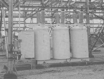
ill. 1: Substation with three individual oil filled circuit breakers.
Large amounts of alternating current energy may be generated at a convenient volt age, using steam, nuclear, or water power. Transformers are used first to increase this energy to a high voltage for transmission over many miles of transmission wires, and then to decrease this voltage to values which are convenient and safe for use by the consumer.
ELEMENTS OF TRANSFORMERS
A transformer consists of two or more conductor windings placed on the same iron core magnetic path, as shown in ill. 2.
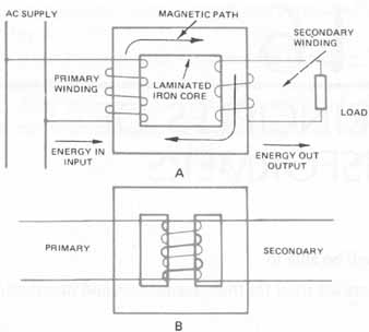
ill. 2: Parts of a transformer
Laminated Core
The iron core of a transformer is made up of sheets of rolled iron. This iron is treated so that it has a high magnetic conducting quality (high permeability) throughout the length of the core. Permeability is the term used to express the ease with which a material will conduct magnetic lines of force. The iron also has a high ohmic resistance across the plates (through the thickness of the core). It is necessary to laminate the iron sheets (ill. 3) to reduce hysteresis and eddy currents which cause heating of the core.
Windings
A transformer has two windings: the primary winding and the secondary winding. The primary winding is the coil which receives the energy. It is formed, wound and fitted over the iron core. The secondary, winding is the coil which provides the energy at a transformed or changed voltage—increased or decreased.
Transformers by definition are used to transfer energy from one ac system to another by electromagnetic means. They don't change the amount of power significantly; only minor wattage losses occur in the transformer. If the transformer increases the voltage, it's called a step-up transformer. If it decreases the voltage, it's called a step-down transformer.
The secondary voltage is dependent upon:
• the voltage of the primary,
• the number of turns on the primary winding, and
• the number of turns on the secondary winding.
Certain types of core-type transformers have the primary and secondary wire coils wound on separate legs of the core, (See ill. 2A). The primary and secondary wire coils can also be wound on top of one another, as shown in ill. 2B.Winding in this manner improves transformer efficiency and conserves energy. When stating the transformer ratio, the primary is the first factor of the ratio. This tells which winding, high or low, is connected to the power source.
CONSTRUCTION OF TRANSFORMERS
Three major types of construction for transformer cores are: core type, shell type, and cross or H type (ill. 4).
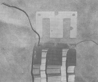
ill. 3 “E” laminations used in transformer core construction
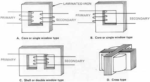
ill. 4 Major construction types for transformer cores: A. Core
or single window type; B. Core or single window type; C. Shell or double
window type; D. Cross type
Core Type
In a core-type transformer, the primary winding is on one leg of the transformer and the secondary winding is on the other leg. A more efficient type of core construction is the shell type in which the core is surrounded by a shell of iron (ill. 4A and B).
Shell Type
The shell-type or double window-type core transformer (ill. 4C), is probably used most frequently in electrical work. In terms of energy conservation, this transformer design operates at 98 percent or higher efficiency.
Cross or H Type
The cross or H type of core is also called the modified shell type. The coils are surrounded by four core legs. The cross type is really a combination of two shell cores set at right angles to each other. The windings are located over the center core which is four times the area of each of the outside legs. This type of core is very compact and can be cooled easily. It is used for large power transformers where voltage drop and cost must be kept to a minimum. These units are usually immersed in oil for high insulation properties and effective cooling. Another method of cooling the transformers is by forced air. Transformers should never be immersed in water for cooling. Accidental flooding, such as in underground transformer vaults, should be pumped (ill. 4D).
ELEMENTARY PRINCIPLES OF TRANSFORMER OPERATION
According to Lenz’s Law, a voltage is induced in a coil whenever the coil current is increased or decreased. This induced voltage is always in such a direction as to oppose the force producing it. Called induction, this action is illustrated by arranging two loops of wire, as shown in ill. 5.
Note in ill. 5 the progressive enlargement of the magnetic field about one side of each loop as the current builds up. The strength of the magnetic field increases as the electrical current through the conductor increases from the power source. ill. 5 also shows the field pattern during the period that the current decreases.
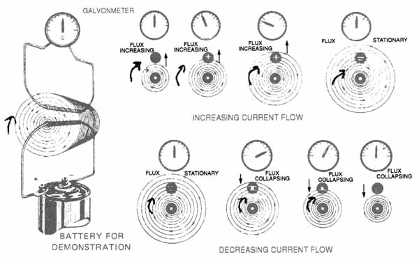
ill. 5 Magnetic induction (Electron flow): INCREASING CURRENT FLOW;
FLUX INCREASING; FLUX COLLAPSING; BATTERY FOR DEMONSTRATION ; DECREASING
CURRENT FLOW;
ill. 5 uses the left-hand rule for conductors. Grasp the conductor with your left hand with your thumb extended in the direction of the electron flow. Your fingers will indicate the direction of the magnetic flux. The flux expand outward from the conductor as the current flow increases and contracts toward the conductor center as the current flow diminishes.
As the current builds up to its maximum value, the circular magnetic lines around the wire move outward from the wire. This outward movement of magnetic lines of force cuts across the conductor of the second loop. As a result, an emf is induced and current circulates in the loop, as indicated on the galvanometer located above the conductor.
When the current reaches its steady state in the first circuit, the flux is stationary and no voltage is induced in the circuit. The galvanometer indicates zero current.
When the battery circuit's opened, current falls to zero and the flux collapses. The collapsing flux cuts through the second circuit and again induces an emf. The second induced current has a direction opposite to that of the first induced current, as indicated by the galvanometer needle. The final stage shows a steady state with no field and no induced cur rent. This action is automatic with ac applied.
The loops of wire may be replaced by two concentric coils (loops with many turns) to form a transformer. ill. 6 shows a transformer which has a primary winding, an iron core and secondary winding. When a changing or alternating current is delivered to the primary winding, the changing primary current produces a changing magnetic field in the iron core. This changing field cuts through the secondary coil and thus induces a voltage, the value depends on the number of conductors in the secondary coil cut by the magnetic lines. This is called mutual inductance. Commercial transformers generally have fixed cores which provide complete magnetic circuits for efficient operation where there is little flux leakage and high mutual induction.
VOLTAGE RATIO
According to Lenz’s law, one volt is induced when 100,000,000 magnetic lines of force are cut in one second. The primary winding of a transformer supplies the magnetic field for the core. The secondary winding, when placed directly over the same core, sup plies the load with an induced voltage which is proportional to the number of conductors cut by the primary flux of the core.
The shell-type transformer shown in ill. 6 is designed to reduce the voltage of the power supply.
In ill. 6:
Np = number of turns in the primary winding
Np = number of turns in the secondary winding
Ip = current in the primary winding
Is = current in the secondary winding
Assume that Np = 100 turns
Ns = 50 turns
E (supply) = 100 volts, 60 hertz
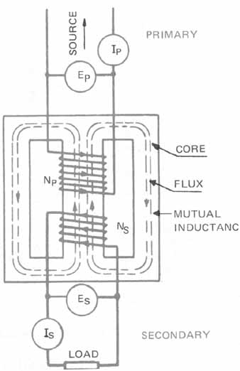
ill. 6 Single-phase transformer showing mutual inductance of two
coils
The alternating supply voltage (100U), produces a current in the primary which magnetizes the core with an alternating flux. (According to Lenz’s Law, a counter emf is induced in the primary winding. This counter emf is called self-inductance and opposes the impressed voltage). Since the secondary winding is on the same core as the primary winding, only 50 volts is induced in the secondary because only half as many conductors are cut by the magnetic field.
At no-load conditions, the following ratio is true:
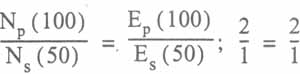
Therefore, the ratio of 2 to 1 indicates that the transformer is a step-down transformer which will reduce the voltage of the power supply. Transformers either step up or step down the supply voltage.
Refer to ill. 7 for the following example. The primary winding of a transformer has 100 turns, and the secondary has 400 turns. An emf of 110 volts is applied to the primary. What is the voltage at the secondary and what is the ratio of the transformer?
This transformer has a 440/110 = 4/1 step-up ratio, or 1:4
CURRENT RATIO
Current ratio in a transformer is the inverse of the ratio for voltage transformation. The transformer does not create power and it's not designed to consume power. The input power should be very close to the output power. Therefore, if the volt-amps input equals the volt-amps output and the voltage level is increased, the current level is decreased. The voltage ratio and the current ratio are inversely proportional.
If the load current of the transformer illustrated in 7 is 12 amperes, the primary current must be such that the product of the number of turns and the value of the current (ampere-turns primary) equal the value of the ampere-turns secondary.
Check of Solution for Current
Np x Ip = Ns x Is; 100 x 48 = 400 x 12; 4,800 = 4,800
The current ratio is an inverse ratio; that's , the greater the number of turns, the less the current for a given load. Practical estimates of primary or secondary currents are made by assuming that transformers are 100 percent efficient.
E.g., assume that
Watts input = Watts output
or
Primary watts = Secondary watts
Therefore, for a 1,000-watt, 100/200-volt step-up transformer:
Is = 1,000W / 200 V = 5 amperes
Ip = 1,000W / 100V = 10 amperes
The greater the current the larger size the wire leads are on the transformer. From this information we can determine the high and low voltage sides.
Higher voltage = lower current therefore smaller wire size
Lower voltage = higher current therefore larger size wire
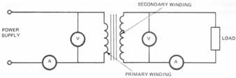
ill. 8 Schematic diagram of a step-up transformer
Example: A machine tool being relocated has a control transformer disconnected. The nameplate is illegible due to corrosion. The motor power circuit's 480 volts. The motor controller operates on 120 volts control. Which is the primary and secondary of the control transformer? The higher voltage has the smaller wire size. Therefore, this is to be connected to the 480 volts.
The use of an ohmmeter can also tell us which winding has the greater resistance. By measuring each winding, we find that the greater the resistance, the greater is the voltage connection because it has more turns of smaller wire. Remember, the term “primary” refers to the supply side of the transformer. The term “secondary” refers to the load side (ill. 8).
SCHEMATIC DIAGRAM OR SYMBOL
A step-up transformer is usually shown in schematic form, as illustrated in ill. 8. The ratio of turns, primary to secondary, isn't pictorially shown. This is usually shown as a step-up or step-down symbol representation.
PRIMARY LOADING WITH SECONDARY LOADING
The current in the secondary controls the current in the primary. When the secondary circuit's complete by placing a load across it, the secondary emf causes a current to flow. This builds up a magnetic field in opposition to the primary field. This opposing, or demagnetizing, action reduces the effective field of the primary flux, which in turn reduces the primary cemf, thereby permitting more current to flow in the primary. The greater the current flow in the secondary, the greater is the field produced by the secondary. This results in a reduced primary field; hence, a reduced primary cemf is produced. This condition permits greater current flow in the primary. This entire process will repeat itself whenever there is any change in the value of the current in either the primary or the secondary. A transformer adjusts itself readily to any normal change in secondary load. However, if a direct short is placed across the secondary, the abnormally great amount of current flowing causes the primary current to rise in a like manner, resulting in damage to, or complete burn-out of, the transformer, if it's not protected properly.
EFFICIENCY
The efficiency of all machinery is the ratio of the output to the input.
Efficiency = output / input
In general, transformer efficiency is about 97 percent. Only three percent of the total voltage at the secondary winding is lost through the transformation. The loss in voltage is due to core losses and copper losses.
The core loss is the result of hysteresis (magnetic friction) and eddy currents (induced currents) in the iron core.
The copper loss is power lost in the copper wire of the windings. Therefore, taking these losses into consideration,
% Efficiency = Watts output (secondary) / Watts input (primary) X 100
where: Watts input = Watts output + losses
SUMMARY
Transformers are very useful in delivering the exact voltage needed to a customers site. DC cannot be easily changed from one voltage level to another. There are no true dc transformers. AC can be increased or decreased easily through the electromagnetic coupling of the transformer coils. Transformers can be used to: (1) step up the voltage; (2) step down the voltage; or (3) simply isolate the transformer primary system from the transformer secondary system.
QUIZ
A. Select the correct answer for each of the following statements.
1. When the primary winding has more turns than the secondary, the voltage in the secondary winding is _______
a. increased. c. decreased.
b. doubled. d. halved.
2. In the coils of a transformer, the motion of the flux is caused by the
a. direct current. c. moving secondary.
b. rotating primary. d. alternating current.
3. Energy is transferred from the primary to the secondary coils without a change in:
a. frequency. c. current.
b. voltage. d. ampere-turns.
4. Transformer efficiency averages
a. 79 percent. c. 50 percent.
b. 97 percent. d. 100 percent.
5. A transformer has a primary coil rated at 150 volts and a secondary winding rated at 300 volts. The primary winding has 500 turns. How many turns does the secondary winding have?
a. 250 c. 1,000
b. 2,500 d. 10,000
6. A control transformer is a step-down-type transformer. Com pared to the secondary winding the primary winding is
a. larger in wire size.
b. smaller in wire size.
c. the same size as the secondary.
d. connected to the load.
7. The current in the secondary winding
a. is higher than the current in the primary.
b. is lower than the current in the primary.
c. controls the current in the secondary.
d. controls the current in the primary.
B. Solve the following problems:
8. A 110/220-volt Step-up transformer has 100 primary turns. How many turns does the secondary winding have?
9, A transformer has 100 primary turns and 50 secondary turns. The current in the secondary winding is 20 amperes. What is the current in the primary winding.
10. What is the ratio of a transformer that has a secondary voltage of 120 volts when connected to a 2,400-volt supply?
11. A 7,200/240-volt step-down transformer has 1,950 primary turns. Determine the number of turns in the secondary winding.
12. A 2,400/240-volt step-down transformer has a current of 9 amperes in its primary and 85 amperes in its secondary. Determine the efficiency of the transformer.