AMAZON multi-meters discounts AMAZON oscilloscope discounts
OBJECTIVES
• diagram the connection of three single-phase transformers to form a delta-wye transformer bank.
• describe how a delta-wye transformer bank is used to step down voltages.
• describe how a delta-wye transformer bank is used to step up voltages.
• diagram the connection of three single-phase transformers to form a wye-delta transformer bank.
• describe how a wye-delta transformer bank is used to step down voltages.
• list advantages and disadvantages of a single three-phase transformer as compared to three single-phase transformers.
Five commonly-used methods of connecting single-phase transformers to form three-phase transformer banks are: delta-delta, open delta, wye-wye, delta-wye, and wye-delta connections. The delta-delta, open delta, and wye-wye connections are described in previous units.
This unit covers the delta-wye and wye-delta connections. The current and voltage relationships for each of these methods of three-phase transformation are explained, and examples of several applications for each connection method are shown.
STEP-DOWN APPLICATION FOR DELTA-WYE TRANSFORMER BANK
Assume that electrical energy must be transformed from a 2,400-volt, three-phase, three-wire input to a 120/208-volt, three-phase, four-wire output. Each of the three single-phase transformers is rated at 20 kVA, with 2,400 volts on the high-voltage windings and 120 or 240 volts on the low-voltage windings.
[176-177]
…windings are connected in delta to the generating station bus bars; therefore, each primary coil winding has 13,800 volts applied to it. The transformers have a step up ratio of 1 to 5. As a result, the voltage output of the secondary of each single-phase transformer is 5 x 13,800
or
69,000 volts.
ill 2 shows that the three secondary windings are connected in wye. Each high-voltage secondary winding is connected between the secondary neutral and one of the three line leads. The voltage between the neutral and any one of the three line leads is the same as the secondary coil voltage or 69,000 volts. The voltage across the three line leads is 1.73 x 69,000 = 119,370 volts. The grounded neutral wire on the high-voltage secondary output must be used to obtain balanced three-phase voltages even though the load current may be unbalanced. Not only is this neutral wire grounded at the transformer bank, it's also grounded at periodic intervals on the transmission line. As a result, it protects the three high-voltage secondary windings of the single-phase transformers from possible damage due to lightning surges.
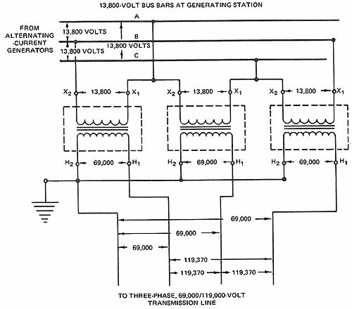
ill. 2 Delta-wye transformer bank
WYE-DELTA TRANSFORMER BANK
A transformer bank connected in wye-delta is the type most often used to step down relatively high transmission line voltages (60,900 volts or more) at the consumer’s location. Two reasons for selecting this type of transformer bank are that the three-phase volt age is decreased by the transformer ratio multiplied by the factor 1.73, and the insulation requirements for the high-voltage primary windings are reduced.
As an example, assume that it's necessary to step down a three-phase 60,900 volt input to a three-phase, 4,400-volt output ( 3). The primary windings are connected in wye to a three-phase, four-wire transmission line. The three line voltages are 60,900 volts between phase conductors each and the voltage from each line wire to the grounded neutral is 35,200 volts.
Each of the three single-phase transformers is rated at 1,000 kVA, with 35,200 volts on the high-voltage side and 4,400 volts on the low-voltage side. The voltage ratio of each transformer is 8 to 1.
ill 3 shows that the secondary windings are connected in delta, resulting in a line voltage of 4,400 volts on the three-phase, three-wire secondary system feeding to the load.
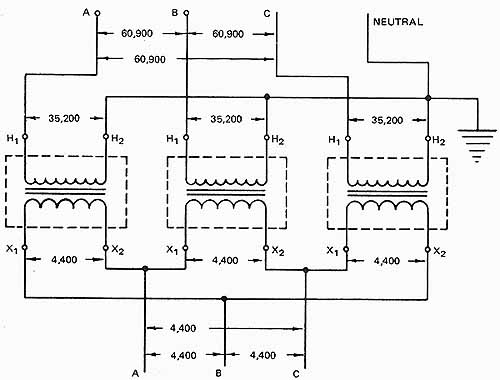
ill. 3 Wye-delta transformer bank
The total kVA capacity of a wye-delta transformer bank is determined by adding the kVA rating of each single-phase transformer in the bank. For the bank in figure 3, the total kVA capacity is equal to 1,000 + 1,000 + 1,000=- 3,000 kVA.
THREE-PHASE TRANSFORMERS
Voltages on three-phase systems may be transformed using three-phase transformers. The core of a three-phase transformer is made with three legs. A primary and a secondary winding of one phase are placed on each of the three legs. These transformers may be connected in delta-delta, wye-wye, delta-wye or wye-delta. The connections are made inside the transformer case. For delta-delta connections, three high-voltage and three low-voltage leads are brought out. Four leads are brought out when any wye-connected windings are used. This fourth lead is necessary for the neutral wire connection.
The three-phase transformer occupies less space than three single-phase transformers because the windings can be placed on one core in the three-phase transformer case, ( 5). The efficiency of a three-phase transformer is higher than the overall efficiency of three single-phase transformers connected in a three-phase bank.
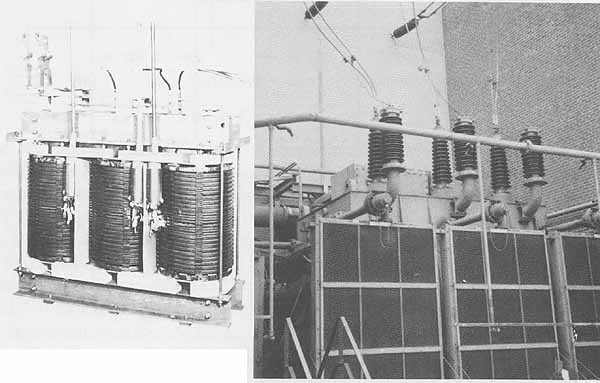
ill. 4 A three-phase transformer (Assembled core and coils for a
500-kVA, 60-Hz, 13,800 to 2,400-V transformer) ; ill. 5 34 KV power transformer at a generating station
However, there is one disadvantage to the use of a three-phase transformer. If one of the phase windings becomes defective, the entire three-phase unit must be taken out of service. If a single-phase transformer in a three-phase bank becomes defective it can be replaced quickly. The resultant power interruption is brief. For this reason, many transformer installations consist of banks of three single-phase transformers. ill 5 shows a three-phase single unit transformer in operation.
SUMMARY
Transformers need not be connected in the same pattern on the primary and the secondary. Depending on the desired voltage level and level of step-up (increase) or step-down (decrease), the patterns may change. The two most popular patterns are the wye and delta. To get the greatest step-up, the transformation ratio is best if the primary is connected delta and the secondary is connected wye. Likewise, to get the largest decrease in voltage, the ratio of transformation is the greatest if the primary is connected wye and the secondary is connected delta. Remember that the current ratios are the inverse of the voltage ratios.
QUIZ
1. Diagram the connections for three single-phase transformers connected in delta-wye to step down 2,400 volts, three phase, three wire, to a 120/208-volt, three-phase, four-wire service. Three single-phase transformers are to be used. Each transformer is rated at 25 kVA, with 2,400 volts on the high-voltage side and 120 volts on the low-voltage side. Mark leads H X and so forth. Show all voltages.
2. What is the total kVA capacity of the delta-wye transformer bank in question 1?
3. What are two applications of a three-phase, delta-wye transformer bank?
a.
b.
4. What is one practical application of a three-phase, wye-delta transformer bank?
[182-184]