AMAZON multi-meters discounts AMAZON oscilloscope discounts
OBJECTIVES
• diagram the simple wye connection of three transformers.
• list the steps in the procedure for the proper connection and checking of the primary and secondary windings of three single-phase transformers connected in a wye arrangement.
• state the voltage and current relationships for wye-connected, single-phase transformers.
• describe how the grounded neutral of a three-phase, four-wire, wye-connected transformer bank maintains a balanced voltage across the windings.
• state how the kVA capacity of a wye-wye-connected transformer bank is obtained.
Voltage transformation on three-phase systems can also be accomplished using wye-connected single-phase transformers. To avoid errors when wye connecting single-phase transformers, a systematic method of making the connections should be used. The electrician should know the basic voltage and current relation ships common to this type of connection.
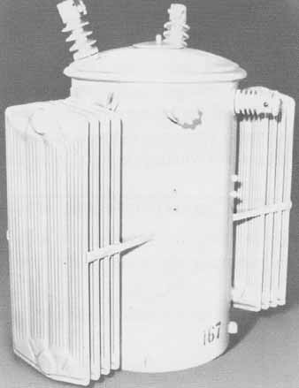
ill. 1: Single-phase, round coil transformer (McGraw-Edison
Company, Power Systems Division)
FUNDAMENTAL WYE CONNECTION
A simple wye system is formed by arranging three single-phase coils so that one end of each coil is connected at a common point ( 2). Note that when these connections are shown in a schematic diagram, they resemble the letter Y (written wye). This configuration is also known as a “star” connection.
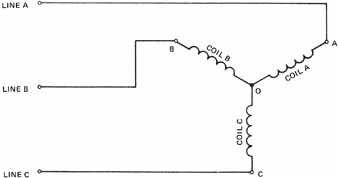
ill. 2: Simple wye connection
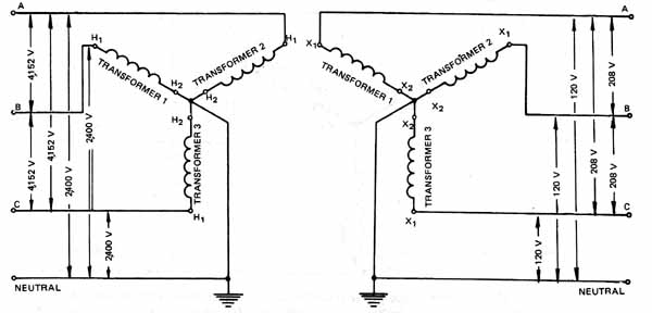
As an example, figure 3 shows the wye-wye connection of three single-phase transformers to step down a three-phase input of 4,152 volts to a three-phase output of 208 volts: Each transformer must be voltage rated for its applications. The H leads or primary winding ends of the transformer are connected together. The beginning or H lead of each transformer is connected to one of the three line leads.
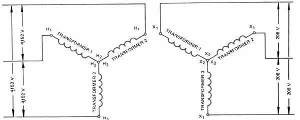
ill. 3 Elementary diagram of wye-wye-connected transformer bank
Two of the primary windings are connected across each pair of line wires. Each transformer primary winding is rated at 2,400 volts and the actual voltage applied to each of these three windings is 2,400 volts. Note that the potential across each pair of line leads is 4,152 volts and not the 2,400 + 2,400 = 4,800 volts which might be expected because of the connection of two coils.
The value of 4,152 volts arises from the fact that the voltage applied to each of the primary windings is out of phase with the voltages applied to the other primary windings. As a result, these winding voltages cannot be added directly to obtain the line voltage. Rather, the line voltage is equal to 1.73 x coil voltage. Therefore, for the input side of the transformer bank in figure 3 where the voltage on the primary winding of each transformer is 2,400 volts, the line voltage is
Line voltage = 1.73 x coil voltage
= 1.73 x 2,400
= 4,152 volts
If the coil voltage must be checked and the line voltage is known, the same value of 1.73 can be used. For this situation, the coil voltage is obtained by dividing the line volt age by 1.73.
Coil voltage = line voltage/1.73
= 4,152/1.73
= 2,400 volts
Thus, wye-connected transformer banks have only 58 percent (1/1.73 = 0.58) of the line voltage applied to each of the three transformer windings. After the high-voltage primary connections are completed, the three-phase, 4,152-volt input may be energized. It isn't necessary to make any polarity tests on the input (primary) side.
POLARITY TEST FOR UNMARKED AND NEW TRANSFORMERS
The next step is to connect the low-voltage output (secondary) windings in wye ( 3). The following procedure must be followed when making the secondary connections.
1. Check to see that the voltage output of each of the three transformers is 120 volts. (for this example)
Caution: De-energize all circuits before making connections.
2. Connect the X ends of two low-voltage secondary windings.
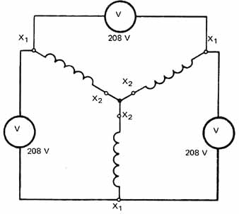
ill 4 illustrates two secondary coils with the X2 coil ends connected. The voltage across the open ends should be 1.73 x 120 = 208 volts. However, if the leads on one transformer are reversed, the voltage across the open ends will be 120 volts.
ill. 4 Two transformers correctly connected
ill 5 illustrates two transformers connected incorrectly. The voltage across the open ends is only 120 volts. If the leads of transformer 2 are reversed, the connections will be correct and the voltage across the open ends will be 208 volts.
ill. 5 (above right) Two transformers incorrectly connected
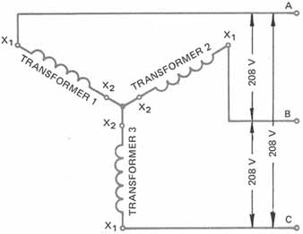
3. Connect the X lead of the low-voltage secondary winding of transformer 3 with the X leads of the other two transformers.
The proper wye connection of the low-voltage secondary windings of the three single-phase transformers is illustrated in 6. The voltage across each pair of open ends should be 1,73 x 120 = 208 volts. If the voltage across the open ends is correct, then the line leads feeding to the three-phase, 208-volt secondary system may be connected.
ill. 6: Three single-phase transformers properly connected in a wye
arrangement
ill. 7: Three single-phase transformers properly connected to the
line
ill 7 illustrates the secondary windings connected in wye with the line leads properly connected. Since each of the line wires is connected in series with one of the transformer windings, the current in each winding is equal to its respective line current.
Whenever single-phase transformers are connected in wye, the following current and voltage relationships are true.
1. The line voltage is equal to 1.73 x winding voltage.
2. The line current and the winding current are equal.
The wye-wye connection scheme is satisfactory as long as the load on the secondary side is balanced. E.g., this type of connection can be used if the load consists only of a three-phase motor load where the load currents are balanced. The wye-wye connection is unsatisfactory where the secondary load becomes greatly unbalanced. An unbalanced load results in a serious unbalance in the three output voltages of the transformer bank.
THREE-PHASE, FOUR-WIRE WYE CONNECTION
Voltage unbalancing in the secondary of the transformer bank can be nearly eliminated if a fourth wire (neutral wire) is used. This neutral wire connects between the source and the neutral point on the primary side of the transformer bank.
In the connection diagram ( 8) a three phase, four-wire system is used to feed the three-phase, high-voltage input to the transformer bank. The grounded neutral wire is connected to the common point where all three high-voltage primary winding ends or H leads connect. The voltage from the neutral to any one of the three line wires is 2,400 volts. Each high-voltage winding is connected between the neutral and one of the three line loads. Therefore, 2,400 volts is applied to each of the three high-voltage primary windings. The voltage across the three line leads is 1.73 x 2,400 volts or 4,152 volts.
ill. 8.
The neutral wire maintains a relatively constant voltage across each of the high-voltage primary windings even though the load is unbalanced. Because the neutral wire is grounded, it helps protect the three high-voltage primary windings from lightning surges.
A three-phase, four-wire system also feeds from the low-voltage secondary side of the transformer bank to the load. Each low-voltage secondary winding is connected between the secondary grounded neutral and one of the three line leads. As on the primary side, the grounded neutral helps protect the low-voltage secondary windings from lightning surges.
The voltage output of each secondary winding is 120 volts. The voltage between the neutral and any one of the three line leads on the secondary side is 120 volts, as illustrated in 8. The voltage across the three line leads is 1.73 x 120 = 208 volts. Thus, by using a three-phase, four-wire secondary, two voltages are available for different types of loads: 208 volts, three phase, for industrial power loads such as three-phase motors, and 120 volts, single phase, for lighting loads.
Many single-phase transformers are designed so that the low-voltage side consists of two 1volt windings. These two windings can be connected in series for 240 volts or in parallel for 120 volts.
ill 9 shows three single-phase transformers connected as a wye-wye bank. Each transformer has two 1volt, low-voltage windings. For each single-phase transformer, the low-voltage coils are connected in parallel to give a voltage output of 120 volts. Note in figure 9 that the secondary output windings of the three transformers are connected in wye. This three-phase, four-wire secondary system provides two different types of service:
- three-phase, 208-volt service for motor loads ill. 8 Wye-wye transformer bank with neutral connection
- single-phase, 1volt service for lighting loads
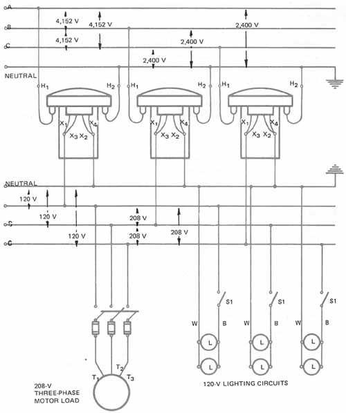
ill. 9 Wye-wye transformer bank connections
The 120/208-volt wye system is commonly used in schools, stores, and offices. Another popular system for large installations is the 480/277-volt wye system. Some applications of this system include:
• motors connected to 480 volts (phase to phase);
• fluorescent lighting fixtures connected to 277 volts (phase to neutral);
• 115 volt outlets, incandescent lamps, and appliances connected to 1volt circuits supplied from single-phase, 480//120/240-volt transformers or three-phase, 480//208Y/1volt transformers. These separate transformers are connected to the 480-volt feeders for the primary source.
Three single-phase transformers of the same kilovolt-ampere capacity are used in most wye-wye-connected transformer banks. The total kilovolt-ampere capacity of a wye-wye-connected bank is found by adding the individual kVA ratings of the transformer. If each transformer is rated at 25 kVA, then the total kVA is 25 + 25 + 25 = 75 kVA.
If one transformer becomes defective, it must be replaced before the transformer bank can be reenergized. A wye-wye-connected transformer bank cannot be reconnected in an emergency situation using only two single-phase transformers, such as in the open-delta system.
SUMMARY
Single-phase transformers can be connected in a wye or star pattern to achieve the desired three-phase and single-phase voltages required by many commercial customers. By connecting the single phases in a wye pattern, the line voltages can be increased by a factor of 1.73 times the coil voltage. This increased level of voltage is often desirable to reduce the line current drawn by a load. By increasing the voltage, the current will be less for a specific watt load. Be sure to check all transformer polarities and check the final connections for a solid ground if using the three-phase, four-wire wye-connected system.
QUIZ
1. Draw a connection diagram for three wye-wye-connected single-phase transformers. This transformer bank is used to step down 2,400/4,152 volts on a three-phase, four-wire primary to 120/208 volts on a three-phase, four-wire secondary. Each transformer is rated at 20 kVA, with 2,400 volts on the high-voltage winding and 120 volts on the low-voltage winding. Mark leads H X and so forth; show all voltages.
2. What is the total kVA capacity of the wye-wye transformer bank in question 1?
3. A grounded neutral wire is used with a wye-wye-connected transformer bank for what purpose?
4. The three-phase, four-wire secondary output of a wye-connected transformer bank can be used for what two types of load?
a.
b.
5. List the steps that may be used in connecting three single-phase transformers in wye.
a.
b.
c.
6. When single-phase transformers are connected in a three-phase Y,
a. what is the line current compared with the phase-winding current?
b. what is the line voltage compared with the phase-winding voltage?