AMAZON multi-meters discounts AMAZON oscilloscope discounts
OBJECTIVES:
• identify three-phase transformers.
• determine the lead identification of three-phase transformers.
• explain the efficiencies involved.
• determine the benefits and the detriments of three-phase transformers.
Three-phase transformer units are designed to be installed as a complete unit. Instead of installing three individual transformers and field-connecting them into the desired pattern, a transformer (pre-assembled as a unit) is used. The transformer windings are assembled on a common core and the appropriate leads are brought out. There are usually three high-voltage leads marked H1-H2-H3. The secondary leads would be marked X1-X2-X3. In three-phase transformers the phase rotation or phase sequence, is critical between the primary and the secondary.
Each of the phase windings within the transformer normally have the same relative polarity. This means that if the transformer connection is a subtractive polarity, then the other phase connections would also be subtractive. However, the three-phase polarity depends on how the leads are brought out to the secondary terminals. Terminal markings alone don't indicate all the relationships between primary and secondary. Three-phase transformers should have a voltage vector diagram to show the angular-phase displacement between the primary and the secondary and also the phase-sequence order. ill 1 shows a voltage vector diagram for a three-phase transformer connected delta-to-delta. ANSI (American National Standards Institute) defines the angular displacement as the angle between H1—N and X1 — N where N is the neutral point in the vector diagram. In fgr 1 the displacement is zero degrees. This means that the relationship of primary phase sequence is H1, H2, H3 and the secondary phase rotation is X1, X2, X3. The same delta-to-delta configuration of a three-phase transformer may have an angular displacement of 180 degrees. In this case the vector diagram would appear as illustrated in 2. The difference is in the internal connection of the secondary coils. These changes in secondary connections can be seen in the coil connection diagrams.
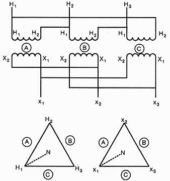
ill. 1 Internal connections determine zero degree angular displacement
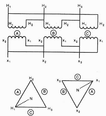
ill. 2 Internal connections to secondary winding determine 180 degree
angular displacement
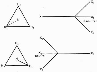 ill. 3 Delta -Y transformers are in group three transformers with
30 degree angular displacement
ill. 3 Delta -Y transformers are in group three transformers with
30 degree angular displacement
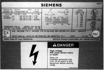 ill. 4 Transformer nameplate
Most three-phase dry-type distribution transformers are connected as a primary delta-connection. The secondary can be connected as a wye or a delta, and the leads brought out to the connection terminals. If the pattern is a delta-to-delta pattern, the displacement may be zero degrees or 180 degrees. If the secondary pattern is a wye, the angular displacement is typically 30 degrees. ill 3 illustrates what a delta-wye pattern may look like. ill 4 shows a three-phase transformer nameplate with the voltage vector diagrams and also the tap connection pattern for connecting primary volt ages from 580 volts to 433 volts to obtain 208 volt, 3-phase output.
PARALLELING THREE-PHASE TRANSFORMERS
Knowing the voltage vectors will allow you to properly parallel three-phase transformers for increased load capacity. It is only necessary to connect the similarly marked high- and low-voltage terminals if the transformers have the same voltage ratio, the same percent impedance, and the same angular displacement.
If the transformers are delta-wye or wye-to-delta, the angular displacement is 30 degrees. When paralleling three-phase transformer units, only transformers with the same displacement should be connected. The only way to change the angular displacement is to reconnect the internal lead of the individual coils.
Advantages and Disadvantages
Because three-phase transformers are wound on the same core, the efficiency of transformation is higher, with less flux leakage. Typically the cost is less for a three-phase unit compared to the same capacity system using three single-phase units. The disadvantage of a single-unit housing a poly-phase transformer is that if one coil fails, the entire transformer must be replaced, rather than just one transformer phase.
SUMMARY
Three-phase transformers are easier to install in transformer installations because all the internal connections are done. The same NEC regulations apply for three single-phase or for one poly-phase transformer installation. Care must be taken when connecting multiple three-phase transformer to supply a load. The connection pattern and the phase displacement must be considered. Three-phase transformers are more efficient in the transformation of power because of the common core and winding system. The disadvantage of the three-phase unit transformer is that if one phase fails, the whole transformer must be replaced.
QUIZ
1. In three-phase transformers, what is meant by zero degrees angular displacement?
2. List some of the conditions to be observed in paralleling three-phase transformers.
3. What are some of the advantages of three-phase transformers, compared to three single-phase transformers?_______________________
4. What could be a disadvantage to connecting a three-phase transformer instead of three single-phase transformers? __________________
5. How does the NEC distinguish between three single-phase transformers and a single three-phase transformer? __________________
6. Name two possible patterns that can be connected when using three-phase transformers.