AMAZON multi-meters discounts AMAZON oscilloscope discounts
Electronic systems and controls have gained wide acceptance in the motor control industry; consequently it has become essential to be familiar with power electronic devices. This section presents a broad overview of diodes, transistors, thyristors, and integrated circuits (ICs) along with their application in motor control circuits.
GOALS:
- 1. Understand the operation and applications of different types of diodes. [below]
- 2. Understand the operation and applications of different types of transistors.
- 3. Understand the operation and applications of different types of thyristors.
- 4. Understand the operation and circuit function of different types of integrated circuits.
Semiconductor Diodes
Diode Operation
The PN-junction diode, shown in Ill. 1, is the most basic of semiconductor devices.
This diode is formed by a doping process, which creates P-type and N-type semiconductor materials on the same component. An N-type semiconductor material has electrons (represented as negative charges) as the current carriers while the P-type has holes (represented as positive charges) as the current carriers. N-type and P-type materials exchange charges at the junction of the two materials, creating a thin depletion region that acts as an insulator. Diode leads are identified as the anode lead (connected to the P-type material) and the cathode lead (connected to the N-type material).
The most important operating characteristic of a diode is that it allows current in one direction and blocks current in the opposite direction. When placed in a DC circuit, the diode will either allow or prevent current flow, depending on the polarity of the applied voltage. Ill. 2 illustrates two basic operating modes of a diode: forward bias and reverse bias. A forward-bias voltage forces the positive and negative current carriers to the junction and collapses the depletion region to allow current flow. A reverse-bias voltage widens the depletion region so the diode does not conduct. In other words, the diode conducts current when the anode is positive with respect to the cathode (a state called forward-biased) and blocks current when the anode is negative with respect to the cathode (a state called reverse-biased).
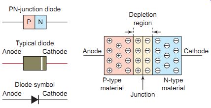
Ill. 1 PN-junction diode. Depletion region; Cathode; Junction N-type
material P-type material; Anode PN-junction diode Cathode Typical diode
Anode Cathode Diode symbol Anode PN
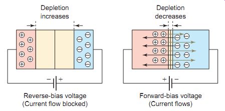
Ill. 2 Diode forward and reverse biasing. Depletion decreases Forward-bias
voltage (Current flows) ; Depletion increases Reverse-bias voltage (Current
flow blocked)
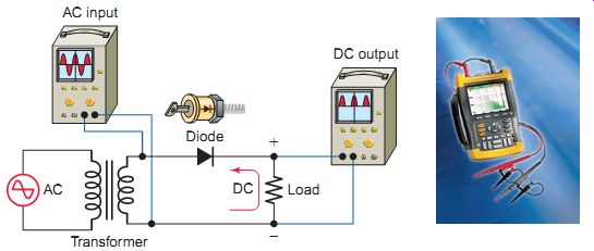
Ill. 3 Single-phase, half-wave rectifier circuit. Transformer
Rectifier Diode
Rectification is the process of changing AC to DC. Because diodes allow current to flow in only one direction, they are used as rectifiers. There are several ways of connecting diodes to make a rectifier to convert AC to DC. Ill. 3 shows the schematic for a single-phase, half-wave rectifier circuit. The operation of the circuit can be summarized as follows:
• The AC input is applied to the primary of the transformer; the secondary voltage supplies the rectifier and load resistor.
• During the positive half-cycle of the AC input wave, the anode side of the diode is positive.
• The diode is then forward-biased, allowing it to conduct a current to the load. Because the diode acts as a closed switch during this time, the positive half-cycle is developed across the load.
• During the negative half-cycle of the AC input wave, the anode side of the diode is negative.
• The diode is now reverse-biased; as a result, no cur rent can flow through it. The diode acts as an open switch during this time, so no voltage is produced across the load.
• Thus, applying an AC voltage to the circuit produces a pulsating DC voltage across the load.
Diodes can be tested for short-circuit or open-circuit faults with an ohmmeter. It should show continuity when the ohmmeter leads are connected to the diode in one direction but not in the other. If it does not show continuity in either direction, the diode is open. If it shows continuity in both directions the diode is short-circuited.
Inductive loads, such as the coils of relays and solenoids, produce a high transient voltage at turnoff. This inductive voltage can be particularly damaging to sensitive circuit components such as transistors and integrated circuits. A diode-clamping, or de-spiking, circuit connected in parallel across the inductive load can be used to limit the amount of transient voltage present in the circuit. The diode-clamping circuit of Ill. 4 illustrates how a diode can be used to suppress the inductive voltage of a relay coil. The operation of the circuit can be summarized as follows:
• The diode acts a one-way valve for current flow.
• When the limit switch is closed, the diode is reverse-biased.
• Electric current can't flow through the diode so it flows through the relay coil.
• When the limit switch is opened, a voltage opposite to the original applied voltage is generated by the collapsing magnetic field of the coil.
• The diode is now forward-biased and current flows through the diode rather than through the limit switch contacts, bleeding off the high-voltage spike.
• The faster the current is switched off, the greater is the induced voltage. Without the diode the induced voltage could reach several hundreds or even thou sands of volts.
• It’s important to note that the diode must be connected in reverse bias relative to the DC supply voltage. Operating the circuit with the diode incorrectly connected in forward bias will create a short circuit across the relay coil that could damage both the diode and the switch.
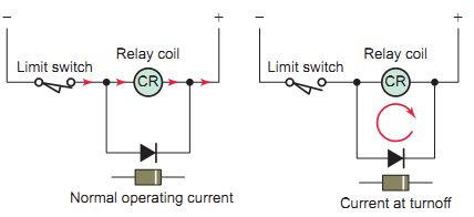
Ill. 4 Diode connected to suppress inductive voltage. Relay coil; Limit
switch; CR; Relay coil; Limit switch; Normal operating current; CR; Current
at turnoff
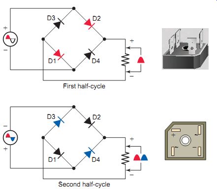
Ill. 5 Single-phase, full-wave bridge rectifier circuit. Fairchild Semiconductor,
fairchildsemi.com. Second half-cycle; First half-cycle
The half-wave rectifier makes use of only half of the AC input wave. A less-pulsating and greater average direct cur rent can be produced by rectifying both half-cycles of the AC input wave. Such a rectifier circuit is known as a full-wave rectifier. A bridge rectifier makes use of four diodes in a bridge arrangement to achieve full-wave rectification. This is a widely used configuration, both with individual diodes and with single-component bridges where the diode bridge is wired internally. Bridge rectifiers are used on DC injection braking of AC motors to change the AC line voltage to DC, which is then applied to the stator for braking purposes. The schematic for a single-phase, full-wave bridge rectifier circuit is shown in Ill. 5. The operation of the circuit can be summarized as follows:
• During the positive half-cycle, the anodes of D1 and D2 are positive (forward-biased), whereas the anodes of D3 and D4 are negative (reverse-biased). Electron flow is from the negative side of the line, through D1, to the load, then through D2, and back to the other side of the line.
• During the next half-cycle, the polarity of the AC line voltage reverses. As a result, diodes D3 and D4 become forward-biased. Electron flow is now from the negative side of the line through D3, to the load, then through D4, and back to the other side of the line. Note that during this half-cycle the current flows through the load in the same direction, producing a full-wave pulsating direct current.
Some types of direct current loads such as motors, relays, and solenoids will operate without problems on pulsating DC, but other electronic loads will not. The pulsations, or ripple, of the DC voltage can be removed by a filter circuit. Filter circuits may consist of capacitors, inductors, and resistors connected in different configurations. The schematic for a simple half-wave capacitor filter circuit is shown in Ill. 6. Filtering is accomplished by alternate charging and discharging of the capacitor. The operation of the circuit can be summarized as follows:
• The capacitor is connected in parallel with the DC output of the rectifier.
• With no capacitor, the voltage output is normal half-wave pulsating DC.
• With the capacitor installed, on every positive half cycle of the AC supply, the voltage across the filter capacitor and load resistor rises to the peak value of the AC voltage.
• On the negative half-cycle, the charged capacitor provides the current for the load to provide a more constant DC output voltage.
• The variation in the load voltage, or ripple, is dependent upon the value of the capacitor and load.
A larger capacitor will have less voltage ripple.
For heavier load demands, such as those required for industrial applications, the DC output is supplied from a three-phase source. Using three-phase power, it’s possible to obtain a low-ripple DC output with very little filtering. Ill. 7 shows a typical three-phase full-wave bridge rectifier circuit. The operation of the circuit can be summarized as follows:
• The six diodes are connected in a bridge configuration, similar to the single-phase rectifier bridge to produce DC.
• The cathodes of the upper diode bank connect to the positive DC output bus.
• The anodes of the lower diode bank connect to the negative DC bus.
• Each diode conducts in succession while the remaining two are blocking.
• Each DC output pulse is 60° in duration.
• The output voltage never drops below a certain voltage level.
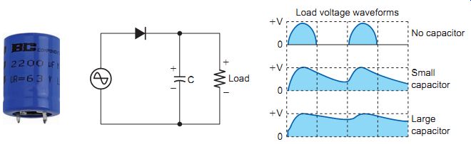
Ill. 6 Capacitor filter. No capacitor; Load voltage waveforms; Small
capacitor; Large capacitor
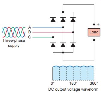
Ill. 7 Three-phase, full-wave bridge rectifier. DC output voltage waveform;
Three-phase supply; Load
Zener Diode
A zener diode is a type of diode that permits current to flow in the forward direction like a standard diode, but also in the reverse direction if the voltage is larger than the breakdown voltage, known as the zener voltage. This reverse-bias current would destroy a standard diode, but the zener diode is designed to handle it. The specified zener voltage rating of a zener diode indicates the volt age at which the diode begins to conduct when reverse biased.
Zener diodes are used to provide a fixed reference volt age from a supply voltage that varies. They are commonly found in motor control feedback systems to provide a fixed level of reference voltage in regulated power supply circuits. Ill. 8 shows a typical zener diode regulator circuit. The operation of the circuit can be summarized as follows:
• Input voltage must be higher than the specified zener voltage.
• The zener diode is connected in series with the resistor to allow enough reverse-biased current to flow for the zener to operate.
• Voltage drop across the zener diode will be equal to the zener diode's voltage rating.
• Voltage drop across the series resistor is equal to the difference between the zener voltage and the input voltage.
• The zener diode's voltage remains constant as the input voltage changes within a specified range.
• The change in input voltage appears across the series resistor.
Two back-to-back zener diodes can suppress damaging voltage transients on an AC line. A metal oxide varistor (MOV) surge suppressor functions in the same manner as back-to-back zener diodes. The circuit of Ill. 9 is used to suppress AC voltage transients. The varistor module shown is made to be easily mounted directly across the coil terminals of contactors and starters with 120 V or 240 V AC coils. The operation of the circuit can be summarized as follows:
• Each zener diode acts as an open circuit until the reverse zener voltage across it exceeds its rated value.
• Any greater voltage peak instantly makes the zener diode act like a short circuit that bypasses this volt age away from the rest of the circuit.
• It’s recommended that you locate the suppression device as close as possible to the load device.
Light-Emitting Diode
The light-emitting diode (LED) is another important diode device. An LED contains a PN junction that emits light when conducting current. When forward-biased, the energy of the electrons flowing through the resistance of the junction is converted directly to light energy.
Because the LED is a diode, current will flow only when the LED is connected in forward-bias. The LED must be operated within its specified voltage and current ratings to prevent irreversible damage. Ill. 10 illustrates a simple LED circuit. The LED is connected in series with a resistor that limits the voltage and current to the desired value.
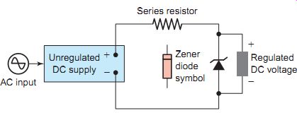
Ill. 8 Typical zener diode regulator circuit. AC input; Series resistor;
Unregulated; DC supply; Zener diode symbol; Regulated; DC voltage
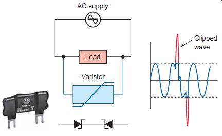
Ill. 9 Suppressing AC voltage transients. Varistor; AC supply; Load
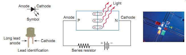
Ill. 10 Light-emitting diode (LED). Cathode Anode; Long lead anode;
Series resistor; Light Anode PN; Cathode
The main advantages of using an LED as a light source rather than an ordinary light bulb are a much lower power consumption, a much higher life expectancy, and high speed of operation. Conventional silicon diodes convert energy to heat. Gallium arsenide diodes convert energy to heat and infrared light. This type of diode is called an infrared-emitting diode (IRED). Infrared light is not visible to the human eye. By doping gallium arsenide with various materials, LEDs with visible outputs of red, green, yellow, or blue light can be manufactured. Light-emitting diodes are used for pilot lights and digital displays. Ill. 11 shows a typical seven-segment LED numerical display. By energizing the correct segments, the numbers 0 through 9 can be displayed.
Photodiodes
Photodiodes are PN-junction diodes specifically designed for light detection. They produce current flow when they absorb light. Light energy passes through the lens that exposes the junction. The photodiode is designed to operate in the reverse-bias mode. In this device, the reverse-bias leakage current increases with an increase in the light level. Thus, a photodiode exhibits a very high resistance with no light input and less resistance with light input.
There are many situations where signals and data need to be transferred from one piece of equipment to another, without making a direct electrical connection. Often this is because the source and destination are at very different voltage levels, like a microprocessor that is operating from 5 V DC but is being used to control a circuit that is switching 240 V AC. In such situations the link between the two must be an isolated one, to protect the microprocessor from overvoltage damage.
The circuit of Ill. 12 uses a photodiode as part of an optocoupler (also known as an optoisolator) pack age containing an LED and a photodiode. Optocouplers are used to electrically isolate one circuit from another. The only thing connecting the two circuits is light, so they are electrically isolated from each other.
Optocouplers typically come in a small integrated circuit package and are essentially a combination of an optical transmitter LED and an optical receiver such as a photodiode. The operation of the circuit can be summarized as follows:
• The LED is forward-biased, while the photodiode is reverse-biased.
• With the push button open, the LED is off. No light enters the photodiode and no current flows in the input circuit.
• The resistance of the photodiode is high, so little or no current flows through the output circuit.
• When the input push button is closed, the LED is forward-biased and turns on.
• Light enters the photodiode so its resistance drops switching on current to the output load.
QUIZ
1. Compare the type of current carriers associated with N-type and P-type semiconductor materials.
2. State the basic operating characteristic of a diode.
3. How is a diode tested using an ohmmeter?
4. What determines whether a diode is forward- or reverse-biased?
5. Under what condition is a diode considered to be connected in forward bias?
6. What is the function of a rectifier diode?
7. Explain the process by which a single-phase half wave rectifier changes AC to DC.
8. What is the purpose of a clamping, or despiking, diode?
9. A single-phase half-wave rectifier is replaced with a full-wave bridge type. In what ways will the DC output change?
10. How does a capacitor filter operate to smooth the amount of pulsation (ripple) associated with rectifier circuits?
11. What advantages are gained by using three-phase rectifiers over single-phase types?
12. In what way is the operation of a zener diode different from that of a standard diode?
13. Zener diodes are commonly used in voltage regulation circuits. What operating characteristic of the zener diode makes it useful for this type of application?
14. State the basic operating principle of an LED.
15. How many LEDs are integrated into a single LED numerical display?
16. Explain how a photodiode is designed to detect light.
Cont. to part b