AMAZON multi-meters discounts AMAZON oscilloscope discounts
GOALS:
1. Understand the recommended procedure for a basic motor installation based on NEC Article 430.
2. List and describe the methods by which a motor can be started.
3. Comprehend the operation of reversing and jogging motor control circuits.
4. List and describe the methods of stopping a motor.
5. Comprehend the operation of basic speed control circuits.
This section is intended to give students an insight into properly designed, coordinated, and installed motor control circuits. Topics covered include installation requirements of the NEC and motor starting, stopping, reversing, and speed control.

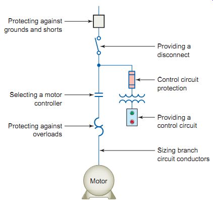
Ill. 1 Basic elements of a motor branch circuit that the NEC addresses.
Protecting against overloads; Selecting a motor controller; Protecting
against grounds and shorts; Sizing branch circuit conductors Providing
a control circuit; Control circuit protection; Providing a disconnect;
Motor
NEC Motor
Installation Requirements
Understanding the rules detailed in the National Electrical Code (NEC) is critical to the proper installation of motor control circuits. NEC
Article 430 covers application and installation of motor circuits including conductors, short-circuit and ground fault protection, starters, disconnects, and overload protection. Ill. 1 illustrates the basic elements of a motor branch circuit that the NEC addresses. A motor branch circuit includes the final overcurrent device (disconnect switch and fuses or circuit breaker), the motor starter and associated control circuits, circuit conductors, and the motor.
Sizing Motor Branch Circuit Conductors
Installation requirements for motor branch circuit conductors are outlined in NEC Article 430, Part II . Generally, motor branch circuit conductors that supply a single motor used in a continuous-duty application must have an ampacity of not less than 125 percent of the motor's full-load current (FLC) rating as determined by Article 430.6. This provision is based on the need to provide for a sustained running cur rent that's greater than the rated full-load current and for protection of the conductors by the motor overload protective device set above the full-load current rating.
The full-load current rating shown on the motor name plate isn’t permitted to be used to determine the ampacity of the conductors, the ampacity of switches, or motor branch-circuit short-circuit and ground fault protection.
The reasons for this are:
• The supply voltage normally varies from the voltage rating of the motor, and the current varies with the voltage applied.
• The actual full-load current rating for motors of the same horsepower may vary, and requiring the use of NEC tables ensures that if a motor must be replaced, this can be safely done without having to make changes to other component parts of the circuit.
Conductor ampacity must be determined by NEC Tables 430.247 through 430.250 and is based on the motor nameplate horsepower rating and voltage. Overload protection, however, is based on the marked motor nameplate rating. Use of the term full-load current (FLC) rating indicates the table rating while use of the term full-load ampere ( FLA) rating indicates the actual nameplate rating. This makes it easier to clarify whether the table ampacity or the nameplate ampacity is being used.
EXAMPLE:
Problem: Three 460-V, three-phase motors rated at 50, 30, and 10 hp share the same feeder. Using your edition of the NEC, determine the ampacity required to size the feeder conductors.
Solution:
50-hp motor-NEC Table 430.250 shows the FLC as 65 A. 400-V, three-phase feeder conductors Motor starter panel 50 hp 30 hp 10 hp
Ill. 2 Circuit E.g.. 30-hp motor-NEC Table 430.250 shows the FLC as
40 A. 10-hp motor-NEC Table 430.250 shows the FLC as 14 A. Therefore,
the required ampacity of the feeder conductors is (1.25)(65) + 40 +14
= 135.25 A.
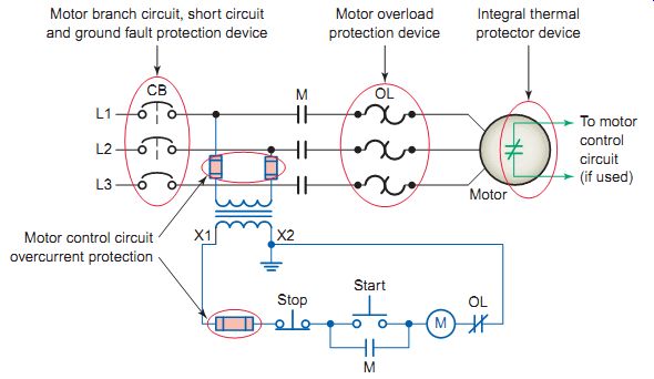
Ill. 3 Motor branch circuit protection. Motor control circuit overcurrent
protection. Motor branch circuit, short circuit and ground fault protection
device; Motor overload protection device; Integral thermal protector device;
To motor control circuit (if used)
EXAMPLE:
Problem:
Using your edition of the NEC, determine the mini mum branch-circuit conductor ampacity required for each of the following motors:
a. 2-hp, 230-V, single-phase motor
b. 30-hp, 230-V, three-phase motor with a name plate FLA rating of 70 A
Solution:
a. NEC Table 430-248 shows the FLC as 12 A. Therefore, the conductor ampacity required is 12 × 125% = 15 A.
b. NEC Table 430.250 shows the FLC as 80 A. Therefore, the conductor ampacity required is 80 × 125% = 100 A.
Feeder conductors supplying two or more motors must have an ampacity not less than 125 percent of the full-load current rating of the highest-rated motor plus the sum of the full-load current ratings of the other motors supplied. When two or more motors of equal rating are on a feeder, one of the motors will be considered the largest and calculated at 125 percent, and the others will be added at 100 percent.
Once the required ampacity of the conductor has been determined, NEC Table 310.16 can be used to determine the American Wire Gauge (AWG) or thousand circular mil (kcmil) size of conductor required. NEC Table 310.16 applies to situations where you have three or less current-carrying conductors in a single wireway. You must select from the column that shows the cable (identified by the insulating material letter designation) you intend to use, and choose between copper and aluminum. Bear in mind that all calculated conductor sizes based on ampacity are minimum, taking into consideration temperature rise only. The calculations don’t take into account voltage dip during motor starting or volt age drop during motor running. Such considerations often require increasing the size of the branch circuit conductors.
Branch Circuit Motor Protection
Overcurrent protection for motors and motor circuits is a little different from that for nonmotor loads. The most common method for providing overcurrent protection for nonmotor loads is to use a circuit breaker that combines overcurrent protection with short-circuit and ground fault protection. However, this isn't usually the best choice for motors because they draw a large amount of current at initial start-up, usually around 6 times the normal full-load current of the motor.
With rare exceptions, the best method for providing overcurrent protection for motors is to separate the overload protection devices from the short-circuit and ground fault protection devices, as illustrated in Ill. 3. Motor overload protection devices like heaters and integral thermal devices protect the motor, the motor control equipment, and the branch circuit conductors from motor overload and the resultant excessive heating. They don't provide protection against short-circuit or ground fault currents. That's the job of the branch and feeder breakers. This arrangement makes motor calculations different from those used for other types of loads.
NEC Article 430, Part IV explains the requirements for branch circuit short-circuit and ground fault protection. The NEC requires that branch circuit protection for motor circuits must protect the circuit conductors, the control apparatus, as well as the motor itself against overcurrent due to short circuits or ground faults. The protection device (circuit breaker or fuse) for an individual branch circuit to a motor must be capable of carrying the starting current of the motor without opening the circuit. The Code places maximum values on the ratings or setting of these devices, as found in Table 430.52. A protective device that has a rating or setting not exceeding the value calculated according to the values given in Table 430.52 must be used. In cases where the values don’t correspond to the standard sizes of fuses, to the ratings of nonadjustable circuit breakers, or to possible set tings of adjustable circuit breakers, and the next lower value isn’t adequate to carry the motor load, the next higher size, rating, or setting may be used. The standard sizes of fuses and breakers are listed in NEC Article 240.6.
An instantaneous trip circuit breaker responds to a predetermined value of overload without any purposely delayed action. Most circuit breakers have an inverse time-delay characteristic. With an inverse time circuit breaker the higher the overcurrent, the shorter the time required for the breaker to trip and open the circuit.
Non-time-delay fuses provide excellent short-circuit protection. When an overcurrent occurs, heat builds up rapidly in the fuse. Non-time-delay fuses usually hold about 5 times their rating for approximately ¼ second, after which the current-carrying element melts. Time delay fuses provide overload and short-circuit protection.
Time-delay fuses usually allow 5 times the rated current for up to 10 seconds to allow motors to start.
NEC Article 430, Part III deals with motor and branch circuit overload protection. A motor overload condition is caused by excessive load applied to the motor shaft. E.g., when a saw is used, if the board is damp or the cut is too deep, the motor may become overloaded and slow down. The current flow in the windings will increase and heat the motor beyond its design temperature. A jammed pump or an extra-heavy load on a hoist will have the same effect on a motor. The overload protection also guards against failure of a motor to start from a locked rotor and loss of a phase on a three-phase system. Overload protection isn’t designed to break or may not be capable of breaking short-circuit current or ground fault current.
Motors are required to have overload protection, either within the motor itself or somewhere in close proximity to the line side of the motor. This overload protection is actually protecting the motor, the conductors, and much of the circuit ahead of the overloads. An overload in the circuit will trip the circuit overload devices, thus protecting the circuit from overload conditions. In the majority of applications, overcurrent protection is provided by the overload relays in the motor controller. All three-phase motors, except those protected by other approved means, such as integral-type detectors, must be provided with three overload units, one in each phase.
The nameplate full-load ampere ( FLA) rating of the motor, rather than NEC tables, is used for sizing the overloads for the motor. Using this data, tables supplied by the starter manufacturer are consulted to find the correct overload relay thermal heater unit for the particular overload relay in use.
A separate overload device that's responsive to motor cur rent is required by NEC Article 430.32. This device shall be selected to trip or shall be rated at not more than 125 percent of the motor nameplate full-load current rating. When the thermal element selected in accordance with NEC 430.32 isn’t sufficient to start the motor or to carry the load, a higher size thermal element can be used, provided the trip current of the overload relay doesn’t exceed 140 percent of the motor nameplate full-load current rating.
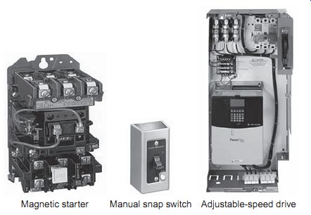
Ill. 4 Examples of motor controllers. Magnetic starter; Manual snap switch;
Adjustable-speed drive
EXAMPLE:
Problem:
Determine the size of inverse time circuit breaker per mitted to be used to provide motor branch circuit short circuit and ground fault protection for a 10-hp, 208-V, three-phase squirrel-cage motor.
Solution:
NEC Table 430.250 shows the motor FLC as 30.8 A.
NEC Table 430.52 shows the maximum rating for an inverse time breaker as 250 percent of the FLC.
30.8 × 2.5 = 77 A
Because this isn’t a standard size, 80 A may be used if a 70-A inverse time circuit breaker isn’t adequate.
Motor control circuits carry the current that controls the operation of the controller, but don’t carry the main power current to the motor. These circuits are permitted to be tapped from the motor branch circuit conductors or supplied from a separate source. NEC 430.72 deals with overcurrent protection of motor control circuits tapped from the motor branch circuit and NEC 725.23 is used for those from other sources of power. Where a lower voltage is desired, a control transformer may be installed in either of the two supply methods used.
Selecting a Motor Controller
A motor controller is any device that's used to directly start and stop an electric motor by closing and opening the main power current to the motor. The controller can be a switch, starter, or other similar type of control device. Examples of motor controllers are illustrated in Ill. 4. A magnetic starter consisting of a contactor and overload relay is considered to be a controller.
A properly rated snap switch that's permitted to turn a single-phase motor on and off is also considered to be a motor controller. Snap switches are permitted to serve as the motor controller as well as the disconnecting means.
A solid-state starter or an AC or DC drive is also classified as a motor controller. With solid-state controllers, it’s the power-circuit element, such as a triac or SCR, that meets the definition of controller.
The rating of the motor controller or starter is directly related to its NEMA size, with the electrical ratings of each being provided by the manufacturer's data sheets.
A controller enclosure must be marked with the manufacturer's identification, the voltage rating, the current rating, or the horsepower rating. NEC Article 430, Part VII details the requirements for motor controllers. The following are some of the highlights of this section.
• The branch circuit and ground fault device can be used as the controller for stationary motors of 1/8 hp or less that are not normally left running and cannot be damaged by overload or failure to start.
A good example of this would be a clock motor.
• An attachment plug and receptacle can be used as a controller for a portable motor of 1/3 hp or less.
• A controller must be capable of starting and stop ping the motor it controls as well as able to interrupt the locked-rotor current of the motor.
• Unless an inverse-time circuit breaker or molded case switch is used, controllers must have horse power rating at the applied voltage not lower than the horsepower rating of the motor.
• For stationary motors rated at 2 hp or less and 300 V or less, the controller can be either of the following:
1. A general-use switch having an ampere rating not less than twice the full-load current rating of the motor.
2. On AC circuits, a general-use snap switch suit able only for use on AC (not general use AC/DC snap switches) where the full-load current rating isn’t more than 80 percent of the amperage rating of the switch.
• A controller that doesn’t also serve as a disconnecting means must open only as many motor circuit conductors as may be necessary to stop the motor, that's , one conductor for DC or single-phase motor circuits and two conductors for a three-phase motor circuit.
• Individual controllers must be provided for each motor unless the motor is under 600 V, or there is a single machine with several motors, or a single overcurrent device, or a group of motors located in a single room within sight of the controller.
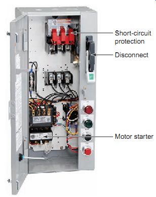
Ill. 5 Combination fused-switch, magnetic starter unit. Short-circuit
protection; Disconnect; Motor starter
Disconnecting Means for Motor and Controller
The ability to safely work on a motor, a motor controller, or any motor-driven machinery starts with being able to turn the power off to the motor and its related equipment.
NEC Article 430, Part IX covers the requirements for the motor disconnecting means. The Code requires that a means (a motor circuit switch rated in horsepower or a circuit breaker) must be provided in each motor circuit to disconnect both the motor and its controller from all ungrounded supply conductors. All disconnecting switches must plainly indicate whether they are open (off) or closed (on) and no pole is allowed to operate independently. Separate disconnects and controllers may be mounted on the same panel or contained in the same enclosure, such as a combination fused-switch, magnetic starter unit.
The disconnecting means other than the branch circuit short-circuit and ground fault protective device is used as a safety switch to disconnect the motor circuit. It should be in sight of the motor and can be unfused. If a person is working on the motor, the disconnect will be where he or she can see it; that protects the person from a motor accidentally starting. If the branch circuit short-circuit and ground fault protective device is used as a disconnecting means and isn’t within sight of the motor, it must be capable of being locked in the open position. The NEC defines "within sight" as being visible and not more than 50 ft (15 m) distant from the other as illustrated in Ill. 6.
For motor circuits rated at 600 V or less, the disconnecting means must be at least 115 percent of the full-load rating (FLC) of the motor. The disconnecting means can be branch circuit fuses or circuit breakers. Motor disconnect switches are rated in volts, amperes, and horsepower.
If rated in horsepower, the disconnect switch must have a horsepower rating equal to, or greater than, the horse power rating of the motor at the valid voltage. For stationary motors rated more than 40 hp DC or 100 hp AC, a general-use or isolating switch can be used but must be plainly marked “DO NOT OPERATE UNDER LOAD." An isolating switch is intended to isolate an electric circuit from its source of power; it has no interrupting rating and is intended to be operated only after the circuit has been opened by some other means.
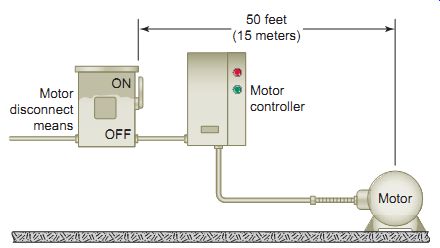
Ill. 6 The disconnecting means must be located within sight from the
controller, motor, and the driven machinery location. Motor > Motor
controller > ON/OFF > Motor disconnect means 50 feet (15 meters)
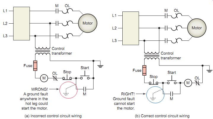
Ill. 7 The design of the control circuit must prevent the motor from
being started by a ground fault in the control circuit wiring. WRONG!
A ground fault anywhere in the hot leg could start the motor. RIGHT! Ground
fault cannot start the motor. (a) Incorrect control circuit wiring (b)
Correct control circuit wiring
Providing a Control Circuit
EXAMPLE:
Problem:
Determine the current rating of the motor disconnect switch required for a 460-V, three-phase, 125-hp motor.
Solution:
NEC Table 430.250 shows the motor FLC as 156 A.
NEC 430.110 requires the motor disconnecting means to have an ampere rating of at least 115 per cent of the FLC rating of the motor.
156 A × 1.15 = 179 A
Therefore a 200-A disconnect switch is required.
A motor control circuit carries electrical signals directing the action of the controller but doesn’t carry the main power circuit. The control circuit commonly has as its load device the operating coil of a magnetic motor starter, a magnetic contactor, or a relay. NEC Article 430, Part VI covers the requirements for motor control circuits. Control circuits associated with motor controls can be extremely complex and vary greatly with application. The elements of a control circuit include all the equipment and devices concerned with the function of the circuit: conductors, race way, contactor operating coil, source of energy supply to the circuit, overcurrent protection devices, and all switching devices that govern energization of the operating coil.
Motor control circuits can be the same voltage as the motor up to 600 V, or can be reduced by means of a control transformer. Often a control transformer is used, especially when the control circuit extends beyond the controller. E.g., a 460-V motor with an external 120-V control circuit's much easier and safer to deal with.
Where one side of the motor control circuit's grounded, the design of the control circuit must prevent the motor from being started by a ground fault in the control circuit wiring. This rule must be observed for any control circuit that has one leg grounded. If one side of the start button is in the ground leg of the circuit, as shown in Ill. 7a, a ground fault on the coil side of the start button can short circuit the start circuit and start the motor. By switching the hot leg, as shown in Ill. 7b, the starting of the • Where the motor control circuit's supplied from a source other than the motor branch circuit, the motor control circuit disconnecting means must be located immediately adjacent to the controller disconnecting means.
• Where a transformer is used to obtain a reduced voltage for the motor control circuit and the transformer is located within the motor controller enclosure, the transformer must be connected to the load side of the motor control circuit disconnecting means. The control transformer must be protected in accordance with NEC Article 430.72. motor by an accidental ground fault can be effectively eliminated. Another requirement for control circuits is that a ground fault won’t bypass manual shutdown devices or automatic safety shutdown devices.
NEC Article 430.74 requires that motor control circuits be arranged so that they will be disconnected from all sources of supply when the disconnecting means is in the open position.
• Where the motor control circuit's supplied from the motor branch circuit, the controller disconnecting means may serve as the motor control circuit disconnecting means.
QUIZ
1. List seven basic elements of a motor branch circuit that Article 430 of the NEC addresses.
2. Give two reasons why motor branch circuit conductors are required to have an ampacity not less than 125 percent of the motor FLC.
3. Compare the terms of reference used in defining the terms FLC and FLA.
4. Determine the FLC and the ampacity required to size a 15-hp, 575-V, three-phase motor squirrel-cage motor.
5. Two 25-hp, 460-V, three-phase motors share the same feeder. What is the ampacity needed to size the feeder conductors?
6. Two 30-hp motors and a 40-hp motor, all 460-V, three-phase, continuous-duty squirrel-cage motors, are on a single feeder.
a. What is the ampacity needed to size the feeder conductors?
b. What size THWN copper conductors are required?
7. In what way are motor load characteristics different from those of general lighting and other loads?
8. Compare the type of branch overcurrent protection used for nonmotor and motor loads.
9. A 460-V, three-phase, 30-hp motor is to be short circuit and ground fault-protected by non-time delay fuses.
a. What is the full-load current of this motor according to Table 430.250?
b. What is the maximum fuse rating required according to Table 430.52?
c. What standard fuse size, according to Article 240.6, would be selected?
10. Compare the operation of instant trip and inverse time circuit breakers.
11. Compare the operation of non-time-delay and time delay fuses.
12. List three things motor overload protection guards against.
13. How many overload units are required for a three phase motor?
14. Explain the procedure followed in selecting the size of the thermal heating elements for a given motor and starter.
15. List three common types of motor controllers.
16. How is a controller sized relative to the motor horsepower rating?
17. An attachment plug and receptacle can be used as a controller for what type of motor?
18. What is the basic rule with regard to location of the motor disconnecting means?
19. What provisions must be made if the branch circuit short-circuit and ground fault protective device is used as the disconnecting means and isn’t within sight of the motor?
20. Determine the current rating of the motor disconnect switch required for a 460-V, three-phase, 40-hp motor.
21. List three devices that commonly serve as the load for a motor control circuit.
22. What safety issues must be addressed in the design of a motor control circuit when one side of the control circuit's grounded?
Cont. to part b