AMAZON multi-meters discounts AMAZON oscilloscope discounts
Cont. from part a
Motor Starting
Every motor, when turning, acts somewhat like a genera tor. This generator action produces a voltage opposite, or opposed to, the applied voltage that reduces the amount of current supplied to the motor. The voltage generated in a motor is called counter emf (cemf) and results from the rotor cutting through magnetic lines of force.
When the motor is being started and before it has begun to turn, however, there is no cemf to limit the current, so initially there is a high starting, or locked-rotor, current.
The term locked-rotor current is derived from the fact that its value is determined by locking the motor shaft so that it cannot turn, then applying rated voltage to the motor, and measuring the current. Although the starting current may be up to 6 times the normal running current, it normally lasts for only a fraction of a second (Ill. 8).
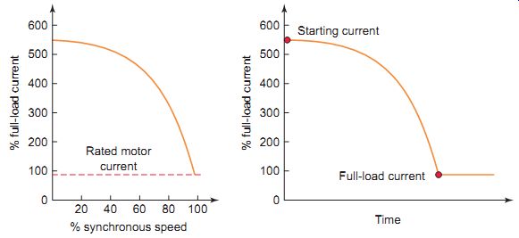
Ill. 8 Starting current is reduced as the motor accelerates. Rated motor
current; Full-load current; Starting current; % full-load current % full-load
current; % synchronous speed
The main factor in determining the amount of counter generated voltage and current in the motor is its speed.
Therefore, all motors tend to draw much more current during the starting period (starting current) than when rotating at operating speed (running current). If the load placed on a motor reduces the speed, less generated cur rent will be developed and more applied current will flow.
That is, the greater the load on the motor, the slower the motor will rotate and the more applied current will flow through its windings. If the motor is jammed or prevented from rotating in any way, a locked-rotor condition is created, and the applied current becomes very high. This high current will cause the motor to burn out quickly.
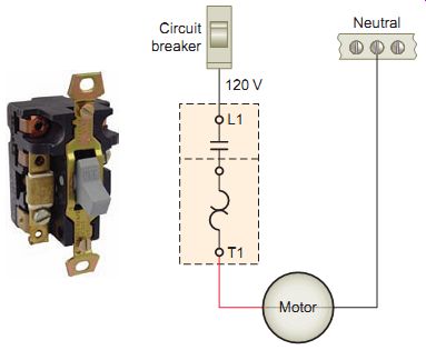
Ill. 9 Single-pole fractional horsepower manual starter. From Schneider
Electric.
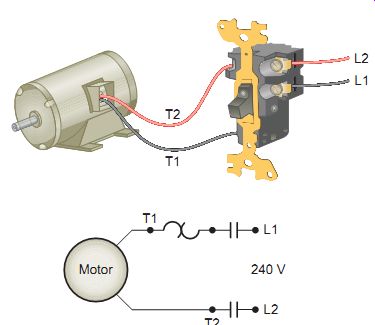
Ill. 10 Double-pole manual motor starter.
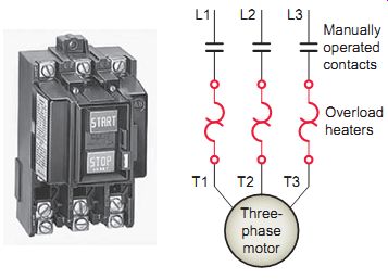
Ill. 11 Three-pole manual starter.
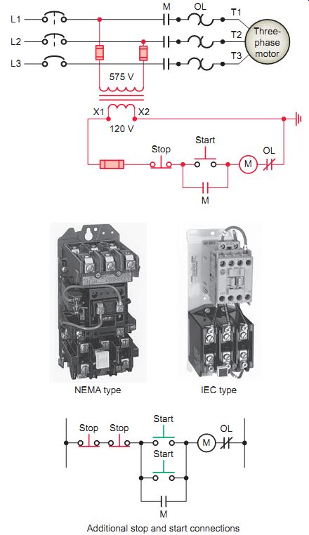
Ill. 12 Typical magnetic across-the-line starter. Additional stop and
start connections
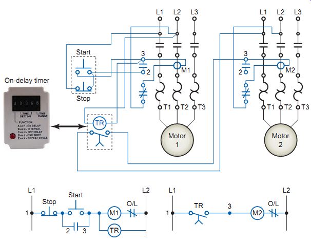
Ill. 13 Timed starting of two motors.
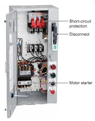
Ill. 14 Combination starter. Short-circuit protection Disconnect Motor
starter
Full-Voltage Starting of AC Induction Motors
A full-voltage, or across-the-line, starter is designed to apply full line voltage to the motor upon starting. If the high starting current doesn’t affect the power supply sys tem and the machinery will stand the high starting torque, then full-voltage starting may be acceptable. Full-voltage starters may be either manual or magnetic. Manual motor starters are hand-operated and consist of an on/off switch with one set of contacts for each phase and motor overload protection. Since no electrical closing coil is used, the starter's contacts remain closed during a power interruption.
When power is restored, the motor immediately restarts.
Manual starters for fractional-horsepower, single-phase motors are found in a variety of residential, commercial, and industrial applications. Ill. 9 shows a single-pole fractional horsepower manual motor starter consisting of a manually operated on/off snap-action switch with over load protection. When the switch is moved to the on or start position, the motor is connected directly across the line and in series with the starter contact and the thermal overload (OL) protection device. As more current flows through the circuit, the temperature of the thermal overload rises, and at a predetermined temperature point, the device actuates to open the contact. When an overload is sensed, the starter handle automatically moves to the center position to signify that the contacts have opened because of overload and the motor is no longer operating. The starter contacts cannot be reclosed until the overload relay is reset manually. The starter is reset by moving the handle to the full off position after allowing about two minutes for the heater to cool.
Manual motor starters are available in single-pole, double-pole, and three-pole designs. Ill. 10 shows a double-pole manual motor starter with a single overload heater to protect the motor windings. Line-rated control devices such as thermostats, float switches, and relays are used to connect and disconnect the motor when automatic operation is desired.
The three-pole manual starter shown provides three overload heaters to protect the motor windings. This starter is operated by pushing a button on the starter enclosure cover that mechanically operates the starter. When an overload relay trips, the starter mechanism unlatches, opening the contacts to stop the motor.
The contacts cannot be reclosed until the starter mechanism has been reset by pressing the stop button; first, how ever, the thermal unit needs time to cool. These starters are designed for infrequent starting of small AC motors (10 hp or less) at voltages ranging from 120 to 600 V.
The power circuit contacts of manual motor starters are unaffected by the loss of voltage, so consequently will remain in the closed position when the supply voltage fails. When the motor is running and the supply voltage fails, the motor will stop and restart automatically when the supply voltage is restored. This places these starters in the classification of no-voltage release. Also, manual starters must be mounted near the motor that's being controlled. Remote control operation isn’t possible as it would be with a magnetic starter.
Unlike the manual starter in which the power contacts are closed manually, the magnetic starter motor starter contacts are closed by energizing a holding coil. This enables the use of automatic and remote control of the motor. With magnetic control, pushbutton stations are mounted nearby, but automatic control pilot devices can be mounted almost anywhere on the machine.
Ill. 12 shows a typical three-phase magnetic across-the-line AC starter diagram. The circuit's operation can be summarized as follows:
• The control transformer is powered by two of the three phases. This transformer lowers the voltage to a more common value useful when adding lights, timers or remote switches not rated for the higher voltages.
• When the start button is pressed, coil M energizes to close all M contacts. The M contacts in series with the motor close to complete the current path to the motor. These contacts are part of the power circuit and must be designed to handle the full-load current of the motor. Memory contact M (connected across the start button) also closes to seal in the coil circuit when the start button is released. This contact is part of the control circuit; as such, it’s required to handle the small amount of current needed to energize the coil.
• The starter has three overload heaters, one in each phase.
The normally closed (NC) relay contact OL opens automatically when an overload current is sensed on any phase to deenergize the M coil and stop the motor.
• The motor can be started or stopped from a number of locations by connecting additional start buttons in parallel and additional stop buttons in series.
• These starters are available in both IEC and NEMA ratings.
The circuit of Ill. 13 is used to start two motors at full line voltage. In order to reduce the amount of starting current, the circuit has been designed so that there will be a short time delay period between the starting of motor 1 and motor 2. Its operation can be summarized as follows:
• The first motor is started by pressing the start button connected in a three-wire control configuration to motor starter M1.
• Power is applied to both motor 1 and on-delay timer coil TR.
• After the preset time, the normally open timer contacts on TR close to energize starter coil M2 and the second motor starts.
• Both motors can be stopped by pressing the stop button.
The NEC requires all motors to have a disconnecting means designed to disengage power to the motor or motor starter. A combination starter, such as shown in Ill. 14, consists of a safety switch and a magnetic motor starter placed in a common enclosure. The cover of the enclosure is interlocked with the external operating handle of the disconnect means. The door cannot be opened while the disconnect means is closed. When the disconnect means is open, all parts of the starter are accessible; however, the hazard is reduced because the readily accessible parts of the starter are not connected to the power line. Pilot devices such as pushbutton and indicator lights may also be mounted on the panel. Combination starters offer space and cost savings over the use of separate components.
==
Starting method; Full voltage; Autotransformer 80% tap 65% tap 50% tap Part-winding Star delta Solid-state
% voltage at motor terminals
Motor starting current as a percent of:
Line current as a percent of:
Motor starting torque as a percent of:
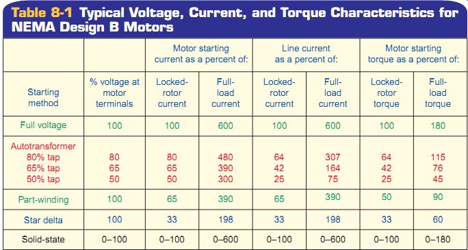
Table 1 Typical Voltage, Current, and Torque Characteristics for NEMA
Design B Motors
==
Reduced-Voltage Starting of Induction Motors
There are two primary reasons for using a reduced voltage in starting a motor:
• It limits line disturbances.
• It reduces excessive torque to the driven equipment.
When a motor is started at full voltage, the current drawn from the power line is typically 600 percent of normal full-load current. The large starting inrush cur rent of a big motor could cause line voltage dips and brownout. In addition to high starting currents, the motor also produces starting torques that are higher than full load torque. In many applications this starting torque can cause mechanical damage such as belt, chain, or coupling breakage. When a reduced voltage is applied to a motor at rest, both the current drawn by the motor and the torque produced by the motor are reduced. Table 1 shows the typical relationship of voltage, current, and torque for a NEMA design B motor.
Electric utility current restrictions, as well as in-plant bus capacity, may require motors above a certain horse power to be started with reduced voltage. High-inertia loads may require control of the acceleration of the motor and load. If the driven load or the power distribution system cannot accept a full-voltage start, some type of reduced voltage or soft starting scheme must be used. Typical reduced-voltage starters include primary resistance starters, autotransformers, wye-delta starters, part-winding starters, and solid-state starters. These devices can be used only where low starting torque is acceptable.
PRIMARY-RESISTANCE STARTING
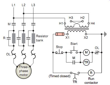
Ill. 15 Primary resistance starter.
Reduced voltage is obtained in the primary-resistance starter by means of resistances that are connected in series with each motor stator lead during the starting period. The voltage drop in the resistors produces a reduced voltage at the motor terminals. At a definite time after the motor is connected to the line through the resistors, timer contacts close; this short-circuits the starting resistors and applies full voltage to the motor. Typical applications include conveyors, belt-driven equipment, and gear-driven equipment.
Ill. 15 shows a typical primary-resistance reduced-voltage starter. Its operation can be summarized as follows:
• Pressing the start push button energizes motor starter coil M and timer coil TR. The motor is initially then started through a resistor in each of the three incoming lines. Part of the line voltage is dropped through the resistors with the motor receiving about 75 to 80 percent of the full line voltage.
• As the motor picks up speed, the motor sees more of the line voltage.
• At a preset time the timer on-delay contacts close to energize contactor C coil. This causes contacts C to close, shorting out the resistors and applying full voltage to the motor. The resistors' value is chosen to provide adequate starting torque while minimizing starting current.
• Improved starting characteristics with some loads can be achieved by the use of several stages of resistance shorting. This type of reduced voltage starting is limited by the amount of heat the resistors can dissipate.
AUTOTRANSFORMER STARTING
Instead of resistors, autotransformer starting uses a step down autotransformer (single-winding transformer) to reduce the line voltage. Autotransformer starters offer the greatest reduction of line current of any reduced-voltage starting method. Multiple taps on the transformer permit the voltage, current, and torque to be adjusted to satisfy many different starting conditions. In closed transition starting, the motor is never disconnected from the line source during acceleration. Typical applications include crushers, fans, conveyors, and mixers.
Ill. 16 shows a typical closed transition autotransformer starting circuit. Its operation can be summarized as follows:
• Closing the start button energizes on-delay timer coil TR.
• Memory control contact TR1 closes to seal in and maintain timer coil TR.
• Contact TR2 closes to energize contactor coil C2.
• Normally open C2 auxiliary contact closes to energize contactor coil C3.
• Main power contacts of C2 and C3 close and the motor is connected through the transformer's taps to the power line.
• Normally closed C2 auxiliary contacts are opened at this point, providing an electrical interlock that pre vents C1 and C2 from both being energized at the same time. A mechanical interlock is also provided between these two contactors as this circuit condition would overload the transformer. In addition, normally open control contact C3 closes to seal-in and maintain contactor coil C3.
• After a preset time, the on-delay timer times out.
• Normally closed timed TR4 contacts open to de-energize contactor coil C2 and return all C2 contacts to their deenergized state.
• Normally open timed TR3 contact closes to energize contactor coil C1.
• Normally closed C1 auxiliary contact opens to deenergize contactor coil C3.
• The net result is the de-energizing of contactors C2 and C3 and the energizing of contactor C1, resulting in the connection of the motor to full line voltage.
• During the transition from starting to full line voltage, the motor is never disconnected from the circuit, providing closed circuit transition.
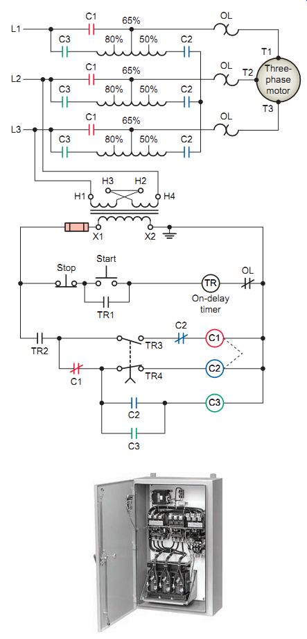
Ill. 16 Autotransformer starter.
WYE-DELTA STARTING
Wye-delta starting (also referred to as star-delta starting) involves connecting the motor windings first in wye during the starting period and then in delta after the motor has begun to accelerate. Wye-delta starters can be used with three-phase AC motors where all six leads of the stator windings are available (on some motors only three leads are accessible). Connected in a wye configuration, the motor starts with a significantly lower inrush current than if the motor windings had been connected in a delta configuration. Typical applications include central air conditioning equipment, compressors, and conveyors.
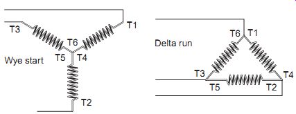
Ill. 17 Wye and delta motor winding connections.
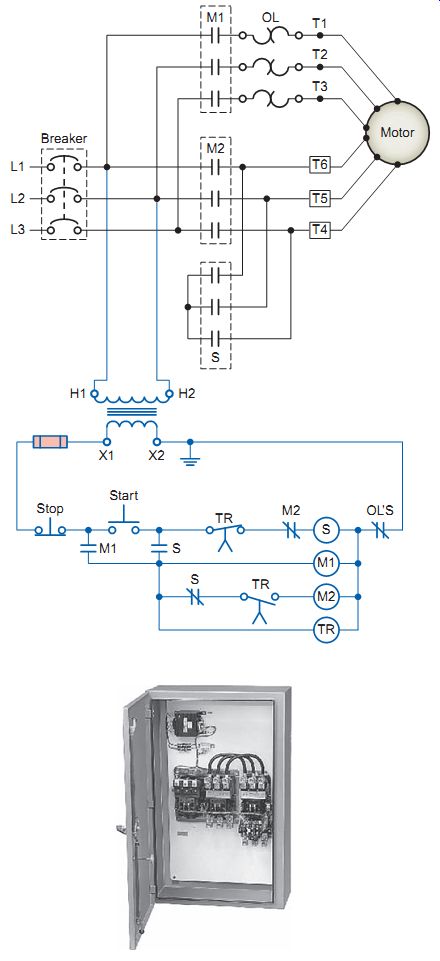
Ill. 18 Wye-delta starter.
Ill. 18 shows a typical wye-delta starting circuit.
Transition from wye to delta is made using three contactors and a timer. The two contactors that are closed during run are often referred to as the main contactor (M1) and the delta contactor (M2). The third contactor (S) is the wye contactor and that carries wye current only while the motor is connected in wye. Operation of the circuit can be summarized as follows:
• When the start push button is pressed, contactor S coil is energized.
• The S main power contacts close to connect the motor windings in a wye (or star) configuration.
• The normally open S auxiliary contact closes to energize timer coil TR and contactor coil M1
• The M1 main power contacts close to apply voltage to the wye-connected motor windings.
• Normally open auxiliary contacts S and M1 close to seal in and maintain timer coil S.
• After the time delay period has elapsed, the TR contacts change state to deenergize contactor coil S and energize contactor coil M2.
• S main power contacts, which hold the motor windings in a wye arrangement, open.
• The M2 contacts close and cause the motor windings to be connected in a delta configuration. The motor then continues to run with the motor connected in a delta arrangement.
• In most wye-delta starters, contactors S and M2 are electrically and mechanically interlocked. If both contactors were to be energized at the same time, the result would be a line-to-line short.
• With this type of "open transition" starter there is a very short period of time where no voltage is applied to the motor during transition from wye to delta connections. This condition can cause current surges or disturbances to be fed back into the main power source. The magnitude of the surges is proportional to the phase difference between the voltage generated by the running motor and the power source. These transients can in some instances affect other equipment that's sensitive to current surges.
PART-WINDING STARTING
Part-winding reduced-voltage starters are used on squirrel cage motors wound for dual-voltage operation, such as a 230/460-V motor. Power is applied to part of the motor windings on start-up and then is connected to the remaining coils for normal speed. These motors have two sets of windings connected in parallel for low-voltage operation and connected in series for high-voltage operation. When used on the lower voltage, they can be started by first energizing only one winding, limiting starting current and torque to approximately one-half of the full-voltage values. The second winding is then connected in parallel, once the motor nears operating speed. Since one set of windings has higher impedance (AC resistance) than the two connected in parallel, less inrush current flows to the motor on start-up. By strict definition, part-winding starting isn’t true reduced voltage starting since full voltage is applied to the motor at all times through acceleration and up to normal speed. The motor must be operated at the lower voltage, as the higher voltage would quickly damage the motor.
Part-winding starters are the least expensive type of reduced-voltage starters and use a simplified control circuit. However, they require a special motor design, and don’t have adjustments for current or torque. This starting method may not be suited for heavy-load applications because of the reduction of starting torque. Typical applications include low-inertia fans and blowers, low-inertia pumps, refrigeration, and compressors.
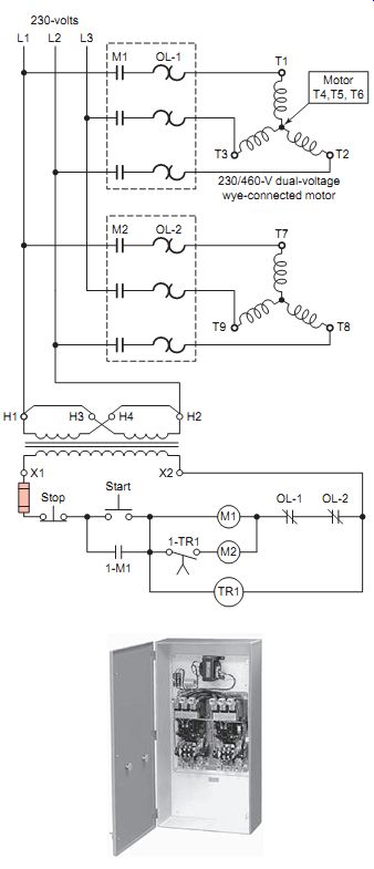
Ill. 19 Typical part-winding starting circuit.
Ill. 19 shows a typical part-winding starting circuit.
Operation of the circuit can be summarized as follows:
• In most cases the starter operates a 230/460-V dual voltage wye-connected motor operating at 230V.
• When the start push button is pressed, motor starter coil M1 and on-delay timer coil TR1 are energized.
• Auxiliary memory contact 1M-1 closes to seal in and maintain M1 and TR1 coils.
• The three M1 main contacts close, starting the motor at reduced current and torque through one half the wye windings.
• After a preset time delay, timed contact 1-TR1 closes and energizes starter coil M2.
• The three M2 main contacts close, applying voltage to the second set of wye windings.
• Both windings of the motor are now connected in parallel to the supply voltage for full current and torque.
• Once the motor is in normal operation, the motor full-load current (FLC) is divided between the two sets of windings and starters. The overload device must be sized to the winding it serves.
• It’s of utmost importance to connect the motor terminals (T1, T2, T3, T7, T8, and T9) to the proper terminals on the motor starter. The motor winding, T1-T2-T3, must be treated as a three-phase motor that when connected will have a definite direction of rotation. When motor winding T7-T8-T9 is connected, it must produce the same rotation. If by chance an error has been made, and T8 and T9 were interchanged, the second winding will attempt to change the rotation of the motor. Extremely high current will then flow, damaging the equipment.
OPEN and CLOSED TRANSITION FROM START TO RUN
Electromechanical reduced-voltage starters must make a transition from reduced voltage to full voltage at some point in the starting cycle. At this point there is normally a line current surge. The amount of surge depends on the type of transition used and the speed of the motor at the transition point.
Ill. 20 illustrates typical transition current curves for reduced-voltage starters. There are two methods of transition from reduced voltage to full voltage, namely, open-circuit transition and closed-circuit transition. Open transition means that the motor is actually disconnected from the line for a brief period of time when the transition takes place.
With closed transition, the motor remains connected to the line during transition. Open transition will produce a higher surge of current because the motor is momentarily disconnected from the line. Closed transition is preferred over open transition because it causes less electrical disturbance. The switching, however, is more expensive and complex.
(a) Open-circuit transition versus closed-circuit transition (b) Transition at low speed versus transition near full speed
% speed % speed Open transition Closed transition
% full-load current
% speed 600; % full-load current
% speed Transition near full speed Transition at low speed
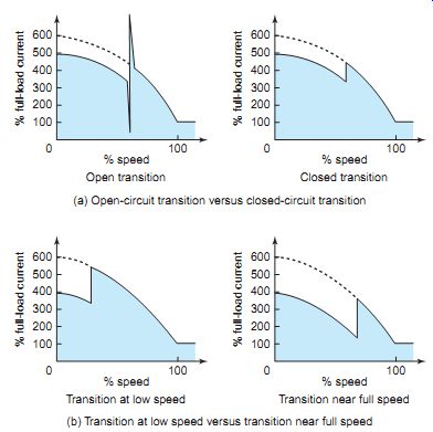
Ill. 20 Transition from reduced voltage to full voltage.
% full-load current; Run; % voltage Time (seconds) Ramped-up voltage Adjustable 2 to 30 s -- % speed -- Current limiting
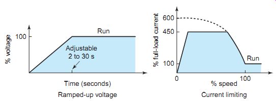
Ill. 21 Soft start
ramped-up voltage and current limiting.
SOFT STARTING
Electronic solid-state soft starters limit motor starting current and torque by ramping (gradually increasing) the voltage applied to the motor during the selected starting time. They are commonly used in operations requiring smooth starting and stopping of motors and driven machinery. Ill. 21 illustrates typical transition voltage and current curves for soft starters. The time to full voltage can be adjustable, usually from 2 to 30 seconds. As a result there is no large current surge when the controller is set up and correctly matched to the load. Current limiting is used when it’s necessary to limit the maximum starting current and is usually adjustable from 200 to 400 percent of full-load amperes.
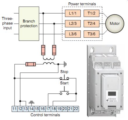
Ill. 22 Typical soft start starter. Control terminals: Three-phase input; Branch
protection
Ill. 22 shows the wiring for a typical soft start starter. The different standard modes of operation for this controller are:
Soft start
This method covers the most general applications. The motor is given an initial torque setting, which is user-adjustable. From the initial torque level, the output voltage to the motor is steplessly increased during the acceleration ramp time, which is user adjustable.
Selectable kick start
The kick start feature pro vides a boost at start-up to break away loads that may require a pulse of high torque to get started. It’s intended to provide a current pulse, for a selected period of time.
Current limit start
This method provides current limit start and is used when it’s necessary to limit the maximum starting current. The starting current is user-adjustable. The current limit starting time is user-adjustable.
Dual-ramp start
This starting method is useful on applications with varying loads, starting torque, and start time requirements. Dual-ramp start offers the user the ability to select between two separate start profiles with separately adjustable ramp times and initial torque settings.
Full-voltage his method is used in applications requiring across-the-line starting. The controller performs like a solid-state contactor. Full inrush cur rent and locked-rotor torque are realized. This controller may be programmed to provide full-voltage start in which the output voltage to the motor reaches full voltage in ¼ second.
Linear speed acceleration
With this type of acceleration mode, a closed-loop feedback system maintains the motor acceleration at a constant rate.
The required feedback signal is provided by a DC tachometer coupled to the motor.
Preset slow speed
This method can be used on applications that require a slow speed for positioning material. The preset slow speed can be set for either low, 7 percent of base speed, or high, 15 percent of base speed.
Soft Stop
The soft stop option can be used in applications requiring an extended stop time. The voltage ramp-down time is adjustable from 0 to 120 seconds. The load will stop when the voltage drops to a point where the load torque is greater than the motor torque.
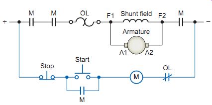
Ill. 23 Across-the-line DC motor starter.
DC Motor Starting
As was the case with AC motors, fractional horsepower manual starters or magnetic contactors and starters can be used for across-the-line starting of smaller DC motors. One major difference between AC and DC starters is the electrical and mechanical requirements necessary for suppressing the arcs created in opening and closing contacts under load. To combat prolonged arcing in DC circuits, the contactor switching mechanism is constructed so that the contacts will separate rapidly and with enough air gap to extinguish the arc as soon as possible on opening. Ill. 23 shows the schematic diagram for a typical DC across-the-line starter that uses three-wire control. To help extinguish the arc, the starter is equipped with three power contacts connected in series.
At the moment a DC motor is started, the armature is stationary and there is no counter emf being generated.
The only component to limit starting current is the armature resistance, which in most DC motors is a very low value. Common types of reduced-voltage DC starters include definite-time acceleration, current acceleration, counter-emf acceleration, and variable-voltage acceleration. Ill. 24 illustrates a two-stage DC definite-time resistance starter. When the power contact M closes, full line voltage is applied to the shunt field while the resistor is connected in series with the armature. After a preset time period, the contactor R closes, bypassing the resistor, allowing the motor to operate at base speed. This gives the motor smooth torque without creating a large surge of current. Operation of the circuit can be summarized as follows:
• Pressing the start button energizes the M and TR coils.
• Auxiliary memory contact M closes to seal in and maintain M and TR coils.
• The M main contact closes, starting the motor at reduced current and torque with the resistor connected in series with the armature.
• After a preset time delay, timed contact TR closes to energize contactor R coil.
• Contact R closes, bypassing the resistor and allowing full line voltage to be applied to the armature.
• The starting method is closed transition.
• Starting resistance can be shorted out in one or more steps, depending on motor size and the smoothness of acceleration desired.
• The shunt field has full line voltage applied to it any time the motor is on.
Ill. 25 illustrates variable-voltage acceleration of a DC shunt motor using a silicon controlled rectifier (SCR) armature voltage controller. The SCR provides a useful method of converting AC voltage to variable DC voltage.
An SCR is a semiconductor device that has three elements: anode, cathode, and gate. By applying a signal to the gate element at precisely the right time, you can control how much current the SCR will either pass or block during a cycle. This is known as phase control. The shorter the on time, the lower the DC voltage applied to the armature.
The shunt field is fed from a separate DC source and has full voltage applied any time the motor is on.
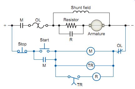
Ill. 24 Definite-time reduced-voltage DC starter.
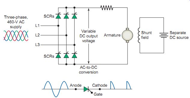
Ill. 25 Variable-voltage acceleration of a DC shunt motor.
QUIZ
1. Why is there initially a high inrush of current while a motor is being started?
2. How do the motor starting current value and the normal full-load current compare?
3. What will create a locked-rotor condition in a motor?
4. How is a full-voltage starter designed to start a motor?
5. Compare the way main contacts of a manual and magnetic starter are operated.
6. Explain the term no-voltage release as it applies to manual starters.
7. A magnetic across-the-line starter is operated by a single start/stop pushbutton station. If a second start/stop pushbutton station is added, how would the additional push buttons be connected relative to the existing ones?
8. What exactly is a combination motor starter?
9. State two reasons for the use of reduced-voltage starting.
10. Outline the operation of a primary-resistance induction motor starter.
11. Outline the operation of an autotransformer induction motor starter.
12. Outline the operation of a wye-delta induction motor starter.
13. Outline the operation of a part-winding induction motor starter.
14. Which type of reduced-voltage transition results in the least amount of electrical disturbance?
15. Explain the term ramping as it applies to soft starting of a motor.
16. Outline the operation of a definite-time reduced voltage DC starter.
17. Explain the term phase control as it applies to an SCR armature voltage controller.
Cont. to part c