AMAZON multi-meters discounts AMAZON oscilloscope discounts
Cont. from part b
Motor Reversing and Jogging
Reversing of AC Induction Motors
REVERSING THREE-PHASE INDUCTION MOTOR STARTER
Certain applications require a motor to operate in either direction. Interchanging any two leads to a three-phase induction motor will cause it to run in the reverse direction.
The industry standard is to interchange phase A (line 1) and phase C (line 3), while phase B (line 2) remains the same. Reversing starters are used to automatically accomplish this phase reversal.
The power circuit of a magnetic full-voltage three phase reversing motor starter is shown in Ill. 26.
This starter is constructed using two 3-pole contactors with a single overload relay assembly. The contactor on the left is usually designated as the forward contactor and the right contactor is usually designated as the reverse contactor. The power circuit of the two contactors is interconnected using bus bars or jumper wires. Power contacts (F) of the forward contactor, when closed, connect L1, L2, and L3 to motor terminals T1, T2, and T3, respectively. Power contacts (R) of the reverse contactor, when closed, connect L1 to motor terminal T3 and connect L3 to motor terminal T1, causing the motor to run in the opposite direction. Whether operating through either the forward or reverse contactor, the power connections are run through the same set of overload relays. Only one over load relay assembly is required, since the motor windings must be protected for the same current level regardless of the direction of rotation.
When the motor is reversed, it’s vital that both contactors not be energized at the same time. Activating both contactors would cause a short circuit, since two of the line conductors are reversed on one contactor. Both mechanical and electrical interlocks are used to prevent the forward and reverse contactors from being activated at the same time.
Mechanical interlocking is normally factory-installed and uses a system of levers to prevent both contactors from being engaged at the same time. The broken line indicates that the coils F and R cannot close contacts simultaneously because of the mechanical interlocking action of the device. E.g., energizing the coil of the forward contactor moves a lever in such a way as to physically block the movement of the reverse contactor. Even if the reverse contactor coil should become energized, the contacts won’t close because the mechanical interlock is physically blocking the reverse contactor.
The forward contactor coil must be deenergized before the reverse contactor can operate. The same scenario applies if the reverse contactor is energized. Mechanical interlocks have been known to fail and for this reason additional electrical interlocking is used for added protection.
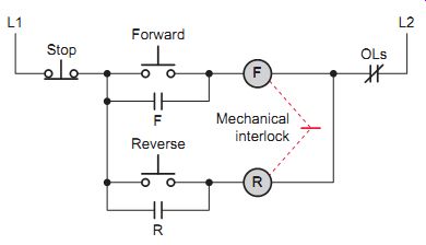
Ill. 27 Mechanical interlocking of forward and reverse contactors.
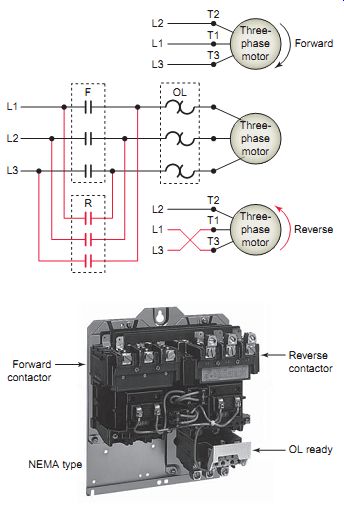
Ill. 26 Magnetic full-voltage three-phase reversing motor starter. Forward
contactor; Reverse contactor; OL ready; NEMA type
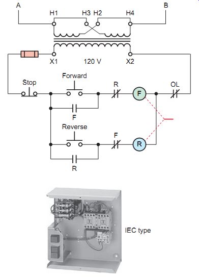
Ill. 28 Magnetic reversing starter with electrical interlock in the motor
starter.
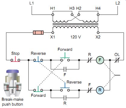
Ill. 29 Pushbutton interlocking.
Ill. 30 Limit switches incorporated into a reversing starter circuit
to limit travel.
Most reversing starters utilize auxiliary contacts operated by the forward and reverse coils to provide electrical inter locking. When the coil is energized, the frame of the contactor moves and activates the auxiliary contacts mounted on the contactor. The auxiliary contacts are connected to the motor control circuit and the state of the contacts (normally open or closed) is associated with coil of the contactor.
The control circuit illustrates how auxiliary contact interlocking works and can be summarized as follows:
• The normally closed contact controlled by the forward coil is connected in series with the reverse coil.
• The normally closed contact controlled by the reverse coil is connected in series with the forward coil.
• When the forward coil is energized, the normally closed contact in series with the reverse coil is opened to prevent the reverse coil from being energized.
• When the reverse coil is energized, the normally closed contact in series with the forward coil opens to prevent the forward coil from being energized.
• To reverse the motor with this control circuit, the operator must press the stop button to deenergize the respective coil, reclosing the respective normally closed contact.
• Reversing starters are usually factory-wired for electrical interlocking.
• Starter mechanical and electrical interlocking offers sufficient protection for most reversing motor control circuits.
Electrical pushbutton interlocking utilizes break-make, normally closed and normally open switch contacts on the forward and reverse buttons. The control circuit illustrates how pushbutton interlocking works and can be summarized as follows:
• Interlocking is achieved by connecting the normally closed contact of the reverse button in series with the normally open contact of the forward push button.
• The normally closed contact of the reverse push button acts like another stop push button in the forward circuit.
• The normally open contact on the reverse push but ton is used as the start button for the reverse circuit.
• When the reverse button is pressed, its normally closed contact opens the circuit to the forward coil and at the same time its normally closed contact completes the circuit to the reverse coil.
• When the forward button is pressed, its normally closed contact opens the circuit to the reverse coil and at the same time its normally closed contact completes the circuit to the forward coil.
• The motor reverses direction immediately with out the stop button being pressed. Take care when reversing large motors, as the sudden jar of reversal can damage the equipment the motor is driving.
High inrush currents can cause damage to both the motor and the controller if the motor is reversed without allowing enough time for the speed of the motor to decrease.
• Pushbutton interlocking should be used in conjunction with both mechanical and auxiliary electrical interlocking and is intended to supplement these methods, not replace them.
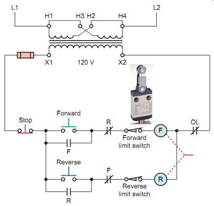
Limit switches can be used to limit the travel of electrically operated doors, conveyors, hoists, machine tool worktables, and similar devices. The control circuit illustrates how limit switches can be incorporated into a reversing starter circuit to limit travel. The operation of the circuit can be summarized as follows:
• Pressing the forward push button energizes coil F.
• Auxiliary memory contact F closes to seal in and maintain F coil.
• Auxiliary interlock contact F opens to isolate the reversing circuit.
• Power contacts F close and the motor runs in the forward direction.
• If either the stop button or forward limit switch is actuated, the holding circuit to coil F opens, deenergizing the coil and returning all F contacts to their normal deenergized state.
• Pressing the reverse push button energizes coil R.
• Auxiliary memory contact R closes to seal in and maintain R coil.
• Auxiliary interlock contact R opens to isolate the forward circuit.
• Power contacts R close and the motor runs in the reverse direction.
• If either the stop button or reverse limit switch is actuated, the holding circuit to coil R opens, deenergizing the coil and returning all R contacts to their normal deenergized state.
• The location of the limit switches in the circuit allows the one direction of travel to be stopped if the motor is driving a device that has limits to its travel. The opposite direction isn’t affected by one travel limit being opened. As soon as the motor is reversed and the actuator is no longer holding the limit switch open, it will return to its normally closed position.
Ill. 31 illustrates how a single-phase capacitor-start motor is wired to operate in the forward and reverse directions using a reversing starter. The direction of rotation is changed by interchanging the start winding leads, while those of the run winding remain the same. Unlike the three-phase motor, the single-phase capacitor-start motor must be allowed to slow down before any attempt to reverse the direction of rotation. The centrifugal switch in the start winding circuit opens at approximately 75 percent of the motor speed and must be allowed to reclose before the motor will reverse.
Certain machine tool operations require a repeated for ward and reverse action in their operation. Ill. 32 illustrates a reciprocating machine process that uses two limit switches to provide automatic control of the motor.
Each limit switch (LS1 and LS2) has two sets of contacts, one normally open and the other normally closed. The operation of the circuit can be summarized as follows:
• The start and stop push buttons are used to initiate and terminate the automatic control of the motor by limit switches.
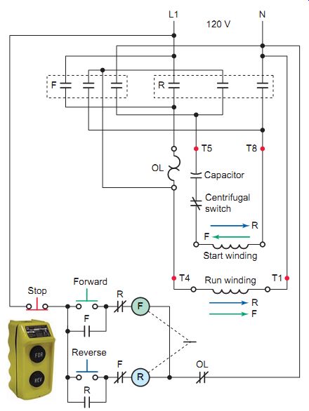
Ill. 31 Reversing a single-phase motor.
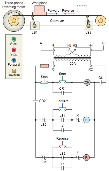
Ill. 32 Reciprocating machine process. Three-phase reversing motor;
• Contact CR1 is used to maintain the circuit to the control relay during the running operation of the circuit.
• Contact CR2 is used to make and break the line circuit to the forward and reverse control circuit.
• Using the control relay and its start and stop buttons also provides low-voltage protection-that is, the motor will stop when there is a supply voltage failure, and the motor won’t restart automatically when the supply voltage is restored.
• The normally closed contact of limit switch LS2 acts as the stop for the forward controller, and the normally open contact of limit switch LS1 acts as the start contact for the forward controller. The auxiliary contact of the forward starter is connected in parallel with the normally open contact of limit switch LS1 to maintain the circuit during the running of the motor in the forward direction.
• The normally closed contact of limit switch LS1 is wired as a stop contact for the reverse starter, and the normally open contact of limit switch LS2 is wired as a start contact for the reverse starter. The auxiliary contact on the reverse starter is wired in parallel with the normally open contacts of limit switch LS2 to maintain the circuit while the motor is running in reverse.
• Electrical interlocking is accomplished by the addition of a normally closed contact in series with each starter and operated by the starter for the opposite direction of rotation of the motor.
• Reversal of the direction of rotation of the motor is provided by the action of the limit switches. When limit switch LS1 is moved from its normal position, the normally open contact closes energizing coil F and the normally closed contact opens and drops out coil R. The reverse action is performed by limit switch LS2, and thus reversing in either direction is provided.
• The forward and reverse pushbuttons provide a means of starting the motor in either forward or reverse in order that the limit switches can take over automatic control.
Reversing of DC Motors
The reversal of a DC motor can be accomplished in two ways:
• Reversing the direction of the armature current and leaving the field current the same.
• Reversing the direction of the field current and leaving the armature current the same.
Most DC motors are reversed by switching the direction of current flow through the armature. The switching action generally takes place in the armature because the armature has a much lower inductance than the field. The lower inductance causes less arcing of the switching contacts when the motor reverses its direction.
Ill. 33 shows the power circuit for DC motor reversing using electromechanical and electronic control. For electromechanical operation, the forward contactor causes current to flow through the armature in one direction, and the reverse contactor causes current to flow through the armature in the opposite direction. For solid-state electronic control, two sets of SCRs are provided. One set is used for current flow in one direction through the armature, and the second set is used for current flow in the opposite direction.
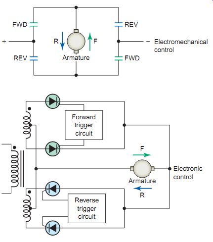
Ill. 33 DC motor reversing power circuits. Electromechanical control;
Electronic control; Forward trigger circuit
Jogging
Jogging (sometimes called inching) is the momentary operation of a motor for the purpose of accomplishing small movements of the driven machine. It involves an operation in which the motor runs when the push button is pressed and will stop when the push button is released.
Jogging is used for frequent starting and stopping of a motor for short periods of time.
The pushbutton jog circuit shown in Ill. 34 uses a standard start/stop control circuit with a double-contact jog push button: one normally closed contact and one normally open contact. The operation of the circuit can be summarized as follows:
• Pressing the start push button energizes starter coil M, causing the M main contacts to close to start the motor and the M auxiliary contact to close to maintain the M coil circuit.
• With the M coil deenergized and the jog push button then pressed, a circuit's completed for the M coil around the M auxiliary maintaining contact.
• The M main contacts close to start the motor, but the maintaining circuit's incomplete as the normally closed jog contact is open.
• As a result, starter coil M won’t seal in; instead, it can stay energized only as long as the jog button is fully depressed.
• On quick release of the jog push button, should its normally closed contacts reclose before the starter maintaining contact M opens, the motor would continue to run. In certain applications this could be hazardous to workers and machinery.
The control relay jogging circuit shown in Ill. 35 is much safer than the previous circuit. A single-contact jog push button is used; in addition, the circuit incorporates a jog control relay (CR). The operation of the circuit can be summarized as follows:
• Pressing the start push button completes a circuit for the CR coil, closing the CR1 and CR2 contacts.
• The CR1 contact completes the circuit for the M coil, starting the motor.
• The M maintaining contact closes; this maintains the circuit for the M coil.
• Pressing the jog button energizes the M coil only, starting the motor. Both CR contacts remain open, and the CR coil is deenergized. The M coil won’t remain energized when the jog push button is released.
Ill. 36 shows the use of a selector switch in the control circuit to obtain jogging. The start button doubles as a jog button. The operation of the circuit can be summarized as follows:
• When the selector switch is placed in the run position, the maintaining circuit'sn’t broken. If the start button is pressed, the M coil circuit's completed and maintained.
• Turning the selector switch to the jog position opens the maintaining circuit. Pressing the start button completes the circuit for the M coil, but the maintaining circuit's open. When the start button is released, the M coil is deenergized.
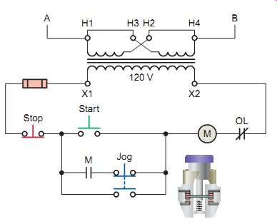
Ill. 34 Push button job circuit.
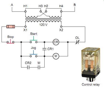
Ill. 35 Jog circuit with control relay.
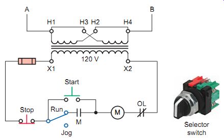
Ill. 36 Start/stop/selector jog control circuit.
QUIZ:
1. How can the direction of rotation of a three-phase induction motor be reversed?
2. An electromagnetic reversing motor starter is made up of what components?
3. What would occur if both contactors in a reversing motor starter were to become energized at the same time?
4. Explain the operation of the mechanical interlock in a reversing magnetic motor starter.
5. Explain how to provide electrical interlocking using auxiliary contacts.
6. What types of forward and reverse push buttons are utilized for pushbutton interlocking?
7. How is reversing a single-phase capacitor start motor accomplished using a magnetic motor starter?
8. Why are most DC motors reversed by switching the direction of current flow through the armature rather than the field?
9. What is a jog control used for?