AMAZON multi-meters discounts AMAZON oscilloscope discounts
Cont. from part c
Motor Stopping
The most common method of stopping a motor is to remove the supply voltage and allow the motor and load to coast to a stop. In some applications, however, the motor must be stopped more quickly or held in position by some sort of braking device. Electric braking uses the windings of the motor to produce a retarding torque. The kinetic energy of the rotor and the load is dissipated as heat in the rotor bars of the motor.
Plugging and Antiplugging
Plugging stops a polyphase motor quickly, by momentarily connecting the motor for reverse rotation while the motor is still running in the forward direction. This acts as a retarding force for rapid stop and quick reversal of motor rotation. Plugging produces more heat than most normal-duty applications. NEMA specifications call for starters used for such applications to be derated. That is, the next size larger reversing starter must be selected when it’s used for plugging to stop or reverse at a rate of more than five times per minute.
A zero-speed switch (also known as a plugging switch) wired into the control circuit of a standard reversing starter can be used for automatic plugging of a motor. A typical plugging switch is shown in Ill. 37. The switch is coupled to a moving shaft on the machinery whose motor is to be plugged. The zero-speed switch prevents the motor from reversing after it has come to a stop. As the zero-speed switch rotates, centrifugal force or a magnetic clutch causes its contacts to open or close, depending on the intended use. Each zero-speed switch has a rated operating speed range within which the contacts will be switched; E.g, 50 to 200 rpm.
The control schematic of Ill. 38 shows a typical control circuit for forward-direction plugging. The operation of the circuit can be summarized as follows:
• Pressing the start button closes and seals in the for ward contactor. As a result, the motor rotates in the forward direction.
• The normally closed auxiliary contact F opens the circuit to the reverse contactor coil.
• The forward contact on the speed switch closes.
• Pressing the stop button deenergizes the forward contactor.
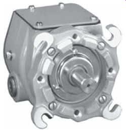
Ill. 37 Plugging switch.
• The reverse contactor is energized, and the motor is plugged.
• The motor speed decreases to the setting of the speed switch, at which point its forward contact opens and deenergizes the reverse contactor.
• This contactor is used only to stop the motor by using the plugging operation; it’s not used to run the motor in reverse.
The sudden reversing torque applied when a large motor is reversed (without slowing the motor speed) could damage the driven machinery, and the extremely high current could affect the distribution system. Antiplugging protection is obtained when a device prevents the application of a counter torque until the motor speed is reduced to an acceptable value.
The antiplugging circuit of Ill. 39 may be used to prevent reversing the motor before the motor has slowed to near zero speed. In this application the motor can be reversed but not plugged. The operation of the circuit can be summarized as follows:
• Pressing the forward button completes the circuit for the F coil, closing the F power contacts and causing the motor to run in the forward rotation.
• The F zero-speed switch contact opens because of the forward rotation of the motor.
• Pressing the stop button deenergizes the F coil, which opens the F power contacts, causing the motor to slow down.
• Pressing the reverse button won’t complete a circuit for the R coil until the F zero-speed switch contact recloses.
• As a result, when the rotating equipment reaches near zero speed, the reverse circuit may be energized, and the motor will run in the reverse rotation.
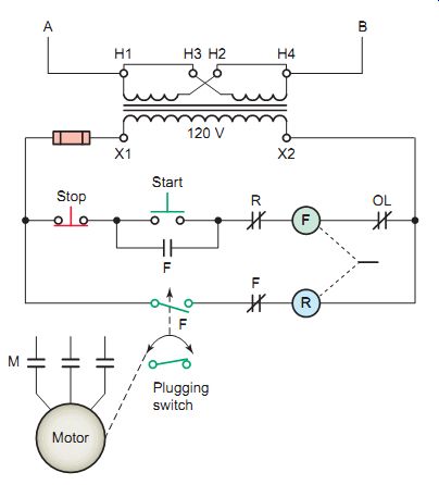
Ill. 38 Plugging a motor to stop it. Plugging switch
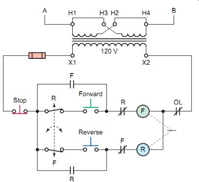
Ill. 39 Antiplugging protection circuit.
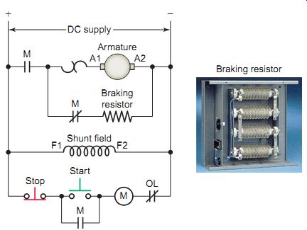
Ill. 40 Dynamic braking applied to a DC motor. Braking resistor
Ill. 41 DC injection braking applied to an AC induction motor.
Dynamic Braking
Dynamic braking is achieved by reconnecting a running motor to act as a generator immediately after it’s turned off, rapidly stopping the motor. The generator action converts the mechanical energy of rotation to electrical energy that can be dissipated as heat in a resistor. Dynamic braking of a DC motor may be needed because DC motors are often used for lifting and moving heavy loads that may be difficult to stop.
The circuit shown in Ill. 40 illustrates how dynamic braking is applied to a DC motor. The operation of the circuit can be summarized as follows:
• Assume the motor is operating and the stop button is pressed.
• Starter coil M deenergizes to open the normally open M power contact to the motor armature.
• At the same time, the normally closed M power contact closes to complete a braking circuit around the armature through the braking resistor, which acts like a load.
• The shunt field winding of the DC motor remains connected to the power supply.
• The armature generates a counter-emf voltage. This counter emf causes current to flow through the resistor and armature. The smaller the ohmic value of the braking resistor, the greater the rate at which energy is dissipated and the faster the motor comes to rest.
DC Injection Braking
DC injection braking is a method of braking in which direct current is applied to the stationary windings of an AC motor after the applied AC voltage is removed. The injected DC voltage creates a magnetic field in the motor stator winding that doesn’t change in polarity. In turn, this constant magnetic field in the stator creates a magnetic field in the rotor. Because the magnetic field of the stator isn’t changing in polarity, it will attempt to stop the rotor when the magnetic fields are aligned (N to S and S to N).
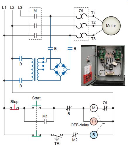
The circuit of Ill. 41 is one example of how DC injection braking can be applied to a three-phase AC induction motor. The operation of the circuit can be summarized as follows:
• The DC injection voltage is obtained from the full wave bridge rectifier circuit, which changes the line voltage from AC to DC.
• Pressing the start button energizes starter coil M and off-delay timer coil TR.
• Normally open M1 auxiliary contact closes to maintain current to the starter coil and normally closed M2 auxiliary contact opens to open the current path to braking coil B.
• Normally open off-delay timer contact TR remains closed at all times while the motor is operating.
• When the stop button is pressed, starter coil M and off-delay timer coil TR are deenergized.
• Braking coil B becomes energized through the closed TR contact.
• All B contacts close to apply DC braking power to two phases of the motor stator winding.
• Coil B is deenergized after the timer contact time out. The timing contact is adjusted to remain closed until the motor comes to a complete stop.
• A transformer with tapped windings is used in this circuit to adjust the amount of braking torque applied to the motor.
• The motor starter (M) and braking contactor (B) are mechanically and electrically interlocked so that the AC and DC supplies are not connected to the motor at the same time.
Electromechanical Friction Brakes
Unlike plugging or dynamic braking, electromechanical friction brakes can hold the motor shaft stationary after the motor has stopped. Ill. 42 shows an electromechanical drum and shoe-type friction brake used on DC series motor drives. The brake drum is attached to the motor shaft and the brake shoes are used to hold the drum in place. The brake is set with a spring and released by a solenoid. When the motor is running, the solenoid is energized to overcome the tension of the spring, thus keeping the brake shoes clear of the drum.
When the motor is turned off, the solenoid is deenergized and the brake shoes are applied to the drum through the spring tension. The brake operating coil is connected in series with the motor armature and release and sets in response to motor current. This type of braking is fail-safe in that the brake is applied in case of an electrical failure.
AC motor brakes are commonly used as parking brakes to hold a load in place or as stopping brakes to decelerate a load. Applications include material handling, food processing, and baggage handling equipment. These motors are directly coupled to an AC electromagnetic brake, as shown in Ill. 43. When the power source is turned off, the motor stops instantaneously and holds the load.
Most come equipped with an external manual release device, which allows the driven load to be moved without energizing the motor.
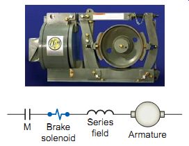
Ill. 42 Electromechanical drum and shoe-type friction brake used on DC
series motor drives. Armature; Series field -- Brake solenoid
QUIZ:
1. How is plugging used to stop a motor?
2. Explain how a zero-speed switch functions in antiplugging.
3. What type of starter is required for forward plugging of a motor?
4. How is dynamic braking used to stop a motor?
5. How is DC injection braking used to stop a motor?
6. How is an electromechanical friction brake set and released?