AMAZON multi-meters discounts AMAZON oscilloscope discounts
Cont. from part d
Motor Speed
Multispeed Motors
The speed of an induction motor depends on the number of poles built into the motor and the frequency of the electrical power supply. A single-speed motor has one rated speed at which it runs when supplied with the nameplate voltage and frequency. A multispeed motor will run at more than one speed, depending on how you connect it to the supply. Multispeed motors typically have two speeds to choose from, but may have more.
The different speeds of a multispeed motor are selected by connecting the external motor winding stator leads to a multispeed starter. One starter is required for each speed of the motor and each starter must be interlocked to prevent more than one starter from being on at the same time. Multispeed motors are available in two basic versions: consequent pole and separate winding. A separate winding motor has a winding for each speed while a con sequent pole motor has a winding for every two speeds.
The starter for a consequent-pole two-speed motor requires a three-pole unit and a five-pole unit. Starters for separate-winding two-speed motors consist of two standard three-pole starter units that are electrically and mechanically interlocked and mounted in a single enclosure. Ill. 44 shows a factory-wired two-speed separate winding IEC starter. A variety of factory and field-installed wiring configurations are used. The makeup of the starter is as follows:
- • A high-speed and a low-speed starter, mechanically and electrically interlocked with each other.
- • Two sets of overload relays, one for the high-speed circuit and one for the low-speed circuit to ensure adequate protection on each speed range.
- • A hinged control panel containing high-speed push button, low-speed push button, off/high/low selector switch, high-speed OL reset, and low-speed OL reset.
In most instances, the three-phase, two-speed, six-lead squirrel-cage induction motor is a common application of a multispeed motor. A typical example would be a four pole machine (with synchronous speed of 1,800 rpm) connected to operate at 1,800 rpm (high) and 900 rpm (low). It’s important to carefully connect the motor leads to the starter as shown on the motor nameplate or on the connection diagram. Be sure to test each speed connection separately for direction of rotation before connecting the mechanical load.
The NEC requires that you protect each winding or connection against overloads and shorts. To meet this requirement you must:
- • Use separate overloads for each winding.
- • Size the branch-circuit conductors that supply each winding for the full-load current (FLC) of the highest FLC winding.
- • Ensure the controller horsepower rating isn't less than that required for the winding with the highest horsepower rating.
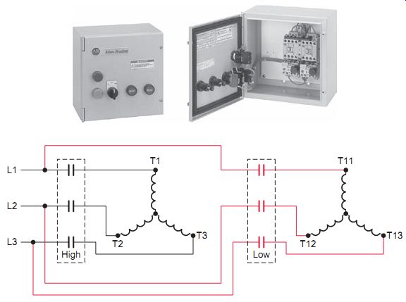
Ill. 44 Two-speed separate winding across-the-line motor starter.
Wound-Rotor Motors
Construction of wound-rotor motors is different from that of squirrel-cage motors, basically in the design of the rotor. The wound rotor is constructed with windings that are brought out of the motor through slip rings on the motor shaft. These windings are connected to a controller, which places variable resistors in series with the windings. By changing the amount of external resistance connected to the rotor circuit, the motor speed can be varied (the lower the resistance, the higher the speed). Wound-rotor motors are most common in the range of 300 hp and above in applications where using a squirrel-cage motor may result in a starting current that's too high for the capacity of the power system.
Ill. 45 shows the power circuit for a wound-rotor magnetic motor controller. It consists of a magnetic starter (M), which connects the primary circuit to the line, and two secondary accelerating contactors (S and H), which control the speed. The operation of the circuit can be summarized as follows:
- • When operating at low speed, contactors S and H are both open, and full resistance is inserted in the rotor's secondary circuit.
- • When contactor S closes, it shunts out part of the total resistance in the rotor circuit; as a result, the speed increases.
- • When contactor H closes, all resistance in the secondary circuit of the motor is bypassed; thus, the motor runs at maximum speed.
One disadvantage of using resistance to control the speed of a wound-rotor induction motor is that a lot of heat is dissipated in the resistors; the efficiency, there fore, is low. Also, speed regulation is poor; for a given amount of resistance, the speed varies considerably if the mechanical load varies. Modern wound-rotor controllers use solid-state devices to obtain stepless control. These may incorporate thyristors (semiconductors) that serve in the place of magnetic contactors.
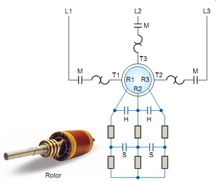
Ill. 45 Wound-rotor magnetic motor controller.
QUIZ
1. How are the different speeds of a multispeed motor determined?
2. Compare the number of poles required for the starters of a consequent-pole and a separate-winding three-phase two-speed motor.
3. According to the NEC, what current rating must be used when calculating the size of the branch-circuit conductors for a multispeed motor installation?
4. In what way is the construction of wound-rotor motors different from that of squirrel-cage motors?
5. Explain the relationship between the speed and resistance of the external resistors of a wound-rotor induction motor.
REPAIR/TROUBLESHOOTING SCENARIOS:
1. What problems may be encountered when fuses or circuit breakers are sized too small for a specific application?
2. What might be the consequence if a DC starter is replaced by an AC starter with similar main contact voltage and current ratings?
3. In what way can excessive jogging have a negative effect on the operation of the starter and motor?
4. Why is it important to test each multispeed motor connection separately for direction of rotation before connecting the mechanical load?
FURTHER DISCUSSION TOPICS:
1. Determine each of the following for a 10-hp, three phase, 208-V motor with a service factor of 1.15.
a. Motor full-load current (FLC).
b. Size of THWN CU branch-circuit conductors required.
c. Fuse size (dual-element) to be used as motor branch circuit short-circuit and ground fault protection.
d. Current rating required for the motor disconnect switch.
e. Current rating for the overload relay located in the motor controller.
2. Explain why fuses and circuit breakers cannot be used to protect against overloads.
3. Why should stop push buttons be of the normally closed type?
4. Why must the AC and DC supplies of a DC injection braking circuit not be connected to the motor at the same time?