AMAZON multi-meters discounts AMAZON oscilloscope discounts
Cont. from part c
Integrated Circuits (ICs)
Fabrication
An integrated circuit (IC), sometimes called a chip, is a semiconductor wafer on which thousands or millions of tiny resistors, capacitors, and transistors are fabricated.
IC chips provide a complete circuit function in one small semiconductor package with input and output pin connections, as illustrated in Ill. 37. Most integrated circuits provide the same functionality as "discrete" semiconductor circuits at higher levels of reliability and at a fraction of the cost. Usually, discrete-component circuit construction is favored only when voltage and power dissipation levels are too high for integrated circuits to handle.
Integrated circuits may be categorized as either digital or analog, depending on their intended application. Digital ICs operate with on/off switch-type signals that have only two different states, called low (logic 0) and high (logic 1). Analog ICs contain amplifying-type circuitry and signals capable of an unlimited number of states.
The analog and digital processes can be seen in a simple comparison between a light dimmer and light switch.
A light dimmer involves an analog process, which varies the intensity of light from off to fully on. The operation of a standard light switch, on the other hand, involves a digital process; the switch can be operated only to turn the light off or on.
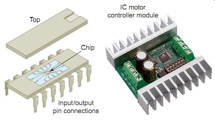
Ill. 37 Integrated circuit (IC). IC motor controller module; Top; Chip;
Input/output pin connections
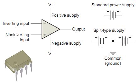
Ill. 38 Operational amplifier (op-amp). Standard power supply; Output;
Negative supply; Positive supply; Inverting input; Noninverting input
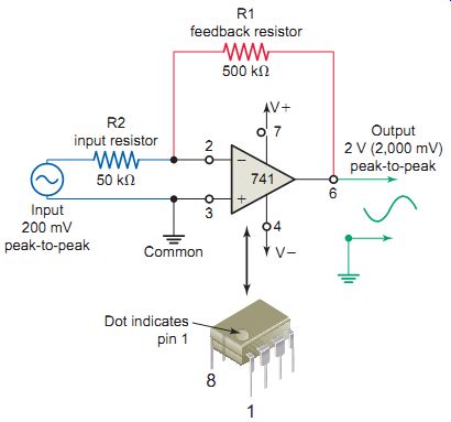
Ill. 39, 741 op-amp voltage amplifier circuit.
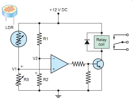
Ill. 40 Operational amplifier circuit con figured as a voltage comparator.
Operational Amplifier ICs
Operational amplifier ICs (often called op-amps) take the place of amplifiers that formerly required many discrete components. These amplifiers are often used in con junction with signals from sensors connected in control circuits. An op-amp is basically a high-gain amplifier that can be used to amplify low level AC or DC signals. The schematic symbol for an op-amp is a triangle, shown in Ill. 38. The triangle symbolizes direction and points from input to output. The connections associated with an op-amp can be summarized as follows:
• The op-amp has two inputs and a single output. The inverting input (-) produces an output that is 180° out of phase with the input. The second input, called the noninverting input (+), produces an output that is in phase with the input.
• The DC power supply terminals are identified as +V and -V. All op-amps need some type of power supply, but some diagrams won’t show the power supply terminals, as it’s assumed that they are always there. The supply power will be determined by the type of output the op-amp is required to produce. E.g., if the output signal needs to produce both positive and negative voltages, then the power supply will need to be a split, or differential, type with both positive and negative voltages and a common ground. If the op-amp needs to produce only positive voltages, then the power supply be the standard, or traditional, DC type.
The op-amp is connected in a number of ways to perform different functions. Ill. 39 shows the schematic diagram of a 741 op-amp circuit con figured as an AC inverting amplifier . A split-type power sup ply, consisting of a positive supply and an equal and opposite negative supply, is used to operate the circuit. The operation of the circuit can be summarized as follows:
• Two resistors, R1 and R2, set the value of the volt age gain of the amplifier.
• Resistor R2 is called the input resistor and resistor R1 is called the feedback resistor.
• The ratio of the resistance value of R2 to that of R1 sets the voltage gain of the amplifier.
• The op-amp amplifies the AC input voltage it receives and inverts its polarity.
• The output signal is 180° out of phase with the input signal.
• The op-amp gain for the circuit is calculated as follows:
Op-amp gain = R1 / R2
Ill. 40 shows the schematic diagram of an operational amplifier circuit con figured as a differential amplifier or voltage comparator with its output signal being the difference between the two input signals or voltages, V2 and V1. A light-dependent resistor (LDR) is used to sense the light level. When LDR is not illuminated, its resistance is very high, but once illuminated with light, its resistance drops dramatically. The circuit is operated with a standard DC power supply and without a feedback circuit. The operation of the circuit can be summarized as follows:
• The resistor combination R1 and R2 form a fixed reference voltage input V2, set by the ratio of the two resistors.
• The resistor combination LDR and R3 form the variable voltage input V1.
• When the light level sensed by the LDR drops and the variable output voltage V1 falls below the reference voltage at V2, the output from the op-amp changes, activating the relay and switching the connected load.
• Likewise, as the light level increases the output will switch back, turning the relay off.
• The preset resistor R3 value can be adjusted up or down to increase or decrease resistance; in this way it can make the circuit more or less sensitive.
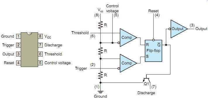
Ill. 41, The 555 IC timer. Ground, Trigger, Output Threshold, Discharge,
Reset Control voltage Vcc 8
555 Timer IC
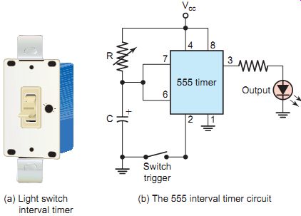
Ill. 42 A 555 IC interval timer. (a) Light switch interval timer; (b)
The 555 interval timer circuit; Switch trigger
The 555 timer IC is used as a timer in circuits requiring precision timing as well as an oscillator to provide pulses needed to operate digital circuits. Ill. 41 shows the pinout functional block diagram of the 555 chip. The internal circuitry of the chip is made up of a complex maze of transistors, diodes, and resistors.
The light switch interval timer shown in Ill. 42a is an ideal application for lights that are needlessly left on or forgotten. The dial is set for the amount of time the lights are to be left on, from 1 minute to 18 hours. Time intervals are initiated on the closure of the switch. After the preset time has elapsed the lights will go off automatically regardless of the state (open or closed) of the switch.
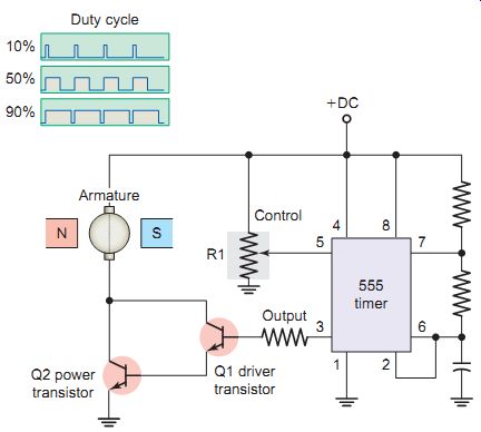
Ill. 43 The 555 CD motor speed controller.
Ill. 44 Microcontroller used in motor control applications.
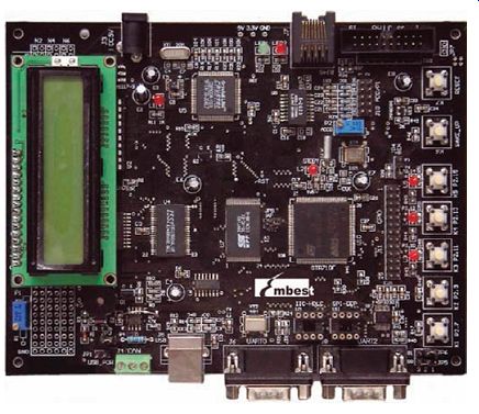
Ill. 45 Embedded microcontroller.
Ill. 42b shows a 555 timer version of an interval timer. The operation of the circuit can be summarized as follows:
• The time period is determined by the value of the two external timing components R and C.
• When the switch opens the external capacitor is held discharged (short-circuited) by a transistor inside the timer.
• When the switch is closed, it releases the short circuit across the capacitor and triggers the LED into conduction. At this point the timing period starts.
• Capacitor C starts to charge through resistor R.
• When the charge on the capacitor reaches two-thirds of the source voltage, the timing period ends and the LED is automatically switched off.
• At the same time the capacitor discharges to ready for the next triggering sequence.
A common method of DC motor speed control is pulse-width modulation (PWM). Pulse-width modulation is the process of switching the power to a device on and off at a given frequency, with varying on and off times.
This relation between on and off times is referred to as the duty cycle. Ill. 43 shows the 555 timer used as a pulse width modulator oscillator that controls the speed of a small permanent-magnet DC motor. While most DC motor drives use a microcontroller to generate the required PWM signals, the 555 PWM circuit shown will help you to understand how this type of motor control operates. The operation of the circuit can be summarized as follows:
• The voltage applied across the armature is the aver age value determined by the length of time that transistor Q2 is turned on compared to the length of time it’s turned off (duty cycle).
• Potentiometer R1 controls the length of time the output of the timer will be turned on, which in turn controls the speed of the motor.
• If the wiper of R1 is adjusted to a higher positive voltage, the output will be turned on for a longer period of time than it will be turned off.
Microcontroller
An electronic motor controller can include means for starting and stopping the motor, selecting forward or reverse rotation, selecting and regulating the speed, regulating or limiting the torque, and protecting against over loads and faults. As integrated circuitry evolved, all of the components needed for a controller were built right onto one microcontroller chip. A microcontroller (also called a digital-signal controller or DSC) is an ultra-large-scale integrated circuit that functions as a complete computer on a chip, containing a processor, memory, and input/ output functions.
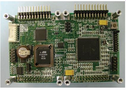
Ill. 44 shows a typical microcontroller IC that can be used in a variety control applications.
Microcontrollers are most often "embedded," or physically built into, the devices they control, as shown in Ill. 45. An embedded microcontroller is designed to do some specific task, rather than to be a general-purpose computer for multiple tasks. The software written for embedded systems is often called firmware, and is stored in read-only memory or flash memory chips rather than a disk drive. Microcontrollers often run with limited computer hardware resources: small or no keyboard and screen, and little memory.
The block diagram of Ill. 46 shows a micro controller used to control the operation of the inverter section of a variable-speed AC motor drive. The rotating speed of AC induction motors is determined by the frequency of the AC applied to the stator, not the applied voltage. However, stator voltage must also drop to prevent excessive current flow through the stator at low frequencies. The microcontroller controls the volt age and frequency and sets the proper stator voltage for any given input frequency. Two phase currents are measured and returned to the microcontroller along with rotor speed and angular-position information from the encoder/tachometer.
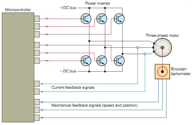
Ill. 46 Microcontroller used to control the operation of the inverter
section of a variable-speed AC motor drive. Current feedback signals;
Mechanical feedback signals (speed and position); Three-phase motor; Encoder/tachometer;
Power inverter; Microcontroller
Electrical Discharge (ESD)
Static charge is an unbalanced electrical charge at rest.
Typically, it’s created by insulator surfaces rubbing together or pulling apart. One surface gains electrons, while the other surface loses electrons. This results in an unbalanced electrical condition known as static charge.
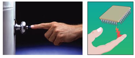
When a static charge moves from one surface to another, it becomes electrostatic discharge (ESD). Ill. 47 shows a common example of ESD. When a person (negatively charged) contacts a positively charged or a grounded object, electrons will move from one to the other. ESD, which is a bit annoying but certainly harmless to humans, can be lethal to sensitive electronic devices.
All integrated circuits are sensitive to electrostatic discharge to some degree. If static discharge occurs at a sufficient magnitude, some damage or degradation (the IC is weakened and will often fail later) will usually occur.
Damage is mainly due to the current flowing through ICs during discharge. Basically what happens is that a relatively large amount of heat is generated in a localized volume significantly faster than it can be removed, leading to a temperature in excess of the material's safe operating limits.
Ill. 47 Electrostatic discharge (ESD).

Ill. 48 Antistatic wrist strap band.
Ill. 48 shows an antistatic wrist strap band used to prevent a static charge from building up on the body by safely grounding a person working on sensitive electronic equipment. The wrist strap is connected to ground through a coiled retractable cable and resistor. An approved grounding wrist band has a resistance built into it, so it discharges static electricity but prevents a shock hazard when the wearer is working with lower circuit voltages.
Other precautions that should be taken when working on integrated circuits include:
• Never handle sensitive ICs by their leads.
• Keep your work area clean, especially of common plastics.
• Handle printed circuit boards by their outside corners.
• Always transport and store sensitive ICs and control boards in antistatic packaging.
Digital Logic
Logic circuits perform operations on digital signals. In digital or binary logic circuits there are only two values,
0 and 1. Logically, we can use these two numbers or we can specify that:
0 = false = no = off = open = low
1 = true = yes = on = closed = high
Using the binary two-value logic system, every condition must be either true or false; it cannot be partly true or partly false. While this approach may seem limited, it can be expanded to express very complex relationships and interactions among any number of individual conditions.
One reason for the popularity of digital logic circuits is that they provide stable electronic circuits that can switch back and forth between two clearly defined states, with no ambiguity attached. Integrated circuits are the least expensive way to make logic gates in large volumes. They are used in programmable controllers to solve complex logic.
Logic is the ability to make decisions when one or more different factors must be taken into account before an action is taken. Digital circuits are constructed from small electronic circuits called logic gates. The and gate is a logic circuit that has two or more inputs and a single output. Ill. 49 shows the traditional and IEC symbols used for a two-input and gate. The operation of the and gate is summarized by the table. Such a table, called a truth table, shows the output for each possible input. The basic logic that applies is that if all inputs are 1, the output will be 1. If any input is 0, the output will be 0.
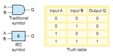
Ill. 49 Two-input and gate.
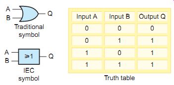
Ill. 50 Two-input OR gate.
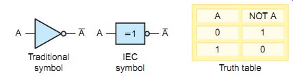
Ill. 51 The NOT function.
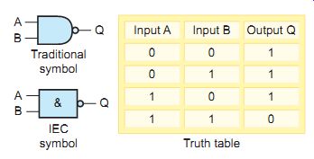
Ill. 52 Two-input NAND gate.
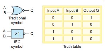
Ill. 53 Two-input NOR gate.
An OR gate produces a 1 output if any of its inputs are 1s. The output is 0 if all the inputs are 0s. An OR gate can have two or more inputs; its output is true if at least one input is true. Ill. 50 shows the traditional and IEC symbols used for a two-input OR gate along with its truth table.
The simplest logic circuit is the NOT circuit . It per forms the function called inversion, or complementation, and is commonly referred to as an inverter. The purpose of the inverter is to make the output state the opposite of the input state. Ill. 51 shows the traditional and IEC symbols used for a NOT function along with its truth table. Unlike the and / OR gate functions, the NOT function can have only one input. If a 1 is applied to the input of an inverter, a 0 appears on its output. The input to an inverter is labeled A and the output is labeled (read "NOT A"). The bar over the letter indicates the complement of A. Because the inverter has only one input, only two input combinations are possible.
A NAND gate is a combination of an inverter and an and gate. It’s called a NAND gate after the NOT-AND function it performs. Ill. 52 shows the traditional and IEC symbols used for a two-input NAND gate along with its truth table. The bubble on the output end of the symbol means to invert the and function. Notice that the output of the NAND gate is the complement of the output of an and gate. A NAND gate can have two or more inputs. Any 0 in the inputs yields a 1 output. The NAND gate is the most commonly used logic function. This is because it can be used to construct an and gate, OR gate, inverter, or any combination of these functions.
A NOR gate is a combination of an inverter and an OR gate. Its name is derived from its NOT-OR function.
Ill. 53 shows the traditional and IEC symbols used to represent a two-input NOR gate along with its truth table. The output of the NOR gate is the complement of the output of the OR-function output. The output Q is 1 if NOR inputs A or B are 1. A NOR gate can have two or more inputs and its output is 1 only if no inputs are 1.
The term hard-wired logic refers to logic control functions that are determined by the way devices are interconnected. Hard-wired logic is fixed in that it’s changeable only by changing the way the devices are connected. In contrast, programmable logic, such as that used in programmable logic controllers (PLCs), is based on basic logic functions, which are easily changed by modifying the program. PLCs use logic functions either singly or in combination to form instructions that will determine if a device is to be switched on or off.
Ill. 54 shows a hard-wired circuit and the equivalent PLC logic program for an and logic control function. Both normally open input limit switches (LS1 and LS2) must be closed to energize the output solenoid valve. This control logic is implemented in the hard-wired circuit by connecting the two limit switches and the solenoid valve all in series.
The PLC program uses the same inputs (LS1 and LS2) and output (SOL) devices connected to the PLC, but implements the logic via the program rather than the wiring.
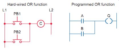
Ill. 55 Hard-wired circuit and the equivalent PLC logic program for an OR logic
control function. Hard-wired OR function; Programmed OR function
Ill. 55 shows a hard-wired circuit and the equivalent PLC logic program for an OR logic control function. Either one of the two normally open push buttons (PB1 or PB2) is closed to energize the contactor coil (C). This control logic is implemented in the hard-wired circuit by connecting the two input push buttons in parallel with each other to control the output coil. The PLC pro gram uses the same inputs (PB1 and PB2) and output (C) devices connected to the PLC, but implements the logic via the program rather than the wiring.
AND / OR logic use normally open input devices that must be closed to supply the signal that energizes the loads.
NOT logic energizes the load when the control signal is off.
Ill. 56 shows a hard-wired circuit and the equivalent PLC logic program for a NOT logic control function. This example is that of the NOT function used to control the interior lamp of a refrigerator. When the door is opened, the lamp automatically switches on. The switch controlling the lamp is a normally closed type that is held open by the shut door. When the door is opened, the switch returns to its normal closed state and the load (lamp) is energized.
For the load to remain energized there must not be a signal from the switch input. To keep the lamp on, the normally closed contact must not change its normally closed state.
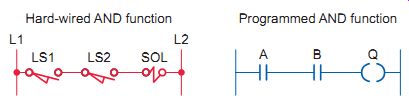
Ill. 54 Hard-wired circuit and the equivalent PLC logic program for
an and logic control function. Hard-wired and function; Programmed and
function
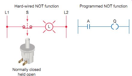
Ill. 56 Hard-wired circuit and the equivalent PLC logic program for
a NOT logic control function. Hard-wired NOT function; Programmed NOT
function; Normally closed held open
QUIZ:
1. Describe the makeup of an integrated circuit.
2. What advantages does an IC have over discrete component circuit construction?
3. What type of circuit is not suited to integrate onto a chip?
4. Compare the functioning of digital and analog integrated circuits.
5. What is an operational amplifier?
6. An operational amplifier is connected as a voltage amplifier. How is the gain of the circuit determined?
7. Explain the operation of an op-amp when con figured as a voltage comparator.
8. What are the two major applications for the 555 timer IC?
9. Give a brief explanation of how a 555 interval timer circuit works.
10. A 555 timer is con figured as a pulse-width modulator to vary the speed of a DC motor. How exactly does it operate to change the speed of the motor?
11. List some of the control tasks that a microcontroller designed for control of an electric motor may be required to perform.
12. What does the term embedded microcontroller refer to?
13. Explain the role of a microcontroller when used to control the inverter section of a variable-speed AC motor drive.
14. In what way can electrostatic discharge damage an integrated circuit?
15. List some of the precautions that should be taken when handling sensitive IC chips.
16. What can the terms logic 0 and logic 1 represent?
17. What makes digital circuitry so popular?
18. It’s desired to have a lamp turn on when one of three switches is closed. What control logic function would be used?
19. What control logic function energizes the load when the control signal is off?
20. What control logic function is used to implement five inputs connected in series with the requirement that all five must be closed to energize the load?
21. Compare the way in which hard-wired logic differs from programmable logic.
REPAIR/ TROUBLESHOOTING SCENARIOS:
1. One of the diodes of a single-phase full-wave rectifier is mistakenly connected backward in the bridge configuration. What effect will this have on the resultant DC output voltage and current flow through the diodes?
2. The insulation resistance of a motor operated by an electronic drive is to be tested using a megger. What precaution should you take? Why?
3. If the triac in the internal circuit of a lamp dimmer were to fail shorted, what effect would this most likely have on the operation of the circuit?
4. In what ways would the approach to trouble shooting for integrated circuits be different from that for a circuit constructed with discrete components?
MORE QUESTIONS:
1. What circuitry would have to be incorporated into an LED pilot light module rated to be operated directly by a 240-V AC source?
2. The best source to verify correct operation of modular electronic components is the operating manual. Why?
3. What are the advantages of using a triac rather than a rheostat for lamp dimming applications?