AMAZON multi-meters discounts AMAZON oscilloscope discounts
Cont. from part b
Thyristors
Thyristor is a generic term for a broad range of semiconductor components used as an electronic switch. Like a mechanical switch it has only two states: on (conducting) and off (not conducting). Thyristors have no linear in-between state as transistors have. In addition to switching, they can also be used to adjust the amount of power applied to a load.
Thyristors are mainly used where high currents and voltages are involved. They are often used to control alternating currents, where the change of polarity of the current causes the device to automatically switch off. The silicon-controlled rectifier and triac are the most frequently used thyristor devices.
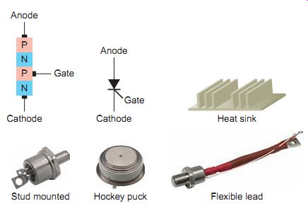
Ill. 27 Silicon-controlled rectifier (SCR). Stud mounted Hockey puck
Flexible lead; Heat sink;
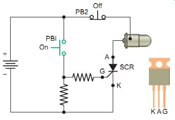
Ill. 28 SCR operated from a DC source. SCR; KAG
Silicon Controlled Rectifiers (SCRs)
Silicon controlled rectifiers (SCRs) are similar to silicon diodes except for a third terminal, or gate, which controls, or turns on, the SCR. Basically the SCR is a four-layer (PNPN) semiconductor device composed of an anode (A), cathode (K) and gate (G), as shown in Ill. 27. Common SCR case styles include stud-mounted, hockey puck, and flexible lead. SCRs function as switches to turn on or off small or large amounts of power. High-current SCRs that can handle load currents in the thousands of amperes have provisions for some type of heat sink to dissipate the heat generated by the device.
In function, the SCR has much in common with a diode.
Like the diode, it conducts current in only one direction when it’s forward-biased from anode to cathode. It’s unlike the diode because of the presence of a gate (G) lead, which is used to turn the device on. It requires a momentary positive voltage (forward-biased) applied to the gate to switch it on. When turned on it conducts like a diode for one polarity of current. If not triggered on, it won’t conduct a current regardless of whether it’s forward-biased.
The schematic of an SCR switching circuit that is operated from a DC source is shown in Ill. 28. The operation of the circuit can be summarized as follows:
• The anode is connected so that it’s positive with respect to the cathode (forward-biased).
• Momentarily closing push button PB1 applies a positive current-limited voltage to the gate of the SCR, which switches the anode-to-cathode circuit into conduction, thus turning the lamp on.
• Once the SCR is on, it stays on, even after the gate voltage is removed. The only way to turn the SCR off is to reduce the anode-cathode current to zero by removing the source voltage from the anode cathode circuit.
• Momentarily pressing push button PB2 opens the anode-to-cathode circuit to switch the lamp off.
• It’s important to note that the anode-to-cathode circuit will switch on in just one direction. This occurs only when it’s forward biased with the anode positive with respect to the cathode and a positive volt age is applied to the gate.
The problem of SCR turn-off does not occur in AC circuits. The SCR is automatically shut off during each cycle when the AC voltage across the SCR nears zero. As zero voltage is approached, anode current falls below the holding current value. The SCR stays off throughout the entire negative AC cycle because it’s reverse biased.
The schematic of an SCR switching circuit that is operated from an AC source is shown in Ill. 29. Because the SCR is a rectifier, it can conduct only one-half of the AC input wave. The maximum output delivered to the load, therefore, is 50 percent; its shape is that of a half wave pulsating DC waveform. The operation of the circuit can be summarized as follows:
• The anode-cathode circuit can be switched on only during the half-cycle when the anode is positive (forward-biased).
• With the push button open, no gate current flows, so the anode-cathode circuit remains off.
• Pressing the push button continuously closed causes the gate-cathode and anode-cathode circuits to be forward-biased at the same time. This produces a half wave pulsating direct current through the lamp load.
• When the push button is released, the anode-
cathode current is automatically shut off when the AC voltage drops to zero on the sine wave.
When the SCR is connected to an AC source, it can also be used to vary the amount of power delivered to a load by phase angle control. Ill. 30 shows the circuit of a single-phase fully controlled SCR bridge rectifier circuit.
The main purpose of this circuit is to supply a variable DC output voltage to the load. The operation of the circuit can be summarized as follows:
• A pulse trigger is applied to the gate at the instant that the SCR is required to turn on. This pulse is relatively short and would typically be applied to the gate via a pulse transformer.
• The circuit has two pairs of SCRs with SCR-1 and SCR-4 forming one pair and SCR-2 and SCR-3 the other pair.
• During the positive half of the AC input waveform, SCR-1 and SCR-4 can be triggered into conduction.
• During the negative half of the AC input waveform, SCR-2 and SCR-3 can be triggered into conduction.
• Power is regulated by advancing or delaying the point at which each pair of SCRs is turned on within each half-cycle.
• Even though the direction of current through the source alternates from one half-cycle to the other half-cycle, the current through the load remains in the same direction.
SCRs are often employed in solid-state reduced-voltage starters to reduce the amount of voltage delivered to an AC motor on starting. Ill. 31 shows a typical solid state reduced-voltage control circuit made up of two contactors: a start contactor and a run contactor. The SCR is a unidirectional device in that it can conduct current in one direction only. In this application bidirectional operation is obtained by connecting two SCRs in antiparallel (also known as reverse parallel). Using the antiparallel connection, with a suitable triggering circuit for each gate, both positive and negative halves of a sine wave may be con trolled in conduction. The operation of the circuit can be summarized as follows:
• When the motor is first started, the start contacts (C1) close and reduced voltage is applied to the motor through the antiparallel-connected SCRs.
• Triggering of the SCRs is controlled by logic circuits that chop the applied sine-wave system power so that only a portion of the wave is applied to the motor.
• The logic circuits can be programmed to respond to any of several sensors to control the voltage: internal time ramp, current sensor feedback, or tachometer feedback.
• The voltage is increased until the SCR is being triggered at the zero crossing point and the motor is getting full line voltage.
• At this point the run contacts (C2) close and the motor is connected directly across the line and runs with full power applied to the motor terminals.
SCRs usually fail shorted rather than open. Shorted SCRs can usually be detected with an ohmmeter check.
Measure the anode-to-cathode resistance in both the for ward and reverse directions; a good SCR should measure near infinity in both directions.
Small and medium-size SCRs can also be gated on with an ohmmeter. Forward bias the SCR with the ohmmeter by connecting its positive lead to the anode and its negative lead to the cathode. Momentarily touch the gate lead to the anode; this will provide a small positive turn-on voltage to the gate and the cathode-to-anode resistance reading will drop to a low value. Even after you remove the gate voltage, the SCR will stay conducting. Disconnecting the meter leads from the anode or cathode will cause the SCR to revert to its nonconducting state. In this test, the meter resistance acts as the SCR load. On larger SCRs, the unit may not latch on because the test current is not above the SCR holding current. Special testers are required for larger SCRs in order to provide an adequate value of gate voltage and load the SCR sufficiently to latch on. Hockey puck SCRs must be compressed in a heat sink (to make up the internal connections to the semiconductor) before they can be tested or operated.
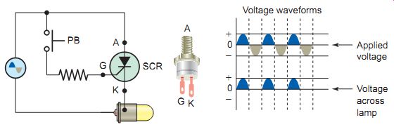
Ill. 29 SCR operated from an AC source. Voltage waveforms; Applied voltage
-- Voltage across lamp
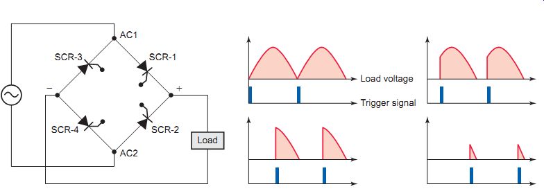
Ill. 30 Single-phase, fully controlled SCR bridge
rectifier circuit. Load voltage; Trigger signal
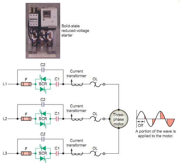
Ill. 31 Solid-state reduced-voltage motor starter. Solid-state reduced-voltage
starter; A portion of the wave is applied to the motor. Current transformer
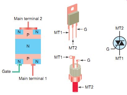
Ill. 32 Triac. Main terminal 2; Main terminal 1
Ill. 33
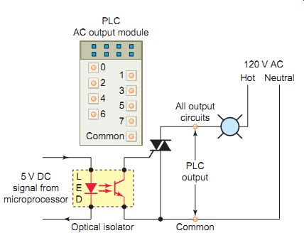
Ill. 34 Triac switching of PLC output module. 5 V DC signal from microprocessor;
Common; Optical isolator; PLC AC output module; All output circuits; PLC
output
Triac
The triac is a three-terminal device essentially equivalent to two SCRs joined in reverse parallel (paralleled but with the polarity reversed) and with their gates connected together.
The result is a bidirectional electronic switch that can be used to provide load current during both halves of the AC supply voltage. Triac connections, shown in Ill. 32, are called main terminal 1 (MT1), main terminal 2 (MT2), and gate (G). The leads are designated this way since the triac acts like two opposing diodes when it’s turned on and neither lead always acts like a cathode or an anode. Gate current is used to control current from MT1 to MT2. From terminal MT1 to MT2 the current must pass through an NPNP series of layers or a PNPN series of layers. The gate is connected to the same end as MT1, which is important to remember when you connect the triac control circuit. Terminal MT1 is the reference point for measurement of voltage and current at the gate terminal.
The triac may be triggered into conduction by either a positive or a negative voltage applied to its gate electrode.
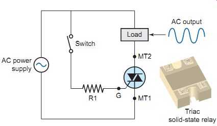
Once triggered, the device continues to conduct until the current through it drops below a certain threshold value, such as at the end of a half-cycle of the alternating current (AC) mains power. This makes the triac very convenient for switching AC loads. The triac is an almost ideal component for controlling AC power loads with a high (on/off) duty cycle. Using a triac eliminates completely the contact sticking, bounce, and wear associated with conventional electro mechanical relays. The schematic of a triac switching circuit is shown in Ill. 33. Maximum output is obtained by utilizing both half-waves of the AC input voltage. The operation of the circuit can be summarized as follows:
• The circuit provides random (anywhere in half cycle) fast turn-on of AC loads.
• When the switch is closed, a small control current will trigger the triac to conduct. Resistor R1 is provided to limit gate current to a small control current value.
• When the switch is then opened, the triac turns off when the AC supply voltage and holding current drop to zero, or reverse polarity.
• In this way large currents can be controlled even with a small switch, because the switch will have to handle only the small control current needed to turn on the triac.
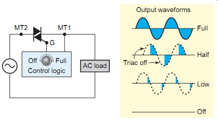
Ill. 35 Triac variable AC control circuit. Output waveforms; Control
logic
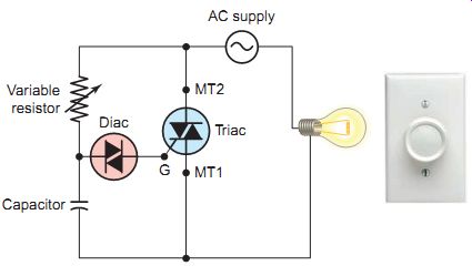
Ill. 36 Triac/diac lamp dimmer. The Leviton Manufacturing Company, Variable
resistor; Capacitor; AC supply
The output module of a programmable logic controller (PLC) serves as the link between the PLC's microprocessor and field load devices. Ill. 34 shows a triac used to switch AC high voltage and current, controlling the on/off state of the lamp. The optical isolator separates the output signal from the PLC processor circuit from the field load devices. The operation of the circuit can be summarized as follows:
• As part of its normal operation, the processor sets the outputs on or off according to the logic program.
• When the processor calls for the lamp to be on, a small voltage is applied across the LED of the optical isolator.
• The LED emits light, which switches the phototransistor into conduction.
• This in turn switches the triac into conduction to turn on the lamp.
The schematic circuit of Ill. 35 illustrates how a triac can be used to control the amount of power applied to an AC load. When used for this type of application, a control logic triggering circuit is needed to ensure that the triac conducts at the proper time. The operation of the circuit can be summarized as follows:
• The trigger circuit controls the point on the AC waveform at which the triac is switched on. It proportionally turns on a percentage of each power line half-cycle.
• The resulting waveform is still alternating current, but the average current value is adjustable.
• Since the trigger can cause it to trigger current in either direction, it’s an efficient power controller from essentially zero to full power.
• In universal motor circuits, varying the current will change the speed of the motor.
The diac is a two-terminal device that behaves like two series diodes connected in opposite directions. Cur rent flows through the diac (in either direction) when the voltage across it reaches its rated breakover voltage . The current pulse produced when the diac changes from a nonconducting to a conducting state is used for SCR and triac gate triggering.
Typically, light dimmers are manufactured with a triac as the power control device. A light dimmer works by essentially chopping parts out of the AC voltage. This allows only parts of the waveform to pass to the lamp.
The brightness of the lamp is determined by the power transferred to it, so the more the waveform is chopped, the more it dims. A simplified triac/diac incandescent lamp dimmer circuit is shown in Ill. 36. The operation of the circuit can be summarized as follows:
• With the variable resistor at its lowest value (mini mum resistance), the capacitor will charge rapidly at the beginning of each half-cycle of the AC voltage.
• When the voltage across the capacitor reaches the breakover voltage of the diac, the capacitor voltage discharges through the gate of the triac.
• Thus, the triac conducts early in each half-cycle and remains on to the end of each half-cycle.
• As a result, current will flow through the lamp for most of each half-cycle and produce maximum lamp brightness.
• If the resistance of the variable resistor is increased, the time required to charge the capacitor to the breakover voltage of the diac increases.
• This causes the triac to fire later in each half-cycle.
So, the length of time current flows through the lamp is reduced, and less light is emitted.
• The diac prevents any gate current until the triggering voltage has reached a certain repeatable level in either direction.
The average current and voltage rating for triacs is much smaller than that for SCRs. Also, triacs are designed to operate at much lower switching frequencies than SCRs and have more difficulty switching power to highly inductive loads.
Triacs, like SCRs, usually fail shorted rather than open.
Shorted triacs can usually be detected with an ohmmeter check. Measure the MT1 to MT2 resistance in both directions; a good triac should measure near infinity in both directions. Like SCRs, triacs can fail in other-possibly peculiar-ways, so substitution or bypassing may be necessary to rule out all possibilities.
PART 3 Review Questions
1. In what way does the operation of a thyristor differ from that of a transistor?
2. What are the two most popular types of thyristor?
3. What are the similarities and differences between an SCR and diode?
4. Compare the way in which the control of an SCR is different when operated from an AC than when operated from a DC supply.
5. Name three common SCR case styles.
6. How are two SCRs connected in antiparallel and what purpose does this connection serve?
7. State the most common failed state (short or open)
for both SCRs and triacs. How can an ohmmeter be used to test for this defective condition?
8. SCRs are unidirectional devices while triacs are bidirectional. What does this mean?
9. In what way is the gate triggering of an SCR different from that of a triac?
10. List some of the advantages of switching AC loads with a solid-state triac relay over switching with electromechanical types.
11. Give a brief explanation of how a triac is operated to control the amount of power applied to an AC load.
12. When will a diac conduct current?
13. List some of the limitations of triacs have compared to SCRs.
Cont to part d