AMAZON multi-meters discounts AMAZON oscilloscope discounts
As we have seen in Section 4.2.1, a synchronous machine is an ac machine whose speed under steady-state conditions is proportional to the frequency of the current in its armature. The rotor, along with the magnetic field created by the dc field current on the rotor, rotates at the same speed as, or in synchronism with, the rotating magnetic field produced by the armature currents, and a steady torque results. An elementary picture of how a synchronous machine works is given in Section 4.2.1 with emphasis on torque production in terms of the interactions between the machine's magnetic fields.
Analytical methods of examining the steady-state performance of polyphase synchronous machines will be developed in this section. Initial consideration will be given to cylindrical-rotor machines; the effects of salient poles are taken up in Sections 6 and 7.
1. INTRODUCTION TO POLYPHASE SYNCHRONOUS MACHINES
As indicated in Section 4.2.1, a synchronous machine is one in which alternating current flows in the armature winding, and dc excitation is supplied to the field winding. The armature winding is almost invariably on the stator and is usually a three-phase winding, as discussed in Section 4. The field winding is on the rotor.
The cylindrical-rotor construction shown in Figs. 4.10 and 4.11 is used for two- and four-pole turbine generators. The salient-pole construction shown in Fig. 4.9 is best adapted to multipolar, slow-speed, hydroelectric generators and to most synchronous motors. The dc power required for excitation--approximately one to a few percent of the rating of the synchronous machine m is supplied by the excitation system.
In older machines, the excitation current was typically supplied through slip rings from a dc machine, referred to as the exciter, which was often mounted on the same shaft as the synchronous machine. In more modern systems, the excitation is supplied from ac exciters and solid-state rectifiers (either simple diode bridges or phase-controlled rectifiers). In some cases, the rectification occurs in the stationary frame, and the rectified excitation current is fed to the rotor via slip tings. In other systems, referred to as brushless excitation systems, the alternator of the ac exciter is on the rotor, as is the rectification system, and the current is supplied directly to the field-winding without the need for slip tings. One such system is described in Section D. As is discussed in Section 4, a single synchronous generator supplying power to an impedance load acts as a voltage source whose frequency is determined by the speed of its mechanical drive (or prime mover), as can be seen from Eq. 4.2.
From Eqs. 4.42, 4.44, and 4.50, the amplitude of the generated voltage is proportional to the frequency and the field current. The current and power factor are then determined by the generator field excitation and the impedance of the generator and load.
Synchronous generators can be readily operated in parallel, and, in fact, the electricity supply systems of industrialized countries typically have scores or even hundreds of them operating in parallel, interconnected by thousands of miles of transmission lines, and supplying electric energy to loads scattered over areas of many thousands of square miles. These huge systems have grown in spite of the necessity for designing the system so that synchronism is maintained following disturbances and the problems, both technical and administrative, which must be solved to coordinate the operation of such a complex system of machines and personnel. The principal reasons for these interconnected systems are reliability of service and economies in plant investment and operating costs.
When a synchronous generator is connected to a large interconnected system containing many other synchronous generators, the voltage and frequency at its armature terminals are substantially fixed by the system. As a result, armature currents will produce a component of the air-gap magnetic field which rotates at synchronous speed (Eq. 4.41) as determined by the system electrical frequency fe. As is discussed in Section 4, for the production of a steady, unidirectional electromechanical torque, the fields of the stator and rotor must rotate at the same speed, and therefore the rotor must turn at precisely synchronous speed. Because any individual generator is a small fraction of the total system generation, it cannot significantly affect the system voltage or frequency. It is thus often useful, when studying the behavior of an individual generator or group of generators, to represent the remainder of the system as a constant-frequency, constant-voltage source, commonly referred to as an infinite bus.
Many important features of synchronous-machine behavior can be understood from the analysis of a single machine connected to an infinite bus. The steady-state behavior of a synchronous machine can be visualized in terms of the torque equation. From Eq. 4.81, with changes in notation appropriate to synchronous-machine theory,

(Eq. 1)
...where (I) R -resultant air-gap flux per pole Ff = mmf of the dc field winding ...
phi R RF = electrical phase angle between magnetic axes of (I)
The minus sign of Eq. 4.81 has been omitted with the understanding that the electromechanical torque acts in the direction to bring the interacting fields into alignment. In normal steady-state operation, the electromechanical torque balances the mechanical torque applied to the shaft. In a generator, the prime-mover torque acts in the direction of rotation of the rotor, pushing the rotor mmf wave ahead of the resultant air-gap flux. The electromechanical torque then opposes rotation. The opposite situation exists in a synchronous motor, where the electromechanical torque is in the direction of rotation, in opposition to the retarding torque of the mechanical load on the shaft.
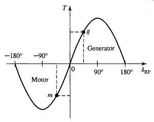
FIG. 1 Torque-angle characteristic.
Variations in the electromechanical torque result in corresponding variations in the torque angle, -RF, as seen from Eq. 1. The relationship is shown in the form of a torque-angle curve in FIG. 1, where the field current (rotor mmf) and resultant airgap flux are assumed constant. Positive values of torque represent generator action, corresponding to positive values of ~RF for which the rotor mmf wave leads the resultant air-gap flux.
As the prime-mover torque is increased, the magnitude of ~RF must increase until the electromechanical torque balances the shaft torque. The readjustment process is actually a dynamic one, requiting a change in the mechanical speed of the rotor, typically accompanied by a damped mechanical oscillation of the rotor about its new steady-state torque angle. This oscillation is referred to as a hunting transient. In a practical machine undergoing such a transient, some changes in the amplitudes of the resultant flux-density and field-winding mmf wave may also occur because of various factors such as saturation effects, the effect of the machine leakage impedance, the response of the machine's excitation system, and so on. To emphasize the fundamental principles of synchronous-machine operation, such effects will be neglected in the present discussion.
The adjustment of the rotor to its new angular position following a load change can be observed experimentally in the laboratory by viewing the machine rotor with stroboscopic light triggered from the applied armature voltage (thus having a flashing frequency which causes the rotor to appear stationary when it is turning at its normal synchronous speed). Alternatively, electronic sensors can be used to determine the shaft position relative to the synchronous reference frame associated with the stator voltage. The resultant signal can be displayed on an oscilloscope or recorded with a data-acquisition system.
As can be seen from FIG. 1, an increase in prime-mover torque will result in a corresponding increase in the torque angle. When ~RF becomes 90 °, the electromechanical torque reaches its maximum value, known as the pull-out torque. Any further increase in prime-mover torque cannot be balanced by a corresponding increase in synchronous electromechanical torque, with the result that synchronism will no longer be maintained and the rotor will speed up. This phenomenon is known as loss of synchronism or pulling out of step. Under these conditions, the generator is usually disconnected from the external electrical system by the automatic operation of circuit breakers, and the prime mover is quickly shut down to prevent dangerous overspeed. Note from Eq. 1 that the value of the pull-out torque can be increased by increasing either the field current or the resultant air-gap flux. However, this cannot be done without limit; the field current is limited by the ability to cool the field winding, and the air-gap flux is limited by saturation of the machine iron.
As seen from FIG. 1, a similar situation occurs in a synchronous motor for which an increase in the shaft load torque beyond the pull-out torque will cause the rotor to lose synchronism and thus to slow down. Since a synchronous motor develops torque only at synchronous speed, it cannot be started simply by the application of armature voltages of rated frequency. In some cases, a squirrel-cage structure is included in the rotor, and the motor can be started as an induction motor and then synchronized when it is close to synchronous speed.
2. SYNCHRONOUS-MACHINE INDUCTANCES; EQUIVALENT CIRCUITS
In Section 1, synchronous-machine torque-angle characteristics are described in terms of the interacting air-gap flux and mmf waves. Our purpose now is to derive an equivalent circuit which represents the steady-state terminal volt-ampere characteristics.
A cross-sectional sketch of a three-phase cylindrical-rotor synchronous machine is shown schematically in FIG. 2. The figure shows a two-pole machine; alternatively, this can be considered as two poles of a multipole machine. The three-phase armature winding on the stator is of the same type used in the discussion of rotating magnetic fields in Section 4.5. Coils aa', bb', and cc I represent distributed windings producing sinusoidal mmf and flux-density waves in the air gap. The reference directions for the currents are shown by dots and crosses. The field winding ff' on the rotor also represents a distributed winding which produces a sinusoidal mmf and flux-density wave centered on its magnetic axis and rotating with the rotor.
When the flux linkages with armature phases a, b, c and field winding f are expressed in terms of the inductances and currents as follows,
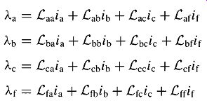
(Eq. 2)
(Eq. 3)
(Eq. 4)
(Eq. 5)
the induced voltages can be found from Faraday's law. Here, two like subscripts denote a self-inductance, and two unlike subscripts denote a mutual inductance between the two windings. The script 12 is used to indicate that, in general, both the self- and mutual inductances of a three-phase machine may vary with rotor angle, as is seen, for example, in Section C.2, where the effects of salient poles are analyzed.
Before we proceed, it is useful to investigate the nature of the various inductances.
Each of these inductances can be expressed in terms of constants which can be computed from design data or measured by tests on an existing machine.
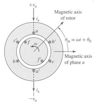
FIG. 2 Schematic diagram of a two-pole, three-phase cylindrical rotor
synchronous machine.
2.1 Rotor Self-Inductance
With a cylindrical stator, the self-inductance of the field winding is independent of the rotor position 0m when the harmonic effects of stator slot openings are neglected.
Hence

(Eq. 6)
where the italic L is used for an inductance which is independent of 0m. The component Lff0 corresponds to that portion of/2ff due to the space-fundamental component of air-gap flux. This component can be computed from air-gap dimensions and winding data, as shown in A-Section B. The additional component Ln accounts for the field-winding leakage flux.
Under transient or unbalanced conditions, the flux linkages with the field winding, Eq. 5, vary with time, and the voltages induced in the rotor circuits have an important effect on machine performance. With balanced three-phase armature currents, however, the constant-amplitude magnetic field of the armature currents rotates in synchronism with the rotor. Thus the field-winding flux linkages produced by the armature currents do not vary with time, and the voltage induced in the field winding is therefore zero. With constant dc voltage Vf applied to the field-winding terminals, the field direct current If is given by Ohm's law, If = Vf/Re.
2.2 Stator-to-Rotor Mutual Inductances
The stator-to-rotor mutual inductances vary periodically with 0me, the electrical angle between the magnetic axes of the field winding and the armature phase a as shown in FIG. 2 and as defined by Eq. 4.54. With the space-mmf and air-gap flux distribution assumed sinusoidal, the mutual inductance between the field winding f and phase a varies as cos 0me; thus

(Eq. 7)
Similar expressions apply to phases b and c, with 0me replaced by 0me 120 ° and 0me -~120 °, respectively. Attention will be focused on phase a. The inductance Laf can be calculated as discussed in A-Section B. With the rotor rotating at synchronous speed Ws (Eq. 4.40), the rotor angle will vary as

(Eq. 8)
where 60 is the angle of the rotor at time t = 0. From Eq. 4.54
(Eq. 9)
Here, O) e ~--(poles/2)Ws is the electrical frequency and ~e0 is the electrical angle of the rotor at time t 0. Thus, substituting into Eq. 7 gives

(Eq. 10)
2.3 Stator Inductances; Synchronous Inductance
With a cylindrical rotor, the air-gap geometry is independent of 0m if the effects of rotor slots are neglected. The stator self-inductances then are constant; thus ...

(Eq. 11)
... air-gap component of the phase-a self-flux linkages. The second, Lal, known as the armature-winding leakage inductance, is due to the leakage component of phase-a 1 flux linkages. The third component, ~ Laa0, is due to the phase-a flux linkages from the space-fundamental component of air-gap flux produced by currents in phases b and c. Under balanced three-phase conditions, the phase-b and -c currents are related to the current in phase a by Eq. 15. Thus the synchronous inductance is an apparent inductance in that it accounts for the flux linkages of phase a in terms of the current in phase a, even though some of this flux linkage is due to currents in phases a and b.
Hence, although synchronous inductance appears in that role in Eq. 18, it is not the self-inductance of phase a alone.
The significance of the synchronous inductance can be further appreciated with reference to the discussion of rotating magnetic fields in Section 4.5.2, where it was shown that under balanced three-phase conditions, the armature currents create a rotating magnetic flux wave in the air gap of magnitude equal to 3 times the magnitude of that due to phase a alone, the additional component being due to the phase-b and -c currents. This corresponds directly to the 3 Laa0 component of the synchronous inductance in Eq. 17; this component of the synchronous inductance accounts for the total space-fundamental air-gap component of phase-a flux linkages produced by the three armature currents under balanced three-phase conditions.
2.4 Equivalent Circuit
The phase-a terminal voltage is the sum of the armature-resistance voltage drop Raia and the induced voltage. The voltage eaf induced by the field winding flux (often referred to as the generated voltage or internal voltage) can be found from the time derivative of Eq. 18 with the armature current ia set equal to zero. With dc excitation If in the field winding, substitution of Eq. 10 gives

(Eq. 19)
Using Eq. 18, the terminal voltage can then be expressed as...
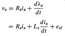
(Eq. 20)
The generated voltage eaf of Eq. 19 is at frequency We, equal to the electrical frequency of the generator terminal voltage. Its rms amplitude is given by

(Eq. 21)
Under this synchronous operating condition, all machine armature quantifies (current and flux linkage) will also vary sinusoidally in time at frequency We. Thus, we can write the above equations in term of their rms, complex amplitudes. From Eq. 19 we can write the rms complex amplitude of the generated voltage as

(Eq. 22)
Similarly, the terminal-voltage equation, Eq. 20, can be written in terms of rms complex amplitudes as

(Eq. 23)
where Xs -(De ts is known as the synchronous reactance.
An equivalent circuit in complex form is shown in FIG. 3a. The reader should note that Eq. 23 and FIG. 3a are written with the reference direction for Ia defined as positive into the machine terminals. This is known as the motor reference direction for the current.
Alternatively, the generator reference direction is defined with the reference direction for Ia chosen as positive out of the machine terminals, as shown in FIG. 3b.
Under this choice of current reference direction, Eq. 23 becomes...

(Eq. 24)
Note that these two representations are equivalent; when analyzing a particular synchronous-machine operating condition the actual current will be the same. The sign of Ia will simply be determined by the choice of reference direction. Either choice is acceptable, independent of whether the synchronous machine under investigation is operating as a motor or a generator. However, since power tends to flow into a motor, it is perhaps intuitively more satisfying to choose a reference direction with current flowing into the machine for the analysis of motor operation. The opposite is true for generator operation, for which power tends to flow out of the machine. Most of the synchronous-machine analysis techniques presented here were first developed to analyze the performance of synchronous generators in electric power systems. As a result, the generator reference direction is more common and is generally used from this point on in the text.
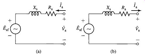
FIG. 3 Synchronous-machine equivalent circuits: (a) motor reference
direction and (b) generator reference direction.
FIG. 4 Synchronous-machine equivalent circuit showing air-gap and leakage components of synchronous reactance and air-gap voltage.
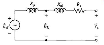
FIG. 4 shows an alternative form of the equivalent circuit in which
the synchronous reactance is shown in terms of its components. From Eq. 17
(Eq. 25)
where Xal =coLal is the armature leakage reactance and X~0 = (-o(3Laa0) is the reactance corresponding to the rotating space-fundamental air-gap flux produced by the three armature currents. The reactance X~0 is the effective magnetizing reactance of the armature winding under balanced three-phase conditions. The rms voltage/~R is the internal voltage generated by the resultant air-gap flux and is usually referred to as the air-gap voltage or the voltage "behind" leakage reactance.
It is important to recognize that the equivalent circuits of Figs. 3 and 4 are single-phase, line-to-neutral equivalent circuits for a three-phase machine operating under balanced, three-phase conditions. Thus, once the phase-a voltages and currents are found, either from the equivalent circuit or directly from the voltage equations (Eqs. 23 and 24), the currents and voltages for phases b and c can be found simply by phase-shifting those of phase a by -120 ° and 120 ° respectively. Similarly, the total three-phase power of the machine can be found simply by multiplying that of phase a by three, unless the analysis is being performed in per unit (see Section 2.9), in which case the three-phase, per-unit power is equal to that found from solving for phase a alone and the factor of three is not needed.
3. OPENAND SHORT-CIRCUIT CHARACTERISTICS
The fundamental characteristics of a synchronous machine can be determined by a pair of tests, one made with the armature terminals open-circuited and the second with the armature terminals short-circuited. These tests are discussed here. Except for a few remarks on the degree of validity of certain assumptions, the discussions apply to both cylindrical-rotor and salient-pole machines.
3.1 Open-Circuit Saturation Characteristic and No-Load Rotational Losses
Like the magnetization curve for a dc machine, the open-circuit characteristic (also referred to as the open-circuit saturation curve) of a synchronous machine is a curve of the open-circuit armature terminal voltage (either in volts or in per unit) as a function of the field excitation when the machine is running at synchronous speed, as shown by curve occ in FIG. 5. Typically, the base voltage is chosen equal to the rated voltage of the machine.
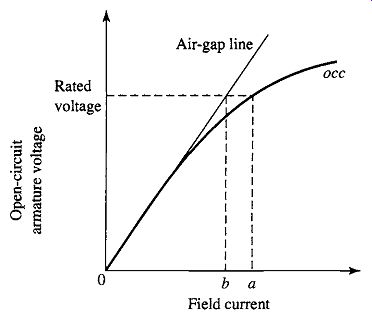
FIG. 5 Open-circuit characteristic of a synchronous machine.
The open-circuit characteristic represents the relation between the space-fundamental component of the air-gap flux and the mmf acting on the magnetic circuit when the field winding constitutes the only mmf source. Note that the effects of magnetic saturation can be clearly seen; the characteristic bends downward with increasing field current as saturation of the magnetic material increases the reluctance of the flux paths in the machine and reduces the effectiveness of the field current in producing magnetic flux. As can be seen from FIG. 5, the open-circuit characteristic is initially linear as the field current is increased from zero. This portion of the curve (and its linear extension for higher values of field current) is known as the air-gap line. It represents the machine open-circuit voltage characteristic corresponding to unsaturated operation. Deviations of the actual open-circuit characteristic from this curve are a measure of the degree of saturation in the machine.
Note that with the machine armature winding open-circuited, the terminal voltage is equal to the generated voltage Eaf. Thus the open-circuit characteristic is a measurement of the relationship between the field current If and Eaf. It can therefore provide a direct measurement of the field-to-armature mutual inductance Laf.
------
When the machine is an existing one, the open-circuit characteristic is usually determined experimentally by driving the machine mechanically at synchronous speed with its armature terminals on open circuit and by reading the terminal voltage corresponding to a series of values of field current. If the mechanical power required to drive the synchronous machine during the open-circuit test is measured, the no-load rotational losses can be obtained. These losses consist of friction and windage losses associated with rotation as well as the core loss corresponding to the flux in the machine at no load. The friction and windage losses at synchronous speed are constant, while the open-circuit core loss is a function of the flux, which in turn is proportional to the open-circuit voltage.
The mechanical power required to drive the machine at synchronous speed and unexcited is its friction and windage loss. When the field is excited, the mechanical power equals the sum of the friction, windage, and open-circuit core loss. The open-circuit core loss therefore can be found from the difference between these two values of mechanical power. A typical curve of open-circuit core loss as a function of open-circuit voltage takes the form of that found in FIG. 6.
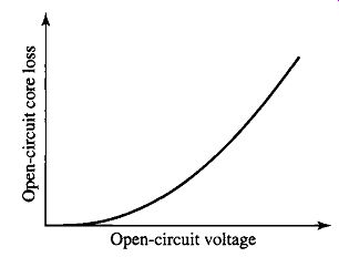
FIG. 6 Typical form of an open-circuit core-loss curve.
3.2 Short-Circuit Characteristic and Load Loss
A short-circuit characteristic can be obtained by applying a three-phase short circuit through suitable current sensors to the armature terminals of a synchronous machine.
With the machine driven at synchronous speed, the field current can be increased and a plot of armature current versus field current can be obtained. This relation is known as the short-circuit characteristic. An open-circuit characteristic occ and a short-circuit characteristic scc are shown in FIG. 7.
With the armature short-circuited, Va = 0 and, from Eq. 24 (using the generator reference direction for current)

(Eq. 26)
The corresponding phasor diagram is shown in FIG. 8. Because the resistance is much smaller than the synchronous reactance, the armature current lags the excitation voltage by very nearly 90 °. Consequently the armature-reaction-mmf wave is very nearly in line with the axis of the field poles and in opposition to the field mmf, as shown by phasors ,4 and P representing the space waves of armature reaction and field mmf, respectively.
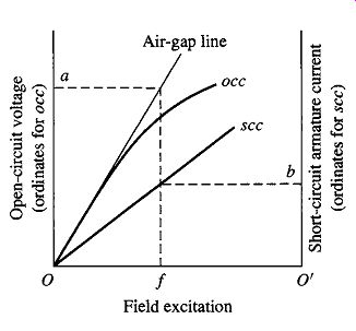
FIG. 7 Open- and short-circuit characteristics of a synchronous machine.
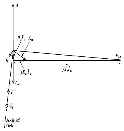
FIG. 8 Phasor diagram for short-circuit conditions.
The resultant mmf creates the resultant air-gap flux wave which generates the air-gap voltage/~R (see FIG. 4) equal to the voltage consumed in armature resistance Ra and leakage reactance Xal; as an equation,

(Eq. 27)
In many synchronous machines the armature resistance is negligible, and the leakage reactance is between 0.10 and 0.20 per unit; a representative value is about 0.15 per unit. That is, at rated armature current the leakage reactance voltage drop is about 0.15 per unit. From Eq. 27, therefore, the air-gap voltage at rated armature current on short circuit is about 0.15 per unit; i.e., the resultant air-gap flux is only about 0.15 times its normal voltage value. Consequently, the machine is operating in an unsaturated condition. The short-circuit armature current, therefore, is directly proportional to the field current over the range from zero to well above rated armature current; it is thus a straight line as can be seen in FIG. 7.
The unsaturated synchronous reactance (corresponding to unsaturated operating conditions within the machine) can be found from the open- and short-circuit characteristics. At any convenient field excitation, such as Of in FIG. 7, the armature current on short circuit is O'b, and the unsaturated generated voltage for the same field current corresponds to O a, as read from the air-gap line. Note that the voltage on the air-gap line should be used because the machine is assumed to be operating in an unsaturated condition. If the line-to-neutral voltage corresponding to O a is Va, ag and the armature current per phase corresponding to O'b is la, sc, then from Eq. 26, with armature resistance neglected, the unsaturated synchronous reactance

(Eq. 28)
… where the subscripts "ag" and "sc" indicate air-gap line conditions and short-circuit conditions, respectively. If Va,ag and Ia, sc are expressed in per unit, the synchronous reactance will be in per unit. If Va, ag and la, sc are expressed in rms line-to-neutral volts and rms amperes per phase, respectively, the synchronous reactance will be in ohms per phase.
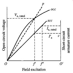
FIG. 9 open- and short-circuit characteristics showing equivalent magnetization
line for saturated operating conditions.
Note that the synchronous reactance in ohms is calculated by using the phase or line-to-neutral voltage. Often the open-circuit saturation curve is given in terms of the line-to-line voltage, in which case the voltage must be converted to the line-to-neutral value by dividing by ~/-3.
For operation at or near rated terminal voltage, it is sometimes assumed that the machine is equivalent to an unsaturated one whose magnetization line is a straight line through the origin and the rated-voltage point on the open-circuit characteristic, as shown by the dashed line Op in FIG. 9. According to this approximation, the saturated value of the synchronous reactance at rated voltage (Eq. 29) ...
… where I a' is the armature current Otc read from the short-circuit characteristic at the field current Of' corresponding to Va, rated on the open-circuit characteristic, as shown in FIG. 9. As with the unsaturated synchronous reactance, if Va, rated and I a' are expressed in per unit, the synchronous reactance will be in per unit. If Va, rated and I a' are expressed in rms line-to-neutral volts and rms amperes per phase, respectively, the synchronous reactance will be in ohms per phase. This method of handling the effects of saturation, which assumes that the effects of saturation can be described by a single value of saturated reactance, usually gives satisfactory results when great accuracy is not required.
The short-circuit ratio (SCR) is defined as the ratio of the field current required for rated voltage on open circuit to the field current required for rated armature current on short circuit. That is, in FIG. 9 Of' SCR = (Eq. 30) Of" It can be shown that the SCR is the reciprocal of the per-unit value of the saturated synchronous reactance found from Eq. 29. It is common to refer to the field current Of' required to achieve rated-open-circuit voltage as AFNL (Amperes Field No Load) and the field current Of" required to achieve rated-short-circuit current as AFSC (Amperes Field Short Circuit). Thus, the short-circuit ratio can also be written as

(Eq. 31)
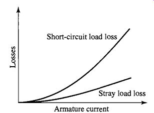
FIG. 10 Typical form of short-circuit load loss and stray load loss
curves.
If the mechanical power required to drive the machine is measured while the short-circuit test is being made, information can be obtained regarding the losses caused by the armature current. Because the machine flux level is low under shortcircuit conditions, the core loss under this condition is typically considered to be negligible. The mechanical power required to drive the synchronous machine during the short-circuit test then equals the sum of friction and windage loss (determined from the open-circuit test at zero field current) plus losses caused by the armature current. The losses caused by the armature current can then be found by subtracting friction and windage from the driving power. The losses caused by the short-circuit armature current are known collectively as the short-circuit load loss. A curve showing the typical form of short-circuit load loss plotted against armature current is shown in FIG. 10. Typically, it is approximately parabolic with armature current.
The short-circuit load loss consists of I^2R loss in the armature winding, local core losses caused by the armature leakage flux, and the very small core loss caused by the resultant flux. The dc resistance loss can be computed if the dc resistance is measured and corrected, when necessary, for the temperature of the windings during the short-circuit test. For copper conductors

(Eq. 32)
… where RT and Rt are the resistances at Celsius temperatures T and t, respectively.
If this dc resistance loss is subtracted from the short-circuit load loss, the difference will be the loss due to skin effect and eddy currents in the armature conductors plus the local core losses caused by the armature leakage flux. This difference between the short-circuit load loss and the dc resistance loss is the additional loss caused by the alternating current in the armature. It is the stray-load loss described in A-Section D, commonly considered to have the same value under normal load conditions as on short circuit. It is a function of the armature current, as shown by the curve in FIG. 10.
As with any ac device, the effective resistance of the armature Ra, eff can be computed as the power loss attributable to the armature current divided by the square of the current. On the assumption that the stray load loss is a function of only the armature current, the effective resistance of the armature can be determined from the shortcircuit load loss: short-circuit load loss
(Eq. 33)
If the short-circuit load loss and armature current are in per unit, the effective resistance will be in per unit. If they are in watts per phase and amperes per phase, respectively, the effective resistance will be in ohms per phase. Usually it is sufficiently accurate to find the value of Ra, eff at rated current and then to assume it to be constant.
4. STEADY-STATE POWER-ANGLE CHARACTERISTICS
The maximum power a synchronous machine can deliver is determined by the maximum torque which can be applied without loss of synchronism with the external system to which it is connected. The purpose of this section is to derive expressions for the steady-state power limits of synchronous machines in simple situations for which the external system can be represented as an impedance in series with a voltage source.
Since both the external system and the machine itself can be represented as an impedance in series with a voltage source, the study of power limits becomes merely a special case of the more general problem of the limitations on power flow through a series impedance. The impedance will include the synchronous impedance of the synchronous machine as well as an equivalent impedance of the external system (which may consist of transmission lines and transformer banks as well as additional synchronous machines). Consider the simple circuit of FIG. 11 a, consisting of two ac voltages/~ 1 and
/~2 connected by an impedance Z = R -F jX through which the current is i. The phasor diagram is shown in FIG. 1 lb. Note that in this phasor diagram, the reference direction for positive angles is counter-clockwise. Thus, in FIG. 11 b, the angle 6 is positive while the angle 4) can be seen to be negative.
The power P2 delivered through the impedance to the load-end voltage source

(Eq. 34)
where 4) is the phase angle of i with respect to/~2. The phasor current is
(Eq. 35)
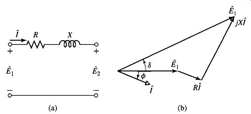
FIG. 11 (a) Impedance interconnecting two voltages; (b) phasor diagram.
If the phasor voltages and the impedance are expressed in polar form,

(Eq. 36)
(Eq. 37)
(Eq. 38)
where 8 is the phase angle by which E1 leads/~2 and
4~z = tan -1 (X/R) is the phase angle of the impedance Z, then:

(Eq. 39)
Taking the real part of Eq. 39 gives E~ E2 I cos q~ = cos (8 q~z) ~ cos (-q~z) (Eq. 40)
Noting that cos (-4~z)=cos4~z = R/IZI we see that substitution of Eq. 40 in Eq. 34 gives

(Eq. 41)
(Eq. 42)
(Eq. 43)
Similarly power P1 at source end/~1 of the impedance can be expressed as
(Eq. 44)
If, as is frequently the case, the resistance is negligible, then
(Eq. 45)
X Equation 45 is a very important equation in the study of synchronous machines and indeed in the study of ac power systems in general. When applied to the situation of a synchronous machine connected to an ac system, Eq. 45 is commonly referred to as the power-angle characteristic for a synchronous machine, and the angle 8 is known as the power angle. If the resistance is negligible and the voltages are constant, then from Eq. 45 the maximum power transfer
(Eq. 46)
occurs when ~ = 4-90 °. Note that if ~ is positive, E1 leads E2 and, from Eq. 45, power flows from source E 1 to E2. Similarly, when ~ is negative, E1 lags E2 and power flows from source E2 to E1.
Equation 45 is valid for any voltage sources E1 and E2 separated by a reactive impedance j X. Thus for a synchronous machine with generated voltage J~af and synchronous reactance Xs connected to a system whose Thevenin equivalent is a voltage source VEQ in series with a reactive impedance j XEQ, as shown in FIG. 12, the power-angle characteristic can be written
~ (Eq. 47)
... where P is the power transferred from the synchronous machine to the system and is the phase angle of/~af with respect to f'EQ. In a similar fashion, it is possible to write a power-angle characteristic in terms of Xs, Eaf, the terminal voltage Va, and the relative angle between them, or alternatively XEQ, Va and VEQ and their relative angle. Although these various expressions are equally valid, they are not equally useful. For example, while Eaf and VEQ remain constant as P is varied, Va will not. Thus, while Eq. 47 gives an easily solved relation between P and d;, a power-angle characteristic based upon Va cannot be solved without an additional expression relating Va to P. It should be emphasized that the derivation of Eqs. 34 to 47 is based on a single-phase ac circuit. For a balanced three-phase system, if E1 and E2 are the line-neutral voltages, the results must be multiplied by three to get the total three-phase power; alternatively E1 and E2 can be expressed in terms of the line-to-line voltage (equal to ~/3 times the line-neutral voltage), in which case the equations give three-phase power directly.
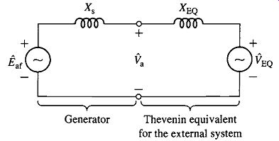
FIG. 12 Equivalent-circuit representation of a synchronous machine
connected to an external system.
When the power expression of Eq. 45 is compared with the expression of Eq. 1 for torque in terms of interacting flux and mmf waves, they are seen to be of the same form. This is no coincidence. Remember that torque and power are proportional when, as here, speed is constant. What we are really saying is that Eq. 1, applied specifically to an idealized cylindrical-rotor machine and translated to circuit terms, becomes Eq. 45. A quick mental review of the background of each relation should show that they stem from the same fundamental considerations.
From Eq. 47 we see that the maximum power transfer associated with synchronous-machine operation is proportional to the magnitude of the system voltage, corresponding to VEQ, as well as to that of the generator internal voltage Eaf.
Thus, for constant system voltage, the maximum power transfer can be increased by increasing the synchronous-machine field current and thus the internal voltage. Of course, this cannot be done without limit; neither the field current nor the machine fluxes can be raised past the point where cooling requirements fail to be met.
In general, stability considerations dictate that a synchronous machine achieve steady-state operation for a power angle considerably less than 90 °. Thus, for a given system configuration, it is necessary to ensure that the machine will be able to achieve its rated operation and that this operating condition will be within acceptable operating limits for both the machine and the system.
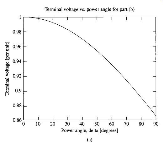
FIG. 13 Example 6. (a) MATLAB plot of terminal voltage vs. for part (b). (b)
MATLAB plot of Eaf vs. power for part (c).
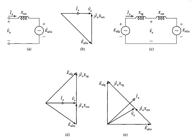
FIG. 14 Equivalent circuits and phasor diagrams for Example 7.
5. STEADY-STATE OPERATING CHARACTERISTICS
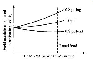
FIG. 15 Characteristic form of synchronous-generator compounding curves.
The principal steady-state operating characteristics of a synchronous machine are described by the interrelations between terminal voltage, field current, armature current, power factor, and efficiency. A selection of performance curves of importance in practical application of synchronous machines are presented here.
Consider a synchronous generator delivering power at constant frequency and rated terminal voltage to a load whose power factor is constant. The curve showing the field current required to maintain rated terminal voltage as the constant-power-factor load is varied is known as a compounding curve. The characteristic form of three compounding curves at various constant power factors are shown in FIG. 15.
Synchronous generators are usually rated in terms of the maximum apparent power (kVA or MVA) load at a specific voltage and power factor (often 80, 85, or 90 percent lagging) which they can carry continuously without overheating. The real power output of the generator is usually limited to a value within the apparent power rating by the capability of its prime mover. By virtue of its voltage-regulating system (which controls the field current in response to the measured value of terminal voltage), the machine normally operates at a constant terminal voltage whose value is within 4-5 percent of rated voltage. When the real-power loading and voltage are fixed, the allowable reactive-power loading is limited by either armature- or field-winding heating. A typical set of capability curves for a large, hydrogen-cooled turbine generator is shown in FIG. 16. They give the maximum reactive-power loadings corresponding to various real power loadings with operation at rated terminal voltage.
Note that the three-curves seen in the figure correspond to differing pressure of the hydrogen cooling gas. As can be seen, increasing the hydrogen pressure improves cooling and permits a larger overall loading of the machine.
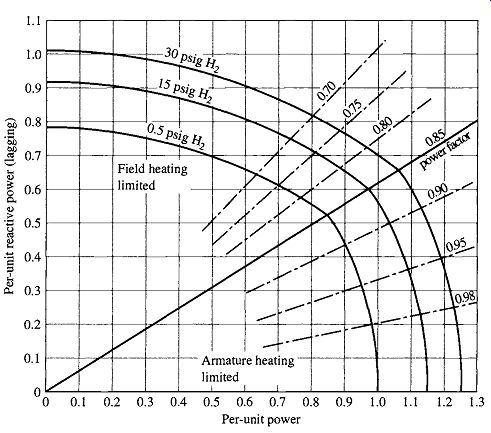
FIG. 16 Capability curves of an 0.85 power factor, 0.80 short-circuit
ratio, hydrogen-cooled turbine generator. Base MVA is rated MVA at 0.5 psig
hydrogen.
Armature-winding heating is the limiting factor in the region from unity to rated power factor (0.85 lagging power factor in FIG. 16). For example, for a given real-power loading, increasing the reactive power past a point on the armature-heating limited portion of the capability curve will result in an armature current in excess of that which can be successfully cooled, resulting in armature-winding temperatures which will damage the armature-winding insulation and degrade its life. Similarly, for lower power factors, field-winding heating is the limiting factor.
Capability curves provide a valuable guide both to power system planners and to operators. As system planners consider modifications and additions to power systems, they can readily see whether the various existing or proposed generators can safely supply their required loadings. Similarly, power system operators can quickly see whether individual generators can safely respond to changes in system loadings which occur during the normal course of system operation.
The derivation of capability curves such as those in FIG. 16 can be seen as follows. Operation under conditions of constant terminal voltage and armature current (at the maximum value permitted by heating limitations) corresponds to a constant value of apparent output power determined by the product of terminal voltage and current. Since the per-unit apparent power is given by Apparent power

(Eq. 48)
... where P represents the per-unit real power and Q represents the per-unit reactive power, we see that a constant apparent power corresponds to a circle centered on the origin on a plot of reactive power versus real power. Note also from Eq. 48, that, for constant terminal voltage, constant apparent power corresponds to constant armature-winding current and hence constant armature-winding heating. Such a circle, corresponding to the maximum acceptable level of armature heating, is shown in FIG. 17.
Similarly, consider operation when terminal voltage is constant and field current (and hence Eaf) is limited to a maximum value, also determined by heating limitations.
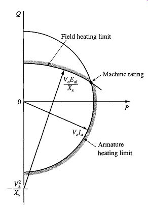
FIG. 17 Construction used for the derivation of a synchronous generator
capability curve.
In per unit, P j Q = I3"aia (Eq. 49)
From Eq. 24 (with Ra = 0)
(Eq.50)
Equations 49 and 50 can be solved to yield
(Eq. 51)
This equation corresponds to a circle centered at Q = -(V2/Xs) in FIG. 17 and determines the field-heating limitation on machine operation shown in FIG. 16. It is common to specify the rating (apparent power and power factor) of the machine as the point of intersection of the armature and field-heating limitation curves.
For a given real-power loading, the power factor at which a synchronous machine operates, and hence its armature current, can be controlled by adjusting its field excitation. The curve showing the relation between armature current and field current at a constant terminal voltage and with a constant real power is known as a V curve because of its characteristic shape. A family of V curves for a synchronous generator takes the form of those shown in FIG. 18.
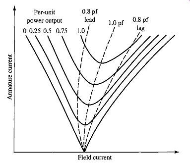
FIG. 18 Typical form of synchronous-generator V curves.
For constant power output, the armature current is minimum at unity power factor and increases as the power factor decreases. The dashed lines are loci of constant power factor; they are the synchronous-generator compounding curves (see FIG. 15)
showing how the field current must be varied as the load is changed to maintain constant power factor. Points to the right of the unity-power-factor compounding curve correspond to over-excitation and lagging power factor; points to the left correspond to under-excitation and leading power factor. Synchronous-motor V curves and compounding curves are very similar to those of synchronous generators. In fact, if it were not for the small effects of armature resistance, motor and generator compounding curves would be identical except that the lagging and leading-power-factor curves would be interchanged.
As in all electromechanical machines, the efficiency of a synchronous machine at any particular operating point is determined by the losses which consist of I^2R losses in the windings, core losses, stray-load losses, and mechanical losses. Because these losses change with operating condition and are somewhat difficult to measure accurately, various standard procedures have been developed to calculate the efficiency of synchronous machines. 2 The general principles for these calculations are described in Section D.
6. EFFECTS OF SALIENT POLES; INTRODUCTION TO DIRECTAND QUADRATURE-AXIS THEORY
The essential features of salient-pole machines are developed in this section based on physical reasoning. A mathematical treatment, based on an inductance formulation like that presented in Section 2, is given in A-Section C, where the dq0 transformation is developed.
6.1 Flux and MMF Waves
The flux produced by an mmf wave in a uniform-air-gap machine is independent of the spatial alignment of the wave with respect to the field poles. In a salient-pole machine, such as that shown schematically in FIG. 20, however, the preferred direction of magnetization is determined by the protruding field poles. The permeance along the polar axis, commonly referred to as the rotor direct axis, is appreciably greater than that along the interpolar axis, commonly referred to as the rotor quadrature axis.
Note that, by definition, the field winding produces flux which is oriented along the rotor direct axis. Thus, when phasor diagrams are drawn, the field-winding mmf and its corresponding flux (~)f are found along the rotor direct axis. The generated internal voltage is proportional to the time derivative of the field-winding flux, and thus its phasor Eaf leads the flux (~)f by 90 °. Since by convention the quadrature axis leads the direct axis by 90 °, we see that the generated-voltage phasor Eaf lies along the quadrature axis. Thus a key point in the analysis of synchronous-machine phasor diagrams is that, by locating the phasor J~af, the location of both the quadrature axis and the direct axis is immediately determined. This forms the basis of the direct- and quadrature-axis formulation for the analysis of salient-pole machines in which all machine voltages and currents can be resolved into their direct- and quadrature-axis components.
The armature-reaction flux wave 4)ar lags the field flux wave by a space angle of 90 ° + (Plag, where (~lag is the time-phase angle by which the armature current lags the generated voltage. If the armature current Ia lags the generated voltage Eaf by 90 °, the armature-reaction flux wave is directly opposite the field poles and in the opposite direction to the field flux 4)f, as shown in the phasor diagram of FIG. 20a.
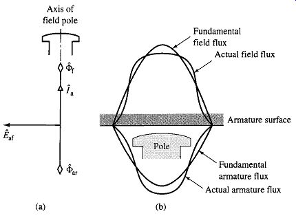
FIG. 20 Direct-axis air-gap fluxes in a salient-pole synchronous machine.
The corresponding component flux-density waves at the armature surface produced by the field current and by the synchronously-rotating space-fundamental component of armature-reaction mmf are shown in FIG. 20b, in which the effects of slots are neglected. The waves consist of a space fundamental and a family of odd-harmonic components. In a well-designed machine the harmonic effects are usually small.
Accordingly, only the space-fundamental components will be considered. It is the fundamental components which are represented by the flux-per-pole phasors (I)f and ~a~ in FIG. 20a.
Conditions are quite different when the armature current is in phase with the generated voltage, as illustrated in the phasor diagram of FIG. 21 a. The axis of the armature-reaction wave then is opposite an interpolar space, as shown in FIG. 21 b.
The armature-reaction flux wave is badly distorted, comprising principally a fundamental and a prominent third space harmonic. The third-harmonic flux wave generates third-harmonic emf's in the armature phase (line-to-neutral) voltages. They will be of the form...

(Eq. 52)
(Eq. 53)
(Eq. 54)
Note that these third-harmonic phase voltages are equal in magnitude and in phase. Hence they do not appear as components of the line-to-line voltages, which are equal to the differences between the various phase voltages.
Because of the longer air gap between the poles and the correspondingly larger reluctance, the space-fundamental armature-reaction flux when the armature reaction is along the quadrature axis (FIG. 21) is less than the space fundamental armature-reaction flux which would be created by the same armature current if the armature flux wave were directed along the direct axis (FIG. 20). Hence, the quadrature-axis magnetizing reactance is less than that of the direct axis.
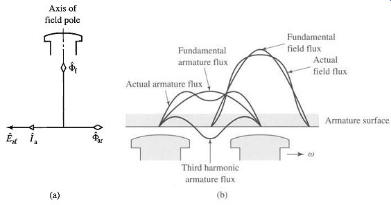
FIG. 21 Quadrature-axis air-gap fluxes in a salient-pole synchronous
machine.
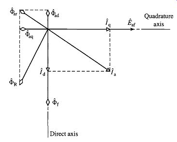
FIG. 22 Phasor diagram of a salient-pole synchronous generator.
Focusing our attention on the space-fundamental components of the air-gap flux and mmf, the effects of salient poles can be taken into account by resolving the armature current [a into two components, one along the direct axis and the other along the quadrature axis as shown in the phasor diagram of FIG. 22. This diagram is drawn for a unsaturated salient-pole generator operating at a lagging power factor. The direct-axis component id of the armature current, in time-quadrature with the generated voltage J~af, produces a component of the space-fundamental armature-reaction flux t~)ad along the axis of the field poles (the direct axis), as in FIG. 20. The quadrature-axis component iq, in phase with the generated voltage, produces a component of the space-fundamental armature-reaction flux t~aq in space-quadrature with the field poles, as in FIG. 21. Note that the subscripts d ("direct") and q ("quadrature") on the armature-reaction fluxes refer to their space phase and not to the time phase of the component currents producing them.
Thus a direct-axis quantity is one whose magnetic effect is aligned with the axes of the field poles; direct-axis mmf's produce flux along these axes. A quadrature-axis quantity is one whose magnetic effect is centered on the interpolar space. For an unsaturated machine, the armature-reaction flux t~ar is the sum of the components t~ad and t~)aq. The resultant flux t~ R is the sum of ~ar and the field flux t~f.
6.2 Phasor Diagrams for Salient-Pole Machines
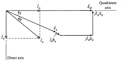
FIG. 23 Phasor diagram for a synchronous generator showing the relationship
between the voltages and the currents.
With each of the component currents Id and /~q there is associated a component synchronous-reactance voltage drop, j idXd and j iqXq respectively. The reactances Xd and Xq are, respectively, the direct and quadrature-axis synchronous reactances; they account for the inductive effects of all the space-fundamental fluxes created by the armature currents along the direct and quadrature axes, including both armature leakage and armature-reaction fluxes. Thus, the inductive effects of the direct and quadrature-axis armature-reaction flux waves can be accounted for by direct- and quadrature-axis magnetizing reactances, X¢d and X~0q respectively, similar to the magnetizing reactance X~0 of cylindrical-rotor theory. The direct- and quadrature-axis synchronous reactances are then given by ...

(Eq. 55)
(Eq. 56)
where Xa] is the armature leakage reactance, assumed to be the same for direct- and quadrature-axis currents. Compare Eqs. 55 and 56 with Eq. 25 for the non-salient-pole case. As shown in the generator phasor diagram of FIG. 23, the generated voltage ...
/~af ... equals the phasor sum of the terminal voltage f'a plus the armature-resistance drop Iaga and the component synchronous-reactance drops j IdXd "-[j IqXq.
As we have discussed, the quadrature-axis synchronous reactance Xq is less than of the direct axis Xd because of the greater reluctance of the air gap in the quadrature axis. Typically, Xq is between 0.6Xa and 0.7Xd. Note that a small salient-pole effect is also present in turbo-alternators, even though they are cylindrical-rotor machines, because of the effect of the rotor slots on the quadrature-axis reluctance.
Just as for the synchronous reactance Xs of a cylindrical-rotor machine, these reactances are not constant with flux density but rather saturate as the machine flux density increases. It is common to find both unsaturated and saturated values specified for each of these parameters. 4 The saturated values apply to typical machine operating conditions where the terminal voltage is near its rated value. For our purposes in this section and elsewhere in this guide, we will not focus attention on this issue and, unless specifically stated, the reader may assume that the values of Xd and Xq given are the saturated values.
In using the phasor diagram of FIG. 23, the armature current must be resolved into its direct and quadrature-axis components. This resolution assumes that the phase angle 4~ + 3 of the armature current with respect to the generated voltage is known.
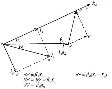
FIG. 24 Relationships between component voltages in a phasor diagram.
Often, however, the power-factor angle q~ at the machine terminals is explicitly known, rather than the angle q~ + 8. It then becomes necessary to locate the quadrature axis and to compute the power angle 8. This can be done with the aid of the construction of FIG. 24.
The phasor diagram of FIG. 23 is repeated by the solid-line phasors in FIG. 24.
Study of this phasor diagram shows that the dashed phasor o'a', perpendicular to ia, equals j iaXq. This result follows geometrically from the fact that triangles o'a'b' and oab are similar because their corresponding sides are perpendicular. Thus:

(Eq. 57)
(Eq. 58)
Thus, line o'a' is the phasor jXqla and the phasor sum f'a + laga a tjlaXq then locates the angular position of the generated voltage J~af (which in turn lies along the quadrature axis) and therefore the direct and quadrature axes. Physically this must be so, because all the field excitation in a normal machine is in the direct axis. Once the quadrature axis (and hence 8) is known, J~af can be found as shown in FIG. 23
(Eq. 59)
One use of these relations in determining the excitation requirements for specified operating conditions at the terminals of a salient-pole machine is illustrated in Example 9.
7. POWER-ANGLE CHARACTERISTICS OF SALIENT-POLE MACHINES
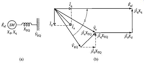
FIG. 26 Salient-pole synchronous machine and series impedance: (a)
single-line diagram and (b) phasor diagram.
For the purposes of this discussion, it is sufficient to limit our discussion to the simple system shown in the schematic diagram of FIG. 26a, consisting of a salient pole synchronous machine SM connected to an infinite bus of voltage f'EQ through a series impedance of reactance XEQ. Resistance will be neglected because it is usually small. Consider that the synchronous machine is acting as a generator. The phasor diagram is shown by the solid-line phasors in FIG. 26b. The dashed phasors show the external reactance drop resolved into components due to id and iq. The effect of the external impedance is merely to add its reactance to the reactances of the machine; the total values of the reactance between the excitation voltage/~af and the bus voltage VEQ is therefore ...
(Eq. 60)
(Eq. 61)
If the bus voltage VEQ is resolved into components its direct-axis component Vd -VEQ sin 6 and quadrature-axis component Vq = VEQ cos ~ in phase with id and iq, respectively, the power P delivered to the bus per phase (or in per unit) is:
(Eq. 62)
(Eq. 63)
(Eq. 64)
Substitution of Eqs. 63 and 64 in Eq. 62 gives
(Eq. 65)
Equation 65 is directly analogous to Eq. 47 which applies to the case of a nonsalient machine. It gives the power per phase when Eaf and VEQ are expressed as line-neutral voltages and the reactances are in ff2/phase, in which case the result must be multiplied by three to get three-phase power. Alternatively, expressing Eaf and VEQ as line-to-line voltages will result in three-phase power directly.
Similarly, Eq. 65 can be applied directly if the various quantities are expressed in per unit.
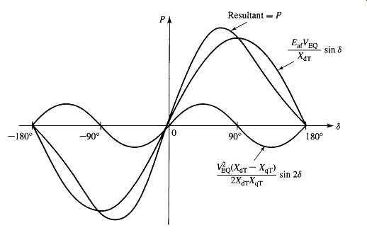
FIG. 27 Power-angle characteristic of a salient-pole synchronous machine
showing the fundamental component due to field excitation and the second-harmonic
component due to reluctance torque.
The general form of this power-angle characteristic is shown in FIG. 27. The first term is the same as the expression obtained for a cylindrical-rotor machine (Eq. 47). The second term includes the effect of salient poles. It represents the fact that the airgap flux wave creates torque, tending to align the field poles in the position of minimum reluctance. This term is the power corresponding to the reluctance torque and is of the same general nature as the reluctance torque discussed in Section 3.5. Note that the reluctance torque is independent of field excitation. Also note that, if XdT = XqT as in a uniform-air-gap machine, there is no preferential direction of magnetization, the reluctance torque is zero and Eq. 65 reduces to the power-angle equation for a cylindrical-rotor machine (Eq. 47). Notice that the characteristic for negative values of 3 is the same except for a reversal in the sign of P. That is, the generator and motor regions are alike if the effects of resistance are negligible. For generator action J~af leads fEe; for motor action/~af lags fEe. Steady-state operation is stable over the range where the slope of the power-angle characteristic is positive. Because of the reluctance torque, a salient-pole machine is "stiffer" than one with a cylindrical rotor; i.e., for equal voltages and equal values of XdT, a salient-pole machine develops a given torque at a smaller value of 3, and the maximum torque which can be developed is somewhat greater.
The effect, as seen in Example 11, of salient poles on the maximum power capability of a synchronous machine increases as the excitation voltage is decreased, as can be seen from Eq. 65. Under typical operating conditions, the effect of salient poles usually amounts to a few percent at most. Only at small excitations does the reluctance torque become important. Thus, except at small excitations or when very accurate results are required, a salient-pole machine usually can be adequately treated by simple cylindrical-rotor theory.
8. PERMANENT-MAGNET AC MOTORS
Permanent-magnet ac motors are polyphase synchronous motors with permanent-magnet rotors. Thus they are similar to the synchronous machines discussed up to this point in this section with the exception that the field windings are replaced by permanent magnets.
FIG. 29 is a schematic diagram of a three-phase permanent-magnet ac machine. Comparison of this figure with FIG. 2 emphasizes the similarities between the permanent-magnet ac machine and the conventional synchronous machine. In fact, the permanent-magnet ac machine can be readily analyzed with the techniques of this section simply by assuming that the machine is excited by a field current of constant value, making sure to calculate the various machine inductances based on the effective permeability of the permanent-magnet rotor.
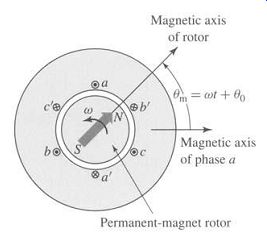
FIG. 29 Schematic diagram of a three-phase permanent-magnet ac machine.
The arrow indicates the direction of rotor magnetization.
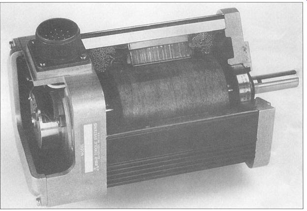
FIG. 30 Cutaway view of a permanent-magnet ac motor. Also shown is
the shaft speed and position sensor used to control the motor. (EG&G
Torque Systems.)
FIG. 30 shows a cutaway view of a typical permanent-magnet ac motor.
This figure also shows a speed and position sensor mounted on the rotor shaft. This sensor is used for control of the motor, as is discussed in Section 11.2. A number of techniques may be used for shaft-position sensing, including Hall-effect devices, light-emitting diodes and phototransistors in combination with a pulsed wheel, and inductance pickups.
Permanent-magnet ac motors are typically operated from variable-frequency motor drives. Under conditions of constant-frequency, sinusoidal polyphase excitation, a permanent-magnet ac motor behaves similarly to a conventional ac synchronous machine with constant field excitation.
An alternate viewpoint of a permanent-magnet ac motor is that it is a form of permanent-magnet stepping motor with a nonsalient stator (see Section 8.5). Under this viewpoint, the only difference between the two is that there will be little, if any, saliency (cogging) torque in the permanent-magnet ac motor. In the simplest operation, the phases can be simply excited with stepped waveforms so as to cause the rotor to step sequentially from one equilibrium position to the next. Alternatively, using rotor-position feedback from a shaft-position sensor, the motor phase windings can be continuously excited in such a fashion as to control the torque and speed of the motor.
As with the stepping motor, the frequency of the excitation determines the motor speed, and the angular position between the rotor magnetic axis and a given phase and the level of excitation in that phase determines the torque which will be produced.
Permanent-magnet ac motors are frequently referred to as brushless motors or brushless dc motors. This terminology comes about both because of the similarity, when combined with a variable-frequency, variable-voltage drive system, of their speed-torque characteristics to those of dc motors and because of the fact that one can view these motors as inside-out dc motors, with their field winding on the rotor and with their armature electronically commutated by the shaft-position sensor and by switches connected to the armature windings.
9. SUMMARY
Under steady-state operating conditions, the physical picture of the operation of a polyphase synchronous machine is simply seen in terms of the interaction of two magnetic fields as discussed in Section 4.7.2. Polyphase currents on the stator produce a rotating magnetic flux wave while dc currents on the rotor produce a flux wave which is stationary with respect to the rotor. Constant torque is produced only when the rotor rotates in synchronism with the stator flux wave. Under these conditions, there is a constant angular displacement between the rotor and stator flux waves and the result is a torque which is proportional to the sine of the displacement angle.
We have seen that a simple set of tests can be used to determine the significant parameters of a synchronous machine including the synchronous reactance Xs or Xd. Two such tests are an open-circuit test, in which the machine terminal voltage is measured as a function of field current, and a short-circuit test, in which the armature is short-circuited and the short-circuit armature current is measured as a function of field current. These test methods are a variation of a testing technique applicable not only to synchronous machines but also to any electrical system whose behavior can be approximated by a linear equivalent circuit to which Thevenin's theorem applies. From a Thevenin-theorem viewpoint, an open-circuit test gives the intemal voltage, and a short-circuit test gives information regarding the internal impedance. From the more specific viewpoint of electromechanical machinery, an open-circuit test gives information regarding excitation requirements, core losses, and (for rotating machines) friction and windage losses; a short-circuit test gives information regarding the magnetic reactions of the load current, leakage impedances, and losses associated with the load current such as I^2R and stray load losses. The only real complication arises from the effects of magnetic nonlinearity, effects which can be taken into account approximately by considering the machine to be equivalent to an unsaturated one whose magnetization curve is the straight line Op of FIG. 9 and whose synchronous reactance is empirically adjusted for saturation as in Eq. 29.
In many cases, synchronous machines are operated in conjunction with an external system which can be represented as a constant-frequency, constant-voltage source known as an infinite bus. Under these conditions, the synchronous speed is determined by the frequency of the infinite bus, and the machine output power is proportional to the product of the bus voltage, the machine internal voltage (which is, in turn, proportional to the field excitation), and the sine of the phase angle between them (the power angle), and it is inversely proportional to the net reactance between them.
While the real power at the machine terminals is determined by the shaft power input to the machine (if it is acting as a generator) or the shaft load (if it is a motor), varying the field excitation varies the reactive power. For low values of field current, the machine will absorb reactive power from the system and the power angle will be large. Increasing the field current will reduce the reactive power absorbed by the machine as well as the power angle. At some value of field current, the machine power factor will be unity and any further increase in field current will cause the machine to supply reactive power to the system.
Once brought up to synchronous speed, synchronous motors can be operated quite efficiently when connected to a constant-frequency source. However, as we have seen, a synchronous motor develops torque only at synchronous speed and hence has no starting torque. To make a synchronous motor self-starting, a squirrel-cage winding, called an amortisseur or damper winding, can be inserted in the rotor pole faces, as shown in FIG. 31. The rotor then comes up almost to synchronous speed by induction-motor action with the field winding unexcited. If the load and inertia are not too great, the motor will pull into synchronism when the field winding is energized from a dc source.
Alternatively, as we will see in Section 11, synchronous motors can be operated from polyphase variable-frequency drive systems. In this case they can be easily started and operated quite flexibly. Small permanent-magnet synchronous machines operated under such conditions are frequently referred to as brushless motors or brushless-dc motors, both because of the similarity of their speed-torque characteristics to those of dc motors and because of the fact that one can view these motors as inside-out dc motors, with the commutation of the stator windings produced electronically by the drive electronics.
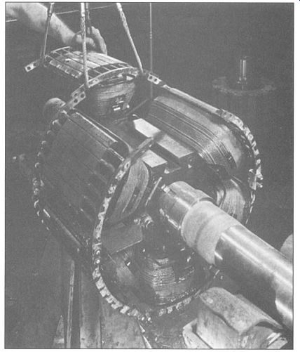
FIG. 31 Rotor of a six-pole 1200 r/min synchronous motor showing field
coils, pole-face damper winding, and construction.
10. PROBLEMS
1. The full-load torque angle of a synchronous motor at rated voltage and frequency is 35 electrical degrees. Neglect the effects of armature resistance and leakage reactance. If the field current is held constant, how would the full-load torque angle be affected by the following changes in operating condition?
a. Frequency reduced 10 percent, load torque and applied voltage constant.
b. Frequency reduced 10 percent, load power and applied voltage constant.
c. Both frequency and applied voltage reduced 10 percent, load torque constant.
d. Both frequency and applied voltage reduced 10 percent, load power constant.
2 The armature phase windings of a two-phase synchronous machine are displaced by 90 electrical degrees in space.
a. What is the mutual inductance between these two windings?
b. Repeat the derivation leading to Eq. 17 and show that the synchronous inductance is simply equal to the armature phase inductance; that is, Ls = Laa0 -kLal, where Laa0 is the component of the armature phase inductance due to space-fundamental air-gap flux and Lal is the armature leakage inductance.
3 Design calculations show the following parameters for a three-phase, cylindrical-rotor synchronous generator: Phase-a self-inductance Laa -4.83 mH Armature leakage inductance Lal = 0.33 mH Calculate the phase-phase mutual inductance and the machine synchronous inductance.
4 The open-circuit terminal voltage of a three-phase, 60-Hz synchronous generator is found to be 15.4 kV rms line-to-line when the field current is 420 A.
a. Calculate the stator-to-rotor mutual inductance Laf.
b. Calculate the open-circuit terminal voltage if the field current is held constant while the generator speed is reduced so that the frequency of the generated voltage is 50 Hz.
5 A 460-V, 50-kW, 60-Hz, three-phase synchronous motor has a synchronous reactance of Xs = 4.15 f2 and an armature-to-field mutual inductance, Laf -83 mH. The motor is operating at rated terminal voltage and an input power of 40 kW. Calculate the magnitude and phase angle of the line-to-neutral generated voltage/~af and the field current If if the motor is operating at (a) 0.85 power factor lagging, (b) unity power factor, and (c) 0.85 power factor leading.
6 The motor of Problem 5 is supplied from a 460-V, three-phase source through a feeder whose impedance is Zf = 0.084 + j0.82 f2. Assuming the system (as measured at the source) to be operating at an input power of 40 kW, calculate the magnitude and phase angle of the line-to-neutral generated voltage/~af and the field current If for power factors of (a) 0.85 lagging, (b) unity, and (c) 0.85 leading.
7 A 50-Hz, two-pole, 750 kVA, 2300 V, three-phase synchronous machine has a synchronous reactance of 7.75 f2 and achieves rated open-circuit terminal voltage at a field current of 120 A.
a. Calculate the armature-to-field mutual inductance.
b. The machine is to be operated as a motor supplying a 600 kW load at its rated terminal voltage. Calculate the internal voltage Eaf and the corresponding field current if the motor is operating at unity power factor.
c. For a constant load power of 600 kW, write a MATLAB script to plot the terminal current as a function of field current. For your plot, let the field current vary between a minimum value corresponding to a machine loading of 750 kVA at leading power factor and a maximum value corresponding to a machine loading of 750 kVA at lagging power factor.
What value of field current produces the minimum terminal current? Why?
8 The manufacturer's data sheet for a 26-kV, 750-MVA, 60-Hz, three-phase synchronous generator indicates that it has a synchronous reactance Xs -2.04 and a leakage reactance Xal = 0.18, both in per unit on the generator base. Calculate (a) the synchronous inductance in mH, (b) the armature leakage inductance in mH, and (c) the armature phase inductance Laa in mH and per unit.
9 The following readings are taken from the results of an open- and a shortcircuit test on an 800-MVA, three-phase, Y-connected, 26-kV, two-pole, 60-Hz turbine generator driven at synchronous speed: Field current, A Armature current, short-circuit test, kA Line voltage, open-circuit characteristic, kV Line voltage, air-gap line, kV 1540 2960 9.26 17.8 26.0 (31.8)
29.6 (56.9)
The number in parentheses are extrapolations based upon the measured data.
Find (a) the short-circuit ratio, (b) the unsaturated value of the synchronous reactance in ohms per phase and per unit, and (c) the saturated synchronous reactance in per unit and in ohms per phase.
10 The following readings are taken from the results of an open- and a short-circuit test on a 5000-kW, 4160-V, three-phase, four-pole, 1800-rpm synchronous motor driven at rated speed:
Field current, A 169 192 Armature current, short-circuit test, A 694 790 Line voltage, open-circuit characteristic, V 3920 4160 Line voltage, air-gap line, V 4640 5270.
The armature resistance is 11 mf^2/phase. The armature leakage reactance is estimated to be 0.12 per unit on the motor rating as base. Find (a) the short-circuit ratio, (b) the unsaturated value of the synchronous reactance in ohms per phase and per unit, and (c) the saturated synchronous reactance in per unit and in ohms per phase.
11 Write a MATLAB script which automates the calculations of Problems 9 and 10. The following minimum set of data is required: II AFNL: The field current required to achieve rated open-circuit terminal voltage.
II The corresponding terminal voltage on the air gap line.
II AFSC: The field current required to achieve rated short-circuit current on the short-circuit characteristic.
Your script should calculate (a) the short-circuit ratio, (b) the unsaturated value of the synchronous reactance in ohms per phase and per unit, and (c) the saturated synchronous reactance in per unit and in ohms per phase.
12 Consider the motor of Problem 10.
a. Compute the field current required when the motor is operating at rated voltage, 4200 kW input power at 0.87 power factor leading. Account for saturation under load by the method described in the paragraph relating to Eq. 29.
b. In addition to the data given in Problem 5.10, additional points on the open-circuit characteristic are given below:
Field current, A 200 250 300 350 Line voltage, V 4250 4580 4820 5000
If the circuit breaker supplying the motor of part (a) is tripped, leaving the motor suddenly open-circuited, estimate the value of the motor terminal voltage following the trip (before the motor begins to slow down and before any protection circuitry reduces the field current).
13 Using MATLAB, plot the field current required to achieve unity-power-factor operation for the motor of Problem 5.10 as the motor load varies from zero to full load. Assume the motor to be operating at rated terminal voltage.
14 Loss data for the motor of Problem 10 are as follows: Open-circuit core loss at 4160 V = 37 kW Friction and windage loss = 46 kW Field-winding resistance at 75°C = 0.279 f2 Compute the output power and efficiency when the motor is operating at rated input power, unity power factor, and rated voltage. Assume the field-winding to be operating at a temperature of 125°C. 5.15 The following data are obtained from tests on a 145-MVA, 13.8-kV, three phase, 60-Hz, 72-pole hydroelectric generator.
Open-circuit characteristic:
If, A 100 200 300 400 500 600 700 775 800
Voltage, kV 2.27 4.44 6.68 8.67 10.4 11.9 13.4 14.3 14.5 Short-circuit test:
If = 710 A, la = 6070 A
a. Draw (or plot using MATLAB) the open-circuit saturation curve, the air-gap line, and the short-circuit characteristic.
b. Find AFNL and AFSC. (Note that if you use MATLAB for part (a), you can use the MATLAB function 'polyfit' to fit a second-order polynomial to the open-circuit saturation curve. You can then use this fit to find AFNL.)
c. Find (i) the short-circuit ratio, (ii) the unsaturated value of the synchronous reactance in ohms per phase and per unit and (iii) the saturated synchronous reactance in per unit and in ohms per phase.
16 What is the maximum per-unit reactive power that can be supplied by a synchronous machine operating at its rated terminal voltage whose synchronous reactance is 1.6 per unit and whose maximum field current is limited to 2.4 times that required to achieve rated terminal voltage under open-circuit conditions?
17 A 25-MVA, 11.5 kV synchronous machine is operating as a synchronous condenser, as discussed in Section D (section D.4.1). The generator short-circuit ratio is 1.68 and the field current at rated voltage, no load is 420 A. Assume the generator to be connected directly to an 11.5 kV source.
a. What is the saturated synchronous reactance of the generator in per unit and in ohms per phase? The generator field current is adjusted to 150 A.
b. Draw a phasor diagram, indicating the terminal voltage, internal voltage, and armature current.
c. Calculate the armature current magnitude (per unit and amperes) and its relative phase angle with respect to the terminal voltage.
d. Under these conditions, does the synchronous condenser appear inductive or capacitive to the 11.5 kV system?
e. Repeat parts (b) through (d) for a field current of 700 A. 5.18 The synchronous condenser of Problem 17 is connected to a 11.5 kV system through a feeder whose series reactance is 0.12 per unit on the machine base.
Using MATLAB, plot the voltage (kV) at the synchronous-condenser terminals as the synchronous-condenser field current is varied between 150 A and 700 A. 5.19 A synchronous machine with a synchronous reactance of 1.28 per unit is operating as a generator at a real power loading of 0.6 per unit connected to a system with a series reactance of 0.07 per unit. An increase in its field current is observed to cause a decrease in armature current.
a. Before the increase, was the generator supplying or absorbing reactive power from the power system?
b. As a result of this increase in excitation, did the generator terminal voltage increase or decrease?
c. Repeat parts (a) and (b) if the synchronous machine is operating as a motor.
20 Superconducting synchronous machines are designed with superconducting fields windings which can support large current densities and create large magnetic flux densities. Since typical operating magnetic flux densities exceed the saturation flux densities of iron, these machines are typically designed without iron in the magnetic circuit; as a result, these machines exhibit no saturation effects and have low synchronous reactances.
Consider a two-pole, 60-Hz, 13.8-kV, 10-MVA superconducting generator which achieves rated open-circuit armature voltage at a field current of 842 A. It achieves rated armature current into a three-phase terminal short circuit for a field current of 226 A.
a. Calculate the per-unit synchronous reactance.
Consider the situation in which this generator is connected to a 13.8 kV distribution feeder of negligible impedance and operating at an output power of 8.75 MW at 0.9 pf lagging. Calculate:
b. the field current in amperes, the reactive-power output in MVA, and the rotor angle for this operating condition.
c. the resultant rotor angle and reactive-power output in MVA if the field current is reduced to 842 A while the shaft-power supplied by the prime mover to the generator remains constant.
21 For a synchronous machine with constant synchronous reactance Xs operating at a constant terminal voltage Vt and a constant excitation voltage Eaf, show that the locus of the tip of the armature-current phasor is a circle. On a phasor diagram with terminal voltage shown as the reference phasor, indicate the position of the center of this circle and its radius. Express the coordinates of the center and the radius of the circle in terms of Vt, Eaf and Xs.
22 A four-pole, 60-Hz, 24-kV, 650-MVA synchronous generator with a synchronous reactance of 1.82 per unit is operating on a power system which can be represented by a 24-kV infinite bus in series with a reactive impedance of j0.21 f2. The generator is equipped with a voltage regulator that adjusts the field excitation such that the generator terminal voltage remains at 24 kV independent of the generator loading.
a. The generator output power is adjusted to 375 MW. (i) Draw a phasor diagram for this operating condition.
(ii) Find the magnitude (in kA) and phase angle (with respect to the generator terminal voltage) of the terminal current.
(iii) Determine the generator terminal power factor.
(iv) Find the magnitude (in per unit and kV) of the generator excitation voltage Eaf.
b. Repeat part (a) if the generator output power is increased to 600 MW.
23 The generator of Problem 22 achieves rated open-circuit armature voltage at a field current of 850 A.
It is operating on the system of Problem 22 with its voltage regulator set to maintain the terminal voltage at 0.99 per unit (23.8 kV).
a. Use MATLAB to plot the generator field current (in A) as a function of load (in MW) as the load on the generator output power is varied from zero to full load.
b. Plot the corresponding reactive output power in MVAR as a function of output load.
c. Repeat the plots of parts (a) and (b) if the voltage regulator is set to regulate the terminal voltage to 1.01 per unit (24.2 kV).
24 The 145 MW hydroelectric generator of Problem 15 is operating on a 13.8-kV power system. Under normal operating procedures, the generator is operated under automatic voltage regulation set to maintain its terminal voltage at 13.8 kV. In this problem you will investigate the possible consequences should the operator forget to switch over to the automatic voltage regulator and instead leave the field excitation constant at AFNL, the value corresponding to rated open-circuit voltage. For the purposes of this problem, neglect the effects of saliency and assume that the generator can be represented by the saturated synchronous reactance found in Problem 15.
a. If the power system is represented simply by a 13.8 kV infinite (ignoring the effects of any equivalent impedance), can the generator be loaded to full load? If so, what is the power angle 3 corresponding to full load? If not, what is the maximum load that can be achieved?
b. Repeat part (a) with the power system now represented by a 13.8 kV infinite bus in series with a reactive impedance of j0.14 f^2.
25 Repeat Example 9 assuming the generator is operating at one-half of its rated kVA at a lagging power factor of 0.8 and rated terminal voltage.
26 Repeat Problem 24 assuming that the saturated direct-axis synchronous inductance Xd is equal to that found in Problem 15 and that the saturated quadrature-axis synchronous reactance Xq is equal to 75 percent of this value.
Compare your answers to those found in Problem 24.
27 Write a MATLAB script to plot a set of per-unit power-angle curves for a salient-pole synchronous generator connected to an infinite bus (Vbus = 1.0 per unit). The generator reactances are Xd = 1.27 per unit and Xq = 0.95 per unit. Assuming Eaf = 1.0 per unit, plot the following curves:
a. Generator connected directly to the infinite bus.
b. Generator connected to the infinite bus through a reactance Xbus --0.1 per unit.
c. Generator connected directly to the infinite bus. Neglect saliency effects, setting Xq -X d.
d. Generator connected to the infinite bus through a reactance Xbus =
0.1 per unit. Neglect saliency effects, setting Xq -Xd.
28 Draw the steady-state, direct- and quadrature-axis phasor diagram for a salient-pole synchronous motor with reactances Xd and Xq and armature resistance Ra. From this phasor diagram, show that the torque angle 8 between the generated voltage J~af (which lies along the quadrature axis) and the terminal voltage l)t is given by:
tan ~ IaXq COS t~ + Ia Ra sin ~b / Vt + IaXq sin ~bIaRa cos ~b
Here ¢ is the phase angle of the armature current i~ a and Vt, considered to be negative when i~ a lags ft.
29 Repeat Problem 28 for synchronous generator operation, in which case the equation for 3 becomes tan 6 IaXq COS t~ + la Ra sin ~b Vt IaXq sin ¢ + la Ra cos ~b
30 What maximum percentage of its rated output power will a salient-pole motor deliver without loss of synchronism when operating at its rated terminal voltage with zero field excitation (Eaf "0) if Xd = 0.90 per unit and Xq -0.65 per unit? Compute the per-unit armature current and reactive power for this operating condition.
31 If the synchronous motor of Problem 30 is now operated as a synchronous generator connected to an infinite bus of rated voltage, find the minimum per-unit field excitation (where 1.0 per unit is the field current required to achieve rated open-circuit voltage) for which the generator will remain synchronized at (a) half load and (b) full load.
32 A salient-pole synchronous generator with saturated synchronous reactances Xo -1.57 per unit and Xq = 1.34 per unit is connected to an infinite bus of rated voltage through an external impedance Xbus -0.11 per unit. The generator is supplying its rated MVA at 0.95 power factor lagging, as measured at the generator terminals.
a. Draw a phasor diagram, indicating the infinite-bus voltage, the armature current, the generator terminal voltage, the excitation voltage, and the rotor angle (measured with respect to the infinite bus).
b. Calculate the per-unit terminal and excitation voltages, and the rotor angle in degrees.
33 A salient-pole synchronous generator with saturated synchronous reactances Xd = 0.78 per unit and Xq = 0.63 per unit is connected to a rated-voltage infinite bus through an external impedance Xbus = 0.09 per unit.
a. Assuming the generator to be supplying only reactive power (i) Find minimum and maximum per-unit field excitations (where 1.0 per unit is the field current required to achieve rated open-circuit voltage) such that the generator does not exceed its rated terminal current.
(ii) Using MATLAB, plot the armature current as a function of field excitation as the field excitation is varied between the limits determined in part (i).
b. Now assuming the generator to be supplying 0.25 per unit rated real power, on the same axes add a plot of the per-unit armature current as a function of field excitation as the field current is varied in the range for which the per-unit armature current is less than 1.0 per unit.
c. Repeat part (b) for generator output powers of 0.50 and 0.75 per unit.
The final result will be a plot of V-curves for this generator in this configuration.
34 A two-phase permanent-magnet ac motor has a rated speed of 3000 r/min and a six-pole rotor. Calculate the frequency (in Hz) of the armature voltage required to operate at this speed.
35 A 5-kW, three-phase, permanent-magnet synchronous generator produces an open-circuit voltage of 208 V line-to-line, 60-Hz, when driven at a speed of 1800 r/min. When operating at rated speed and supplying a resistive load, its terminal voltage is observed to be 192 V line-to-line for a power output of 4.5 kW.
a. Calculate the generator phase current under this operating condition.
b. Assuming the generator armature resistance to be negligible, calculate the generator 60-Hz synchronous reactance.
c. Calculate the generator terminal voltage which will result if the motor generator load is increased to 5 kW (again purely resistive) while the speed is maintained at 1800 r/min.
36. Small single-phase permanent-magnet ac generators are frequently used to generate the power for lights on bicycles. For this application, these generators are typically designed with a significant amount of leakage inductance in their armature winding. A simple model for these generators is an ac voltage source e_a(t) = ωKa cos cot in series with the armature leakage inductance La and the armature resistance Ra. Here co is the electrical frequency of the generated voltage which is determined by the speed of the generator as it rubs against the bicycle wheel.
Assuming that the generator is running a light bulb which can be modeled as a resistance Rb, write an expression for the minimum frequency ω min which must be achieved in order to insure that the light operates at constant brightness, independent of the speed of the bicycle.