AMAZON multi-meters discounts AMAZON oscilloscope discounts
The objective of this guide is to study the devices used in the inter-conversion of electric and mechanical energy. Emphasis is placed on electromagnetic rotating machinery, by means of which the bulk of this energy conversion takes place. However, the techniques developed are generally applicable to a wide range of additional devices including linear machines, actuators, and sensors.
Although not an electromechanical-energy-conversion device, the transformer is an important component of the overall energy-conversion process and is discussed in Section 2. The techniques developed for transformer analysis form the basis for the ensuing discussion of electric machinery.
Practically all transformers and electric machinery use ferro-magnetic material for shaping and directing the magnetic fields which act as the medium for transferring and converting energy. Permanent-magnet materials are also widely used. Without these materials, practical implementations of most familiar electromechanical-energy-conversion devices would not be possible. The ability to analyze and describe systems containing these materials is essential for designing and understanding these devices.
This section will develop some basic tools for the analysis of magnetic field systems and will provide a brief introduction to the properties of practical magnetic materials. In Section 2, these results will then be applied to the analysis of transformers. In later sections they will be used in the analysis of rotating machinery.
In this guide it is assumed that the reader has basic knowledge of magnetic and electric field theory such as given in a basic physics course for engineering students. Some readers may have had a course on electromagnetic field theory based on Maxwell's equations, but an in-depth understanding of Maxwell's equations is not a prerequisite for study of this guide. The techniques of magnetic-circuit analysis, which represent algebraic approximations to exact field-theory solutions, are widely used in the study of electromechanical-energy-conversion devices and form the basis for most of the analyses presented here.
1. INTRODUCTION TO MAGNETIC CIRCUITS
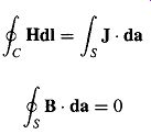
The complete, detailed solution for magnetic fields in most situations of practical engineering interest involves the solution of Maxwell's equations along with various constitutive relationships which describe material properties. Although in practice exact solutions are often unattainable, various simplifying assumptions permit the attainment of useful engineering solutions. We begin with the assumption that, for the systems treated in this guide, the frequencies and sizes involved are such that the displacement-current term in Maxwell's equations can be neglected. This term accounts for magnetic fields being produced in space by time-varying electric fields and is associated with electromagnetic radiation. Neglecting this term results in the magneto-quasistatic form of the relevant Maxwell's equations which relate magnetic fields to the currents which produce them.
(Eqn. 1)
(Eqn. 2)
Equation 1 states that the line integral of the tangential component of the magnetic field intensity H around a closed contour C is equal to the total current passing through any surface S linking that contour. From Eq. 1 we see that the source of H is the current density J. Equation 2 states that the magnetic flux density B is conserved, i.e., that no net flux enters or leaves a closed surface (this is equivalent to saying that there exist no monopole charge sources of magnetic fields). From these equations we see that the magnetic field quantities can be determined solely from the instantaneous values of the source currents and that time variations of the magnetic fields follow directly from time variations of the sources.
A second simplifying assumption involves the concept of the magnetic circuit. The general solution for the magnetic field intensity H and the magnetic flux density B in a structure of complex geometry is extremely difficult. However, a three-dimensional field problem can often be reduced to what is essentially a one-dimensional circuit equivalent, yielding solutions of acceptable engineering accuracy.
A magnetic circuit consists of a structure composed for the most part of high-permeability magnetic material. The presence of high-permeability material tends to cause magnetic flux to be confined to the paths defined by the structure, much as currents are confined to the conductors of an electric circuit. Use of this concept of the magnetic circuit is illustrated in this section and will be seen to apply quite well to many situations in this guide.
[Although exact analytical solutions cannot be obtained, computer-based numerical solutions (the finite-element and boundary-element methods form the basis for a number of commercial programs) are quite common and have become indispensible tools for analysis and design. However, such techniques are best used to refine analyses based upon analytical techniques such as are found in this guide. Their use contributes little to a fundamental understanding of the principles and basic performance of electric machines and as a result they will not be discussed in this guide. ]
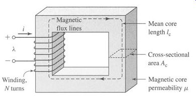
FIG. 1 Simple magnetic circuit.
A simple example of a magnetic circuit is shown in Fig. 1. The core is assumed to be composed of magnetic material whose permeability is much greater than that of the surrounding air (/z >>/z0). The core is of uniform cross section and is excited by a winding of N turns carrying a current of i amperes. This winding produces a magnetic field in the core, as shown in the figure.
Because of the high permeability of the magnetic core, an exact solution would show that the magnetic flux is confined almost entirely to the core, the field lines follow the path defined by the core, and the flux density is essentially uniform over a cross section because the cross-sectional area is uniform. The magnetic field can be visualized in terms of flux lines which form closed loops interlinked with the winding.
As applied to the magnetic circuit of Fig. 1, the source of the magnetic field in the core is the ampere-turn product Ni. In magnetic circuit terminology N i is the magnetomotive force (mmf) . T" acting on the magnetic circuit. Although Fig. 1 shows only a single coil, transformers and most rotating machines have at least two windings, and N i must be replaced by the algebraic sum of the ampere-turns of all the windings.
The magnetic flux ¢ crossing a surface S is the surface integral of the normal component of B; thus

(Eqn. 3)
In SI units, the unit of Phi is the weber (Wb).
Equation 2 states that the net magnetic flux entering or leaving a closed surface (equal to the surface integral of B over that closed surface) is zero. This is equivalent to saying that all the flux which enters the surface enclosing a volume must leave that volume over some other portion of that surface because magnetic flux lines form closed loops.
These facts can be used to justify the assumption that the magnetic flux density is uniform across the cross section of a magnetic circuit such as the core of Fig. 1.
In this case Eq. 3 reduces to the simple scalar equation

~bc = Bc Ac (Eqn. 4)
where 4)c = flux in core
Bc = flux density in core
Ac = cross-sectional area of core
From Eq. 1, the relationship between the mmf acting on a magnetic circuit and the magnetic field intensity in that circuit is. 3
[3. general, the mmf drop across any segment of a magnetic circuit can be calculated as f I-Idl over In that portion of the magnetic circuit. ]

-Ni -/ Hdl (Eqn. 5)
The core dimensions are such that the path length of any flux line is close to the mean core length lc. As a result, the line integral of Eq. 5 becomes simply the scalar product Hclc of the magnitude of H and the mean flux path length Ic. Thus, the relationship between the mmf and the magnetic field intensity can be written in magnetic circuit terminology as
= Ni -Hclc (Eqn. 6)
where Hc is average magnitude of H in the core.
The direction of Hc in the core can be found from the right-hand rule, which can be stated in two equivalent ways. (1) Imagine a current-carrying conductor held in the right hand with the thumb pointing in the direction of current flow; the fingers then point in the direction of the magnetic field created by that current. (2) Equivalently, if the coil in Fig. 1 is grasped in the right hand (figuratively speaking) with the fingers pointing in the direction of the current, the thumb will point in the direction of the magnetic fields.
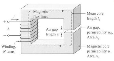
FIG. 2 Magnetic circuit with air gap.
The relationship between the magnetic field intensity H and the magnetic flux density B is a property of the material in which the field exists. It is common to assume a linear relationship; thus B = #H (Eqn. 7)
where # is known as the magnetic permeability. In SI units, H is measured in units of amperes per meter, B is in webers per square meter, also known as teslas (T), and/z is in webers per ampere-turn-meter, or equivalently henrys per meter. In SI units the permeability of free space is #0 = 4:r × 10 ^-7 henrys per meter. The permeability of linear magnetic material can be expressed in terms of/Zr, its value relative to that of free space, or # = #r#0. Typical values of/Z r range from 2000 to 80,000 for materials used in transformers and rotating machines. The characteristics of ferromagnetic materials are described in Sections 3 and 4. For the present we assume that/Zr is a known constant, although it actually varies appreciably with the magnitude of the magnetic flux density.
Transformers are wound on closed cores like that of Fig. 1. However, energy conversion devices which incorporate a moving element must have air gaps in their magnetic circuits. A magnetic circuit with an air gap is shown in Fig. 2. When the air-gap length g is much smaller than the dimensions of the adjacent core faces, the magnetic flux ~ will follow the path defined by the core and the air gap and the techniques of magnetic-circuit analysis can be used. If the air-gap length becomes excessively large, the flux will be observed to "leak out" of the sides of the air gap and the techniques of magnetic-circuit analysis will no longer be strictly applicable.
Thus, provided the air-gap length g is sufficiently small, the configuration of Fig. 2 can be analyzed as a magnetic circuit with two series components: a magnetic core of permeability/~, cross-sectional area Ac, and mean length/c, and an air gap of permeability/z0, cross-sectional area Ag, and length g. In the core the flux density can be assumed uniform; thus
(Eqn. 8)
Ac and in the air gap
(Eqn. 9)
where 4~ = the flux in the magnetic circuit.
Application of Eq. 5 to this magnetic circuit yields
[…]
and using the linear B-H relationship of Eq. 7 gives
(Eqn. 10)
(Eqn. 11)
Here the ~" = Ni is the mmf applied to the magnetic circuit. From Eq. 10 we see that a portion of the mmf, .Tc = Hclc, is required to produce magnetic field in the core while the remainder, fg = Hgg, produces magnetic field in the air gap.
For practical magnetic materials (as is discussed in Sections 1.3 and 1.4), Bc and Hc are not simply related by a known constant permeability/z as described by Eq. 7. In fact, Bc is often a nonlinear, multi-valued function of Hc. Thus, although Eq. 10 continues to hold, it does not lead directly to a simple expression relating the mmf and the flux densities, such as that of Eq. 11. Instead the specifics of the nonlinear Bc-He relation must be used, either graphically or analytically. However, in many cases, the concept of constant material permeability gives results of acceptable engineering accuracy and is frequently used.
From Eqs. 1.8 and 1.9, Eq. 11 can be rewritten in terms of the total flux ~b as

(Eqn. 12)
(Eqn. 13)
(Eqn. 14)
(Eqn. 15)
(Eqn. 16)
(Eqn. 17)
(Eqn. 18)
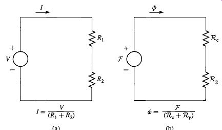
FIG. 3 Analogy between electric and magnetic circuits. (a) Electric circuit,
(b) magnetic circuit.
The term which multiplies the mmfis known as the permeance 7 -9 and is the inverse of the reluctance; thus, for example, the total permeance of a magnetic circuit is
(Eqn. 19)
Note that Eqs. 1.15 and 1.16 are analogous to the relationships between the current and voltage in an electric circuit. This analogy is illustrated in Fig. 3. FIG. 3a shows an electric circuit in which a voltage V drives a current I through resistors R1 and R2. FIG. 3b shows the schematic equivalent representation of the magnetic circuit of Fig. 2. Here we see that the mmf ~ (analogous to voltage in the electric circuit) drives a flux ¢ (analogous to the current in the electric circuit) through the combination of the reluctances of the core 7~c and the air gap ~g. This analogy between the solution of electric and magnetic circuits can often be exploited to produce simple solutions for the fluxes in magnetic °circuits of considerable complexity.
The fraction of the mmf required to drive flux through each portion of the magnetic circuit, commonly referred to as the mmf drop across that portion of the magnetic circuit, varies in proportion to its reluctance (directly analogous to the voltage drop across a resistive element in an electric circuit). From Eq. 13 we see that high material permeability can result in low core reluctance, which can often be made much smaller than that of the air gap; i.e., for
[…]. In this case, the reluctance of the core can be neglected and the flux and hence B can be found from Eq. 16 in terms of f and the air-gap properties alone:

(Eqn. 20)
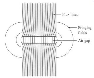
FIG. 4 Air-gap fringing fields.
As will be seen in Section 1.3, practical magnetic materials have permeabilities which are not constant but vary with the flux level. From Eqs. 13 to 16 we see that as long as this permeability remains sufficiently large, its variation will not significantly affect the performance of the magnetic circuit.
In practical systems, the magnetic field lines "fringe" outward somewhat as they cross the air gap, as illustrated in Fig. 4. Provided this fringing effect is not excessive, the magnetic-circuit concept remains applicable. The effect of these fringing fields is to increase the effective cross-sectional area Ag of the air gap. Various empirical methods have been developed to account for this effect. A correction for such fringing fields in short air gaps can be made by adding the gap length to each of the two dimensions making up its cross-sectional area. In this guide the effect of fringing fields is usually ignored. If fringing is neglected, Ag = Ac.
In general, magnetic circuits can consist of multiple elements in series and parallel. To complete the analogy between electric and magnetic circuits, we can generalize Eq. 5 as

(Eqn. 21)
... where .T" is the mmf (total ampere-turns) acting to drive flux through a closed loop of a magnetic circuit,
(Eqn. 22)
and 3ok = Hklk is the mmf drop across the k'th element of that loop. This is directly analogous to Kirchoff's voltage law for electric circuits consisting of voltage sources and resistors
(Eqn. 23)
... where V is the source voltage driving current around a loop and Rkik is the voltage drop across the k'th resistive element of that loop.
Similarly, the analogy to Kirchoff's current law
(Eqn. 24)
n which says that the sum of currents into a node in an electric circuit equals zero is
(Eqn. 25)
... which states that the sum of the flux into a node in a magnetic circuit is zero.
We have now described the basic principles for reducing a magneto-quasistatic field problem with simple geometry to a magnetic circuit model. Our limited purpose in this section is to introduce some of the concepts and terminology used by engineers in solving practical design problems. We must emphasize that this type of thinking depends quite heavily on engineering judgment and intuition. For example, we have tacitly assumed that the permeability of the "iron" parts of the magnetic circuit is a constant known quantity, although this is not true in general, and that the magnetic field is confined only to the core and its air gaps.
Although this is a good assumption in many situations, it is also true that the winding currents produce magnetic fields outside the core. As we shall see, when two or more windings are placed on a magnetic circuit, as happens in the case of both transformers and rotating machines, these fields outside the core, which are referred to as leakage fields, cannot be ignored and significantly affect the performance of the device.
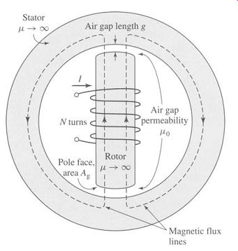
FIG. 5 Simple synchronous machine.
2. FLUX LINKAGE, INDUCTANCE, AND ENERGY
When a magnetic field varies with time, an electric field is produced in space as determined by Faraday's law:
(Eqn. 26)
Equation 26 states that the line integral of the electric field intensity E around a closed contour C is equal to the time rate of change of the magnetic flux linking (i.e.
passing through) that contour. In magnetic structures with windings of high electrical conductivity, such as in Fig. 2, it can be shown that the E field in the wire is extremely small and can be neglected, so that the left-hand side of Eq. 26 reduces to the negative of the induced voltage 4 e at the winding terminals. In addition, the flux on the right-hand side of Eq. 26 is dominated by the core flux 4~. Since the winding (and hence the contour C) links the core flux N times, Eq. 26 reduces to ...
(Eqn. 27)
... where ~. is the flux linkage of the winding and is defined as ...
(Eqn. 28)
Flux linkage is measured in units of webers (or equivalently weber-turns). The symbol q9 is used to indicate the instantaneous value of a time-varying flux.
[The term electromotive force (emf) is often used instead of induced voltage to represent that component of voltage due to a time-varying flux linkage. ]
In general the flux linkage of a coil is equal to the surface integral of the normal component of the magnetic flux density integrated over any surface spanned by that coil. Note that the direction of the induced voltage e is defined by Eq. 26 so that if the winding terminals were short-circuited, a current would flow in such a direction as to oppose the change of flux linkage.
For a magnetic circuit composed of magnetic material of constant magnetic permeability or which includes a dominating air gap, the relationship between q~ and i will be linear and we can define the inductance L as ....
(Eqn. 29)
Substitution of Eqs. 5, 18 and 28 into Eq. 29 gives
(Eqn. 30)
From which we see that the inductance of a winding in a magnetic circuit is proportional to the square of the turns and inversely proportional to the reluctance of the magnetic circuit associated with that winding.
For example, from Eq. 20, under the assumption that the reluctance of the core is negligible as compared to that of the air gap, the inductance of the winding in Fig. 2 is equal to
(Eqn. 31)
Inductance is measured in henrys (H) or weber-turns per ampere. Equation 31 shows the dimensional form of expressions for inductance; inductance is proportional to the square of the number of turns, to a magnetic permeability, and to a cross-sectional area and is inversely proportional to a length. It must be emphasized that, strictly speaking, the concept of inductance requires a linear relationship between flux and mmf. Thus, it cannot be rigorously applied in situations where the nonlinear characteristics of magnetic materials, as is discussed in Sections 3 and 4, dominate the performance of the magnetic system. However, in many situations of practical interest, the reluctance of the system is dominated by that of an air gap (which is of course linear) and the nonlinear effects of the magnetic material can be ignored. In other cases it may be perfectly acceptable to assume an average value of magnetic permeability for the core material and to calculate a corresponding average inductance which can be used for calculations of reasonable engineering accuracy. Example 3 illustrates the former situation and Example 4 the latter.
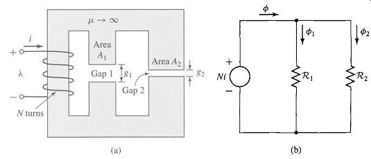
FIG. 6 (a) Magnetic circuit and (b) equivalent circuit for Example 3.
3. PROPERTIES OF MAGNETIC MATERIALS
In the context of electromechanical energy conversion devices, the importance of magnetic materials is twofold. Through their use it is possible to obtain large magnetic flux densities with relatively low levels of magnetizing force. Since magnetic forces and energy density increase with increasing flux density, this effect plays a large role in the performance of energy-conversion devices.
In addition, magnetic materials can be used to constrain and direct magnetic fields in well-defined paths. In a transformer they are used to maximize the coupling between the windings as well as to lower the excitation current required for transformer operation. In electric machinery, magnetic materials are used to shape the fields to obtain desired torque-production and electrical terminal characteristics. Thus a knowledgeable designer can use magnetic materials to achieve specific desirable device characteristics.
Ferromagnetic materials, typically composed of iron and alloys of iron with cobalt, tungsten, nickel, aluminum, and other metals, are by far the most common magnetic materials. Although these materials are characterized by a wide range of properties, the basic phenomena responsible for their properties are common to them all.
Ferromagnetic materials are found to be composed of a large number of domains, i.e., regions in which the magnetic moments of all the atoms are parallel, giving rise to a net magnetic moment for that domain. In an unmagnetized sample of material, the domain magnetic moments are randomly oriented, and the net resulting magnetic flux in the material is zero.
When an external magnetizing force is applied to this material, the domain magnetic moments tend to align with the applied magnetic field. As a result, the domain magnetic moments add to the applied field, producing a much larger value of flux density than would exist due to the magnetizing force alone. Thus the effective permeability lz, equal to the ratio of the total magnetic flux density to the applied magnetic-field intensity, is large compared with the permeability of free space/z0. As the magnetizing force is increased, this behavior continues until all the magnetic moments are aligned with the applied field; at this point they can no longer contribute to increasing the magnetic flux density, and the material is said to be fully saturated.
In the absence of an externally applied magnetizing force, the domain magnetic moments naturally align along certain directions associated with the crystal structure of the domain, known as axes of easy magnetization. Thus if the applied magnetizing force is reduced, the domain magnetic moments relax to the direction of easy magnetism nearest to that of the applied field. As a result, when the applied field is reduced to zero, although they will tend to relax towards their initial orientation, the magnetic dipole moments will no longer be totally random in their orientation; they will retain a net magnetization component along the applied field direction. It is this effect which is responsible for the phenomenon known as magnetic hysteresis.
Due to this hysteresis effect, the relationship between B and H for a ferromagnetic material is both nonlinear and multi-valued. In general, the characteristics of the material cannot be described analytically. They are commonly presented in graphical form as a set of empirically determined curves based on test samples of the material using methods prescribed by the American Society for Testing and Materials (ASTM). 5
[5 Numerical data on a wide variety of magnetic materials are available from material manufacturers. One problem in using such data arises from the various systems of units employed. For example, magnetization may be given in oersteds or in ampere-turns per meter and the magnetic flux density in gauss, kilogauss, or teslas. A few useful conversion factors are given in Section E. The reader is reminded that the equations in this guide are based upon SI units. ]
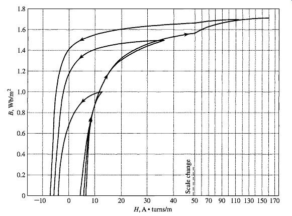
FIG. 9 -- B-H loops for M-5 grain-oriented electrical steel 0.012 in thick.
Only the top halves of the loops are shown here. (Armco Inc.)
The most common curve used to describe a magnetic material is the B-H curve or hysteresis loop. The first and second quadrants (corresponding to B > 0) of a set of hysteresis loops are shown in Fig. 9 for M-5 steel, a typical grain-oriented electrical steel used in electric equipment. These loops show the relationship between the magnetic flux density B and the magnetizing force H. Each curve is obtained while cyclically varying the applied magnetizing force between equal positive and negative values of fixed magnitude. Hysteresis causes these curves to be multi-valued. After several cycles the B-H curves form closed loops as shown. The arrows show the paths followed by B with increasing and decreasing H. Notice that with increasing magnitude of H the curves begin to flatten out as the material tends toward saturation. At a flux density of about 1.7 T, this material can be seen to be heavily saturated.
Notice that as H is decreased from its maximum value to zero, the flux density decreases but not to zero. This is the result of the relaxation of the orientation of the magnetic moments of the domains as described above. The result is that there remains a remanant magnetization when H is zero.
Fortunately, for many engineering applications, it is sufficient to describe the material by a single-valued curve obtained by plotting the locus of the maximum values of B and H at the tips of the hysteresis loops; this is known as a dc or normal magnetization curve. A dc magnetization curve for M-5 grain-oriented electrical steel is shown in Fig. 10. The dc magnetization curve neglects the hysteretic nature of the material but clearly displays its nonlinear characteristics.
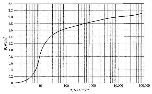
FIG. 10--DC magnetization curve for M-5 grain-oriented electrical steel
0.012 in thick.
4. AC EXCITATION
In ac power systems, the waveforms of voltage and flux closely approximate sinusoidal functions of time. This section describes the excitation characteristics and losses associated with steady-state ac operation of magnetic materials under such operating conditions. We use as our model a closed-core magnetic circuit, i.e., with no air gap, such as that shown in Fig. 1 or the transformer of Fig. 2.4. The magnetic path length is lc, and the cross-sectional area is Ac throughout the length of the core. We further assume a sinusoidal variation of the core flux ~o(t); thus
(Eqn. 48)
... where t~max -amplitude of core flux ~o in webers Bma x = amplitude of flux density Bc in teslas
From Eq. 27, the voltage induced in the N-turn winding is
(Eqn. 49)
where
(Eqn. 50)
In steady-state ac operation, we are usually more interested in the root-mean-square or rms values of voltages and currents than in instantaneous or maximum values. In general, the rms value of a periodic function of time, f(t), of period T is defined as ...
(Eqn. 51)
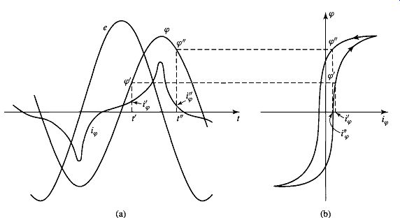
FIG. 11 Excitation phenomena. (a) Voltage, flux, and exciting current" (b)
corresponding hysteresis loop.
From Eq. 51, the rms value of a sine wave can be shown to be 1 / ~/2 times its peak value. Thus the rms value of the induced voltage is ...
(Eqn. 52)
To produce magnetic flux in the core requires current in the exciting winding known as the exciting current, […]. 6
The nonlinear magnetic properties of the core require that the waveform of the exciting current differs from the sinusoidal waveform of the flux. A curve of the exciting current as a function of time can be found graphically from the magnetic characteristics of the core material, as illustrated in Fig. 1 la.
Since Bc and Hc are related to ~o and i~ by known geometric constants, the ac hysteresis loop of Fig. 1 lb has been drawn in terms of ~o = BcAc and is i~0 = Hclc/N. Sine waves of induced voltage, e, and flux, ~o, in accordance with Eqs. 48 and 49, are shown in Fig. 11 a.
At any given time, the value of i~ corresponding to the given value of flux can be found directly from the hysteresis loop. For example, at time t t the flux is ~o t and […]
Notice that since " at time t" the corresponding values are ~o" and t~. the current is t~, the hysteresis loop is multi-valued, it is necessary to be careful to pick the rising-flux values (tp' in the figure) from the rising-flux portion of the hysteresis loop; similarly the falling-flux portion of the hysteresis loop must be selected for the falling-flux values (~o" in the figure).
[6. More generally, for a system with multiple windings, the exciting mmf is the net ampere-turns acting to produce flux in the magnetic circuit. ]
Notice that, because the hysteresis loop "flattens out" due to saturation effects, the waveform of the exciting current is sharply peaked. Its rms value I~0,rms is defined by Eq. 51, where T is the period of a cycle. It is related to the corresponding rms value nc,rms of n c by the relationship
(Eqn. 53)
The ac excitation characteristics of core materials are often described in terms of rms voltamperes rather than a magnetization curve relating B and H. The theory behind this representation can be explained by combining Eqs. 1.52 and 1.53. Thus, from Eqs. 1.52 and 1.53, the rms voltamperes required to excite the core of Fig. 1 to a specified flux density is equal to ErmsI~0,rms~/27r f (Eqn. 54)
In Eq. 54, the product Aclc can be seen to be equal to the volume of the core and hence the rms exciting voltamperes required to excite the core with sinusoidal can be seen to be proportional to the frequency of excitation, the core volume and the product of the peak flux density and the rms magnetic field intensity. For a magnetic material of mass density Pc, the mass of the core is AclcPc and the exciting rms voltamperes per unit mass, Pa, can be expressed as
(Eqn. 55)
Note that, normalized in this fashion, the rms exciting voltamperes can be seen to be a property of the material alone. In addition, note that they depend only on Bmax because Hrms is a unique function of Bmax as determined by the shape of the material hysteresis loop at any given frequency f. As a result, the ac excitation requirements for a magnetic material are often supplied by manufacturers in terms of rms voltamperes per unit weight as determined by laboratory tests on closed-core samples of the material. These results are illustrated in Fig. 12 for M-5 grain-oriented electrical steel.
The exciting current supplies the mmf required to produce the core flux and the power input associated with the energy in the magnetic field in the core. Part of this energy is dissipated as losses and results in heating of the core. The rest appears as reactive power associated with energy storage in the magnetic field. This reactive power is not dissipated in the core; it is cyclically supplied and absorbed by the excitation source.
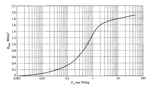
FIG. 12 Exciting rms voltamperes per kilogram at 60 Hz for M-5 grain-oriented
electrical steel 0.012 in thick. (Armco Inc.)
Two loss mechanisms are associated with time-varying fluxes in magnetic materials. The first is ohmic I2R heating, associated with induced currents in the core material. From Faraday's law (Eq. 26) we see that time-varying magnetic fields give rise to electric fields. In magnetic materials these electric fields result in induced currents, commonly referred to as eddy currents, which circulate in the core material and oppose changes in flux density in the material. To counteract the corresponding demagnetizing effect, the current in the exciting winding must increase. Thus the resultant "dynamic" B-H loop under ac operation is somewhat "fatter" than the hysteresis loop for slowly varying conditions, and this effect increases as the excitation frequency is increased. It is for this reason that the characteristics of electrical steels vary with frequency and hence manufacturers typically supply characteristics over the expected operating frequency range of a particular electrical steel. Note for example that the exciting rms volt-amperes of Fig. 12 are specified at a frequency of 60 Hz.
To reduce the effects of eddy currents, magnetic structures are usually built of thin sheets of laminations of the magnetic material. These laminations, which are aligned in the direction of the field lines, are insulated from each other by an oxide layer on their surfaces or by a thin coat of insulating enamel or varnish. This greatly reduces the magnitude of the eddy currents since the layers of insulation interrupt the current paths; the thinner the laminations, the lower the losses. In general, eddy-current loss tends to increase as the square of the excitation frequency and also as the square of the peak flux density.
The second loss mechanism is due to the hysteretic nature of magnetic material.
In a magnetic circuit like that of Fig. 1 or the transformer of Fig. 2.4, a time-varying excitation will cause the magnetic material to undergo a cyclic variation described by a hysteresis loop such as that shown in Fig. 13.
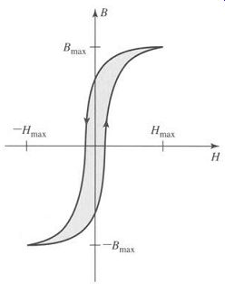
FIG. 13 Hysteresis loop; hysteresis loss is proportional to the loop
area (shaded).
Equation 45 can be used to calculate the energy input W to the magnetic core of Fig. 1 as the material undergoes a single cycle.

(Eqn. 56)
Recognizing that Aclc is the volume of the core and that the integral is the area of the ac hysteresis loop, we see that each time the magnetic material undergoes a cycle, there is a net energy input into the material. This energy is required to move around the magnetic dipoles in the material and is dissipated as heat in the material. Thus for a given flux level, the corresponding hysteresis losses are proportional to the area of the hysteresis loop and to the total volume of material. Since there is an energy loss per cycle, hysteresis power loss is proportional to the frequency of the applied excitation.
In general, these losses depend on the metallurgy of the material as well as the flux density and frequency. Information on core loss is typically presented in graphical form. It is plotted in terms of watts per unit weight as a function of flux density; often a family of curves for different frequencies are given. FIG. 14 shows the core loss Pc for M-5 grain-oriented electrical steel at 60 Hz.
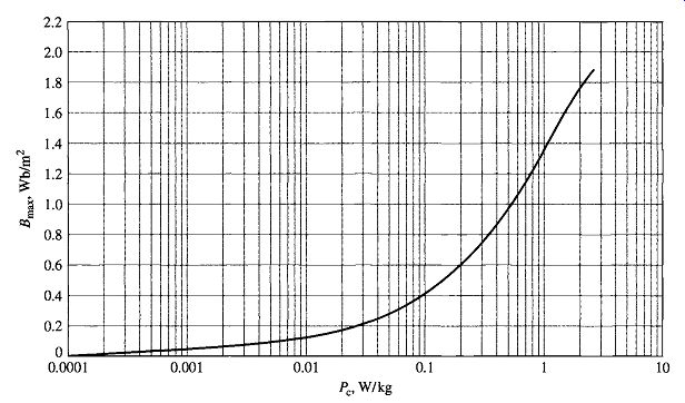
FIG. 14 Core loss at 60 Hz in watts per kilogram for M-5 grain-oriented
electrical steel 0.012 in thick. (Armco Inc.)
Nearly all transformers and certain sections of electric machines use sheet-steel material that has highly favorable directions of magnetization along which the core loss is low and the permeability is high. This material is termed grain-oriented steel.
The reason for this property lies in the atomic structure of a crystal of the silicon-iron alloy, which is a body-centered cube; each cube has an atom at each comer as well as one in the center of the cube. In the cube, the easiest axis of magnetization is the cube edge; the diagonal across the cube face is more difficult, and the diagonal through the cube is the most difficult. By suitable manufacturing techniques most of the crystalline cube edges are aligned in the rolling direction to make it the favorable direction of magnetization. The behavior in this direction is superior in core loss and permeability to nonoriented steels in which the crystals are randomly oriented to produce a material with characteristics which are uniform in all directions. As a result, oriented steels can be operated at higher flux densities than the nonoriented grades.
Non-oriented electrical steels are used in applications where the flux does not follow a path which can be oriented with the rolling direction or where low cost is of importance. In these steels the losses are somewhat higher and the permeability is very much lower than in grain-oriented steels.
5. PERMANENT MAGNETS
FIG. 16a shows the second quadrant of a hysteresis loop for Alnico 5, a typical permanent-magnet material, while Fig. 16b shows the second quadrant of a hysteresis loop for M-5 steel. 7 Notice that the curves are similar in nature. However, the hysteresis loop of Alnico 5 is characterized by a large value of residual flux density or remanent magnetization, Br, (approximately 1.22 T) as well as a large value of coercivity, Hc, (approximately -49 kA/m). The remanent magnetization, Br, corresponds to the flux density which would remain in a closed magnetic structure, such as that of Fig. 1, made of this material, if the applied mmf (and hence the magnetic field intensity H) were reduced to zero.
However, although the M-5 electrical steel also has a large value of remanent magnetization (approximately 1.4 T), it has a much smaller value of coercivity (approximately -6 A/m, smaller by a factor of over 7500). The coercivity Hc corresponds to the value of magnetic field intensity (which is proportional to the mmf) required to reduce the material flux density to zero.
The significance of remanent magnetization is that it can produce magnetic flux in a magnetic circuit in the absence of external excitation (such as winding currents). This is a familiar phenomenon to anyone who has affixed notes to a refrigerator with small magnets and is widely used in devices such as loudspeakers and permanent-magnet motors.
[To obtain the largest value of remanent magnetization, the hysteresis loops of Fig. 16 are those which would be obtained if the materials were excited by sufficient mmf to ensure that they were driven heavily into saturation. This is discussed further in Section 1.6. ]
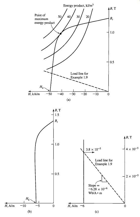
FIG. 16
(a) Second quadrant of hysteresis loop for Alnico 5; (b) second quadrant
of hysteresis loop for M-5 electrical steel; (c) hysteresis loop for M-5
electrical steel expanded for small B.
From Fig. 16, it would appear that both Alnico 5 and M-5 electrical steel would be useful in producing flux in unexcited magnetic circuits since they both have large values of remanent magnetization. That this is not the case can be best illustrated by an example.
Example 9 shows that there is an immense difference between permanent-magnet materials (often referred to as hard magnetic materials) such as Alnico 5 and soft magnetic materials such as M-5 electrical steel. This difference is characterized in large part by the immense difference in their coercivities He. The coercivity can be thought of as a measure of the magnitude of the mmf required to demagnetize the material. As seen from Example 9, it is also a measure of the capability of the material to produce flux in a magnetic circuit which includes an air gap. Thus we see that materials which make good permanent magnets are characterized by large values of coercivity He (considerably in excess of 1 kA/m). A useful measure of the capability of permanent-magnet material is known as its maximum energy product. This corresponds to the largest B-H product (B H)max, which corresponds to a point on the second quadrant of the hysteresis loop. As can be seen from Eq. 56, the product of B and H has the dimensions of energy density (joules per cubic meter). We now show that operation of a given permanent-magnet material at this point will result in the smallest volume of that material required to produce a given flux density in an air gap. As a result, choosing a material with the largest available maximum energy product can result in the smallest required magnet volume.
In Example 9, we found an expression for the flux density in the air gap of the magnetic circuit of (Eqn. 57)
We also found that the ratio of the mmf drops across the magnet and the air gap is equal to
(Eqn. 58)
Equation 58 can be solved for Hg, and the result can be multiplied by #0 to obtain Bg =/z0Hg. Multiplying by Eq. 57 yields
(Eqn. 59)
(Eqn. 60)
…where Volmag is the volume of the magnet, Volair gap is the air-gap volume, and the minus sign arises because, at the operating point of the magnetic circuit, H in the magnet (Hm) is negative.
Equation 60 is the desired result. It indicates that to achieve a desired flux density in the air gap, the required volume of the magnet can be minimized by operating the magnet at the point of the largest possible value of the B-H product Hm Bm, i.e., the point of maximum energy product. Furthermore, the larger the value of this product, the smaller the size of the magnet required to produce the desired flux density. Hence the maximum energy product is a useful performance measure for a magnetic material, and it is often found as a tabulated "figure of merit" on data sheets for permanent-magnet materials.
Note that Eq. 59 appears to indicate that one can achieve an arbitrarily large air-gap flux density simply by reducing the air-gap volume. This is not true in practice because as the flux density in the magnetic circuit increases, a point will be reached at which the magnetic core material will begin to saturate and the assumption of infinite permeability will no longer be valid, thus invalidating the derivation leading to Eq. 59.
Note also that a curve of constant B-H product is a hyperbola. A set of such hyperbolas for different values of the B-H product is plotted in Fig. 16a. From these curves, we see that the maximum energy product for Alnico 5 is 40 kJ/m 3 and that this occurs at the point
B = 1.0 T and H = -40 kA/m.
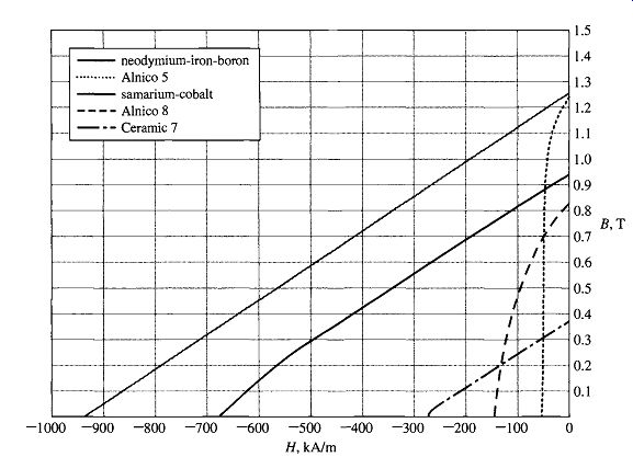
FIG. 19 Magnetization curves for common permanent-magnet materials.
6. APPLICATION OF PERMANENT MAGNET MATERIALS
Examples 9 and 10 consider the operation of permanent magnetic materials under the assumption that the operating point can be determined simply from a knowledge of the geometry of the magnetic circuit and the properties of the various magnetic materials involved. In fact, the situation is more complex. 8 This section will expand upon these issues.
FIG. 19 shows the magnetization characteristics for a few common permanent magnet materials. Alnico 5 is a widely used alloy of iron, nickel, aluminum, and cobalt, originally discovered in 1931. It has a relatively large residual flux density. Alnico 8 has a lower residual flux density and a higher coercivity than Alnico 5. Hence, it is less subject to demagnetization than Alnico 5. Disadvantages of the Alnico materials are their relatively low coercivity and their mechanical brittleness.
Ceramic permanent magnet materials (also known as ferrite magnets) are made from iron-oxide and barium or strontium-carbonate powders and have lower residual flux densities than Alnico materials but significantly higher coercivities. As a result, they are much less prone to demagnetization. One such material, Ceramic 7, is shown in Fig. 19, where its magnetization characteristic is almost a straight line. Ceramic magnets have good mechanical characteristics and are inexpensive to manufacture; as a result, they are the widely used in many permanent magnet applications.
Samarium-cobalt represents a significant advance in permanent magnet technology which began in the 1960s with the discovery of rare earth permanent magnet materials. From Fig. 19 it can be seen to have a high residual flux density such as is found with the Alnico materials, while at the same time having a much higher coercivity and maximum energy product. The newest of the rare earth magnetic materials is the neodymium-iron-boron material. It features even larger residual flux density, coercivity, and maximum energy product than does samarium-cobalt.
Consider the magnetic circuit of Fig. 20. This includes a section of hard magnetic material in a core of highly permeable soft magnetic material as well as an N-turn excitation winding. With reference to Fig. 21, we assume that the hard magnetic material is initially unmagnetized (corresponding to point a of the figure) and consider what happens as current is applied to the excitation winding. Because the core is assumed to be of infinite permeability, the horizontal axis of Fig. 21 can be considered to be both a measure of the applied current i = Hlm/N as well as a measure of H in the magnetic material.
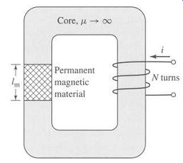
FIG. 20 Magnetic circuit including both a permanent magnet and an excitation
winding.
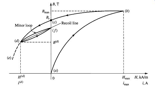
FIG. 21 Portion of a B-H characteristic showing a minor loop and a recoil
line.
As the current i is increased to its maximum value, the B-H trajectory rises from point a in Fig. 21 toward its maximum value at point b. To fully magnetize the material, we assume that the current has been increased to a value/max sufficiently large that the material has been driven well into saturation at point b. When the current is then decreased to zero, the B-H characteristic will begin to form a hysteresis loop, arriving at point c at zero current. At point c, notice that H in the material is zero but B is at its remanent value Br.
As the current then goes negative, the B-H characteristic continues to trace out a hysteresis loop. In Fig. 21, this is seen as the trajectory between points c and d.
If the current is then maintained at the value -i (d), the operating point of the magnet will be that of point d. Note that, as in Example 9, this same operating point would be reached if the material were to start at point c and, with the excitation held at zero, an air gap of length g = lm(Ag/Am)(-lzoH(d)/B (d)) were then inserted in the core.
Should the current then be made more negative, the trajectory would continue tracing out the hysteresis loop toward point e. However, if instead the current is returned to zero, the trajectory does not in general retrace the hysteresis loop toward point c. Rather it begins to trace out a minor hysteresis loop, reaching point f when the current reaches zero. If the current is then varied between zero and --i (d), the B-H characteristic will trace out the minor loop as shown.
As can be seen from Fig. 21, the B-H trajectory between points d and f can be represented by a straight line, known as the recoil line. The slope of this line is called the recoil permeability/ZR. We see that once this material has been demagnetized to point d, the effective remanent magnetization of the magnetic material is that of point f which is less than the remanent magnetization Br which would be expected based on the hysteresis loop. Note that should the demagnetization be increased past point d, for example, to point e of Fig. 21, a new minor loop will be created, with a new recoil line and recoil permeability.
The demagnetization effects of negative excitation which have just been discussed are equivalent to those of an air gap in the magnetic circuit. For example, clearly the magnetic circuit of Fig. 20 could be used as a system to magnetize hard magnetic materials. The process would simply require that a large excitation be applied to the winding and then reduced to zero, leaving the material at a remanent magnetization Br (point c in Fig. 21). Following this magnetization process, if the material were removed from the core, this would be equivalent to opening a large air gap in the magnetic circuit, demagnetizing the material in a fashion similar to that seen in Example 9. At this point, the magnet has been effectively weakened, since if it were again inserted in the magnetic core, it would follow a recoil line and return to a remanent magnetization somewhat less than Br. As a result, hard magnetic materials, such as the Alnico materials of Fig. 19, often do not operate stably in situations with varying mmf and geometry, and there is often the risk that improper operation can significantly demagnetize them. A significant advantage of materials such as Ceramic 7, samarium-cobalt and neodymium-iron-boron is that, because of their "straight-line" characteristic in the second quadrant (with slope close to/z0), their recoil lines closely match their magnetization characteristic. As a result, demagnetization effects are significantly reduced in these materials and often can be ignored.
At the expense of a reduction in value of the remanent magnetization, hard magnetic materials can be stabilized to operate over a specified region. This procedure, based on the recoil trajectory shown in Fig. 21, can best be illustrated by an example.
=========
Example 11
FIG. 22 shows a magnetic circuit containing hard magnetic material, a core and plunger of high (assumed infinite) permeability, and a single-turn winding which will be used to magnetize the hard magnetic material. The winding will be removed after the system is magnetized. The plunger moves in the x direction as indicated, with the result that the air-gap area can vary (2 cm 2 < Ag < 4 cm2). Assuming that the hard magnetic material is Alnico 5 and that the system is initially magnetized with Ag = 2 cm, (a) find the magnet length lm such that the system will operate on a recoil line which intersects the maximum B-H product point on the magnetization curve for Alnico 5, (b) devise a procedure for magnetizing the magnet, and (c) calculate the flux density Bg in the air gap as the plunger moves back and forth and the air gap varies between these two limits.
II Solution
a. FIG. 23a shows the magnetization curve for Alnico 5 and two load lines corresponding to the two extremes of the air gap, Ag -2 cm 2 and Ag = 4 cm 2. We see that the system will operate on the desired recoil line if the load line for Ag = 2 cm 2 intersects the B-H characteristic at the maximum energy product point (labeled point a in Fig. 23a), B~ ) = 1.0 T and H~m a) = -40 kMm.
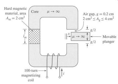
FIG. 22 Magnetic circuit for Example 11.
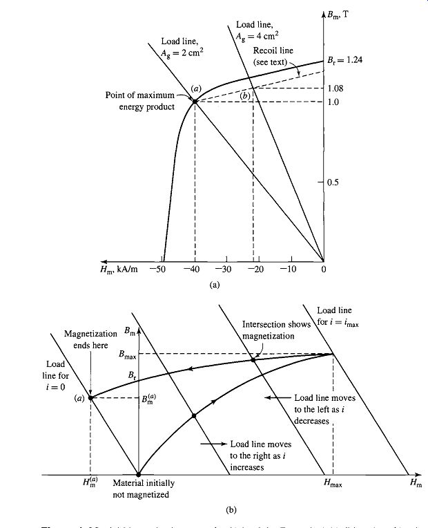
FIG. 23 (a) Magnetization curve for Alnico 5 for Example 11 (b) series
of load lines for Ag = 2 cm^2 and varying values of i showing the magnetization
procedure for Example 11.
In this case, we do not have a complete hysteresis loop for Alnico 5, and hence we will have to estimate Bmax and Hmax. Linearly extrapolating the B-H curve at H = 0 back to 4 times the coercivity, that is, Hmax = 4 x 50 = 200 kMm, yields nmax = 2.1 T. This value is undoubtedly extreme and will overestimate the required current somewhat.
However, using Bma x -2.1 T and Hma x --" 200 kA/m yields imax -45.2 A. Thus with the air-gap area set to 2 cm^2, increasing the current to 45.2 A and then reducing it to zero will achieve the desired magnetization.
c. Because we do not have specific information about the slope of the recoil line, we shall assume that its slope is the same as that of the B-H characteristic at the point H = 0, B = Br. From Fig. 23a, with the recoil line drawn with this slope, we see that as the air-gap area varies between 2 and 4 cm a, the magnet flux density Bm varies between 1.00 and 1.08 T. Since the air-gap flux density equals Am/Ag times this value, the airgap flux density will equal (2/2)1.00 = 1.0 T when Ag = 2.0 cm a and (2/4)1.08 = 0.54 T when ...
Ag = 4.0 cm^2. Note from Fig. 23a that, when operated with these air-gap variations, the magnet appears to have an effective residual flux density of 1.17 T instead of the initial value of 1.24 T. Note that as long as the air-gap variation is limited to the range considered here, the system will continue to operate on the line labeled "Recoil line" in Fig. 23a and the magnet can be said to be stabilized.
=================
As has been discussed, hard magnetic materials such as Alnico 5 can be subject to demagnetization, should their operating point be varied excessively. As shown in Example 11, these materials can be stabilized with some loss in effective remanent magnetization. However, this procedure does not guarantee absolute stability of operation. For example, if the material in Example 11 were subjected to an air-gap area smaller than 2 cm^2 or to excessive demagnetizing current, the effect of the stabilization would be erased and the material would be found to operate on a new recoil line with further reduced magnetization.
However, many materials, such as samarium-cobalt, Ceramic 7, and neodymium-boron (see Fig. 19), which have large values of coercivity, tend to have very low values of recoil permeability, and the recoil line is essentially tangent to the B-H characteristic for a large portion of the useful operating region. For example, this can be seen in Fig. 19, which shows the dc magnetization curve for neodymium-iron-boron, from which we see that this material has a remanent magnetization of 1.25 T and a coercivity of -940 kA/m. The portion of the curve between these points is a straight line with a slope equal to 1.06#0, which is the same as the slope of its recoil line. As long as these materials are operated on this low-incremental-permeability portion of their B-H characteristic, they do not require stabilization, provided they are not excessively demagnetized.
For these materials, it is often convenient to assume that their dc magnetization curve is linear over their useful operating range with a slope equal to the recoil permeability #R. Under this assumption, the dc magnetization curve for these materials can be written in the form
(Eqn. 61)
Here, H~ is the apparent coercivity associated with this linear representation. As can be seen from Fig. 19, the apparent coercivity is typically somewhat larger in magnitude (i.e. a larger negative value) than the material coercivity Hc because the dc magnetization characteristic tends to bend downward for low values of flux density.
7. SUMMARY
Electromechanical devices which employ magnetic fields often use ferromagnetic materials for guiding and concentrating these fields. Because the magnetic permeability of ferromagnetic materials can be large (up to tens of thousands times that of the surrounding space), most of the magnetic flux is confined to fairly well-defined paths determined by the geometry of the magnetic material. In addition, often the frequencies of interest are low enough to permit the magnetic fields to be considered quasi-static, and hence they can be determined simply from a knowledge of the net mmf acting on the magnetic structure.
As a result, the solution for the magnetic fields in these structures can be obtained in a straightforward fashion by using the techniques of magnetic-circuit analysis.
These techniques can be used to reduce a complex three-dimensional magnetic field solution to what is essentially a one-dimensional problem. As in all engineering solutions, a certain amount of experience and judgment is required, but the technique gives useful results in many situations of practical engineering interest.
Ferromagnetic materials are available with a wide variety of characteristics. In general, their behavior is nonlinear, and their B-H characteristics are often represented in the form of a family of hysteresis (B-H) loops. Losses, both hysteretic and eddy current, are functions of the flux level and frequency of operation as well as the material composition and the manufacturing process used. A basic understanding of the nature of these phenomena is extremely useful in the application of these materials in practical devices. Typically, important properties are available in the form of curves supplied by the material manufacturers.
Certain magnetic materials, commonly known as hard or permanent-magnet materials, are characterized by large values of remanent magnetization and coercivity.
These materials produce significant magnetic flux even in magnetic circuits with air gaps. With proper design they can be made to operate stably in situations which subject them to a wide range of destabilizing forces and mmf's. Permanent magnets find application in many small devices, including loudspeakers, ac and dc motors, microphones, and analog electric meters.
8. PROBLEMS
1. A magnetic circuit with a single air gap is shown in Fig. 24.
The core dimensions are:
Cross-sectional area Ac = 1.8 × 10^-3 m^2
Mean core length lc = 0.6 m
Gap length g = 2.3 x 10^-3 m
N = 83 turns
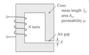
FIG. 24 Magnetic circuit for Problem 1.
Assume that the core is of infinite permeability (/x --+ c~) and neglect the effects of fringing fields at the air gap and leakage flux. (a) Calculate the reluctance of the core 7a,.c and that of the gap 7"¢.g. For a current of i = 1.5 A, calculate (b) the total flux ~, (c) the flux linkages )~ of the coil, and (d) the coil inductance L.
2. Repeat Problem 1 for a finite core permeability of/z = 2500/z0.
3. Consider the magnetic circuit of Fig. 24 with the dimensions of Problem 1. Assuming infinite core permeability, calculate (a) the number of turns required to achieve an inductance of 12 mH and (b) the inductor current which will result in a core flux density of 1.0 T.
4. Repeat Problem 3 for a core permeability of/x = 1300/z0.
5. The magnetic circuit of Problem 1 has a nonlinear core material whose permeability as a function of Bm is given by
…. where Bm is the material flux density.
a. Using MATLAB, plot a dc magnetization curve for this material (Bm vs. Hm) over the range 0 < Bm < 2.2 T.
b. Find the current required to achieve a flux density of 2.2 T in the core.
c. Again, using MATLAB, plot the coil flux linkages as a function of coil current as the current is varied from 0 to the value found in part (b).
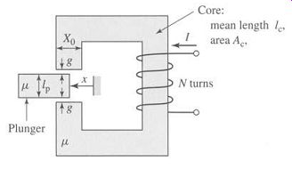
FIG. 25 Magnetic circuit for Problem 6.
6. The magnetic circuit of Fig. 25 consists of a core and a moveable plunger of width lp, each of permeability/z. The core has cross-sectional area Ac and mean length Ic. The overlap area of the two air gaps Ag is a function of the plunger position x and can be assumed to vary as
[…]
You may neglect any fringing fields at the air gap and use approximations consistent with magnetic-circuit analysis.
a. Assuming that # --+ c~, derive an expression for the magnetic flux density in the air gap Bg as a function of the winding current I and as the
plunger position is varied (0 < x < 0.8X0). What is the corresponding flux density in the core?
b. Repeat part (a) for a finite permeability/z.
7. The magnetic circuit of Fig. 25 and Problem 6 has the following dimensions"
Ac=8.2cm^2
lc=23cm
lp = 2.8 cm
g = 0.8 mm
X0 = 2.5 cm
N = 430 turns
a. Assuming a constant permeability of/z = 2800/z0, calculate the current required to achieve a flux density of 1.3 T in the air gap when the plunger is fully retracted (x = 0).
b. Repeat the calculation of part (a) for the case in which the core and plunger are composed of a nonlinear material whose permeability is given by (1199)
/z=/z0 1+ v/1+0"05B 8
... where Bm is the magnetic flux density in the material.
c. For the nonlinear material of part (b), use MATLAB to plot the air-gap flux density as a function of winding current for x -0 and x = 0.5X0.
8. An inductor of the form of Fig. 24 has dimensions: Cross-sectional area Ac = 3.6 cm^2
Mean core length lc = 15 cm N 75 turns
Assuming a core permeability of/z = 2100/~0 and neglecting the effects of leakage flux and fringing fields, calculate the air-gap length required to achieve an inductance of 6.0 mH.
9. The magnetic circuit of Fig. 26 consists of rings of magnetic material in a stack of height h. The rings have inner radius Ri and outer radius Ro. Assume that the iron is of infinite permeability (/z --+ c~) and neglect the effects of magnetic leakage and fringing. For:
Ri -3.4 cm Ro = 4.0 cm h-2cm g = 0.2 cm
... calculate:
a. the mean core length lc and the core cross-sectional area Ac.
b. the reluctance of the core ~c and that of the gap ~g.
For N = 65 turns, calculate:
c. the inductance L.
d. current i required to operate at an air-gap flux density of Bg = 1.35T.
e. the corresponding flux linkages ~. of the coil.
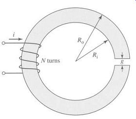
FIG. 26 Magnetic circuit for Problem 9.
10. Repeat Problem 9 for a core permeability of/z = 750/z0.
11. Using MATLAB, plot the inductance of the inductor of Problem 9 as a function of relative core permeability as the core permeability varies for
/z r = 100 to/Zr = 10000.
(Hint: Plot the inductance versus the log of the relative permeability.) What is the minimum relative core permeability required to insure that the inductance is within 5 percent of the value calculated assuming that the core permeability is infinite?
12. The inductor of Fig. 27 has a core of uniform circular cross-section of area Ac, mean length lc and relative permeability/Zr and an N-turn winding. Write an expression for the inductance L.
13. The inductor of Fig. 27 has the following dimensions: Ac = 1.0 cm 2 lc = 15 cm g = 0.8 mm N = 480 turns
Neglecting leakage and fringing and assuming #r -1000, calculate the inductance.
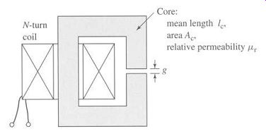
FIG. 27 Inductor for Problem 12.
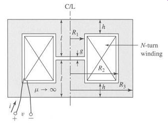
FIG. 28 Pot-core inductor for Problem 15.
14. The inductor of Problem 13 is to be operated from a 60-Hz voltage source. (a) Assuming negligible coil resistance, calculate the rms inductor voltage corresponding to a peak core flux density of 1.5 T. (b) Under this operating condition, calculate the rms current and the peak stored energy.
15. Consider the magnetic circuit of Fig. 28. This structure, known as a pot-core, is typically made in two halves. The N-turn coil is wound on a cylindrical bobbin and can be easily inserted over the central post of the core as the two halves are assembled. Because the air gap is internal to the core, provided the core is not driven excessively into saturation, relatively little magnetic flux will "leak" from the core, making this a particularly attractive configuration for a wide variety of applications, both for inductors such as that of Fig. 27 and transformers.
Assume the core permeability to be/z = 2500/z0 and N = 200 turns. The following dimensions are specified:
R1= 1.5cm
R2=4cm
l=2.5cm
h=0.75cm
g=0.5mm
a. Find the value of R3 such that the flux density in the outer wall of the core is equal to that within the central cylinder.
b. Although the flux density in the radial sections of the core (the sections of thickness h) actually decreases with radius, assume that the flux density remains uniform. (i) Write an expression for the coil inductance and (ii) evaluate it for the given dimensions.
c. The core is to be operated at a peak flux density of 0.8 T at a frequency of 60 Hz. Find (i) the corresponding rms value of the voltage induced in the winding, (ii) the rms coil current, and (iii) the peak stored energy.
d. Repeat part (c) for a frequency of 50 Hz.
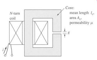
FIG. 29 Inductor for Problem 17.
16. A square voltage wave having a fundamental frequency of 60 Hz and equal positive and negative half cycles of amplitude E is applied to a 1000-turn winding surrounding a closed iron core of 1.25 x 10^-3m^2 cross section.
Neglect both the winding resistance and any effects of leakage flux.
a. Sketch the voltage, the winding flux linkage, and the core flux as a function of time.
b. Find the maximum permissible value of E if the maximum flux density is not to exceed 1.15 T.
17. An inductor is to be designed using a magnetic core of the form of that of Fig. 29. The core is of uniform cross-sectional area Ac = 5.0 cm^2 and of mean length Ic = 25 cm.
a. Calculate the air-gap length g and the number of turns N such that the inductance is 1.4 mH and so that the inductor can operate at peak currents of 6 A without saturating. Assume that saturation occurs when the peak flux density in the core exceeds 1.7 T and that, below saturation, the core has permeability/z = 3200/z0.
b. For an inductor current of 6 A, use Eq. 3.21 to calculate (i) the magnetic stored energy in the air gap and (ii) the magnetic stored energy in the core.
Show that the total magnetic stored energy is given by Eq. 47.
18. Consider the inductor of Problem 17. Write a simple design program in the form of a MATLAB script to calculate the number of turns and air-gap length as a function of the desired inductance. The script should be written to request a value of inductance (in mH) from the user, with the output being the air-gap length in mm and the number of turns.
The inductor is to be operated with a sinusoidal current at 60 Hz, and it must be designed such that the peak core flux density will be equal to 1.7 T when the inductor current is equal to 4.5 A rms. Write your script to reject any designs for which the gap length is out of the range of 0.05 mm to 5.0 mm or for which the number of turns drops below 5.
Using your program find (a) the minimum and (b) the maximum inductances (to the nearest mH) which will satisfy the given constraints. For each of these values, find the required air-gap length and the number of turns as well as the rms voltage corresponding to the peak core flux.
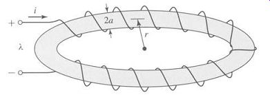
FIG. 30. Toroidal winding for Problem 19.
19. A proposed energy storage mechanism consists of an N-turn coil wound around a large nonmagnetic (/z -/~0) toroidal form as shown in Fig. 30. As can be seen from the figure, the toroidal form has a circular cross section of radius a and toroidal radius r, measured to the center of the cross section. The geometry of this device is such that the magnetic field can be considered to be zero everywhere outside the toroid. Under the assumption that a << r, the H field inside the toroid can be considered to be directed around the toroid and of uniform magnitude
Ni 2rc r
For a coil with
N = 1000 turns, r = 10 m, and a = 0.45 m:
a. Calculate the coil inductance L.
b. The coil is to be charged to a magnetic flux density of 1.75 T. Calculate the total stored magnetic energy in the toms when this flux density is achieved.
c. If the coil is to be charged at a uniform rate (i.e., di/dt = constant), calculate the terminal voltage required to achieve the required flux density in 30 sec. Assume the coil resistance to be negligible.
FIG. 31 Iron-core inductor for Problem 20.
20. FIG. 31 shows an inductor wound on a laminated iron core of rectangular cross section. Assume that the permeability of the iron is infinite. Neglect magnetic leakage and fringing in the two air gaps (total gap length = g). The N-turn winding is insulated copper wire whose resistivity is p ~.m. Assume that the fraction fw of the winding space is available for copper; the rest of the space is used for insulation.
a. Calculate the cross-sectional area and volume of the copper in the winding space.
b. Write an expression for the flux density B in the inductor in terms of the current density Jcu in the copper winding.
c. Write an expression for the copper current density Jcu in terms of the coil current I, the number of turns N, and the coil geometry.
d. Derive an expression for the electric power dissipation in the coil in terms of the current density Jcu.
e. Derive an expression for the magnetic stored energy in the inductor in terms of the applied current density Jcu.
f. From parts (d) and (e) derive an expression for the L/R time constant of the inductor. Note that this expression is independent of the number of turns in the coil and does not change as the inductance and coil resistance are changed by varying the number of turns.
21. The inductor of Fig. 31 has the following dimensions: a--h=w---1.5cm b=2cm g=0.2cm The winding factor (i.e., the fraction of the total winding area occupied by conductor) is fw = 0.55. The resistivity of copper is 1.73 × 10^-8 S^2.m.
When the coil is operated with a constant dc applied voltage of 35 V, the air-gap flux density is measured to be 1.4 T. Find the power dissipated in the coil, coil current, number of turns, coil resistance, inductance, time constant, and wire size to the nearest standard size. (Hint: Wire size can be found from the expression ( Awire ) AWG=36-4.3121n 1.267× 10^ -8 where AWG is the wire size, expressed in terms of the American Wire Gauge, and Awire is the conductor cross-sectional area measured in me.)
22. The magnetic circuit of Fig. 32 has two windings and two air gaps. The core can be assumed to be of infinite permeability. The core dimensions are indicated in the figure.
a. Assuming coil 1 to be carrying a current Il and the current in coil 2 to be zero, calculate (i) the magnetic flux density in each of the air gaps, (ii) the flux linkage of winding l, and (iii) the flux linkage of winding 2.
b. Repeat part (a), assuming zero current in winding 1 and a current I2 in winding 2.
c. Repeat part (a), assuming the current in winding 1 to be I1 and the current in winding 2 to be 12.
d. Find the self-inductances of windings 1 and 2 and the mutual inductance between the windings.
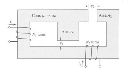
FIG. 32 Magnetic circuit for Problem 22.
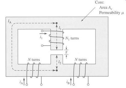
FIG. 33 Symmetric magnetic circuit for Problem 23.
23. The symmetric magnetic circuit of Fig. 33 has three windings. Windings A and B each have N turns and are wound on the two bottom legs of the core.
The core dimensions are indicated in the figure.
a. Find the self-inductances of each of the windings.
b. Find the mutual inductances between the three pairs of windings.
c. Find the voltage induced in winding 1 by time-varying currents iA(t) and iB (t) in windings A and B. Show that this voltage can be used to measure the imbalance between two sinusoidal currents of the same frequency.
24. The reciprocating generator of Fig. 34 has a movable plunger (position x) which is supported so that it can slide in and out of the magnetic yoke while maintaining a constant air gap of length g on each side adjacent to the yoke.
Both the yoke and the plunger can be considered to be of infinite permeability.
The motion of the plunger is constrained such that its position is limited to O<x<w.
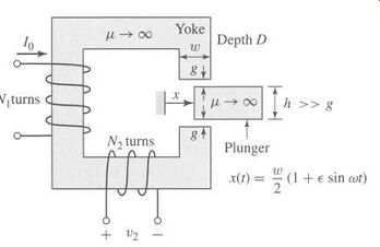
FIG. 34 Reciprocating generator for Problem 24.
There are two windings on this magnetic circuit. The first has N1 turns and carries a constant dc current I0. The second, which has N2 turns, is open-circuited and can be connected to a load.
a. Neglecting any fringing effects, find the mutual inductance between windings 1 and 2 as a function of the plunger position x.
b. The plunger is driven by an external source so that its motion is given by x(t) w (1 + E sin cot) ... where e < 1. Find an expression for the sinusoidal voltage which is generated as a result of this motion.
25. FIG. 35 shows a configuration that can be used to measure the magnetic characteristics of electrical steel. The material to be tested is cut or punched into circular laminations which are then stacked (with interspersed insulation to avoid eddy-current formation). Two windings are wound over this stack of laminations: the first, with Nt turns, is used to excite a magnetic field in the lamination stack; the second, with Ne turns, is used to sense the resultant magnetic flux.
The accuracy of the results requires that the magnetic flux density be uniform within the laminations. This can be accomplished if the lamination width t = Ro Ri is much smaller than the lamination radius and if the excitation winding is wound uniformly around the lamination stack. For the purposes of this analysis, assume there are n laminations, each of thickness A. Also assume that winding 1 is excited by a current i l = I0 sin wt.
a. Find the relationship between the magnetic field intensity H in the laminations and current i l in winding 1.
b. Find the relationship between the voltage ve and the time rate of change of the flux density B in the laminations.
c. Find the relationship between the voltage vo = G f v2 dt and the flux density.
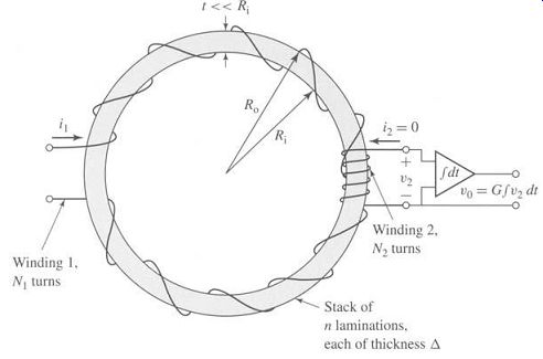
FIG. 35 Configuration for measurement of magnetic properties of electrical
steel.
In this problem, we have shown that the magnetic field intensity H and the magnetic flux density B in the laminations are proportional to the current il and the voltage v2 by known constants. Thus, B and H in the magnetic steel can be measured directly, and the B-H characteristics as discussed in Sections 1.3 and 1.4 can be determined.
26. From the dc magnetization curve of Fig. 10 it is possible to calculate the relative permeability/Zr = Be/(/~0Hc) for M-5 electrical steel as a function of the flux level Bc. Assuming the core of Fig. 2 to be made of M-5 electrical steel with the dimensions given in Example 1, calculate the maximum flux density such that the reluctance of the core never exceeds 5 percent of the reluctance of the total magnetic circuit.
27. In order to test the properties of a sample of electrical steel, a set of laminations of the form of Fig. 35 have been stamped out of a sheet of the electrical steel of thickness 3.0 mm. The radii of the laminations are Ri = 75 mm and Ro = 82 mm. They have been assembled in a stack of 10 laminations (separated by appropriate insulation to eliminate eddy currents) for the purposes of testing the magnetic properties at a frequency of 100 Hz.
a. The flux in the lamination stack will be excited from a variable-amplitude, 100-Hz voltage source whose peak amplitude is 30 V (peak-to-peak). Calculate the number of turns N1 for the excitation winding required to insure that the lamination stack can be excited up to a peak flux density of 2.0T.
b. With a secondary winding of N2 = 20 turns and an integrator gain G = 1000, the output of the integrator is observed to be 7.0 V peak-to-peak. Calculate (i) the corresponding peak flux in the lamination stack and (ii) the corresponding amplitude of the voltage applied to the excitation winding.
28. The coils of the magnetic circuit shown in Fig. 36 are connected in series so that the mmf's of paths A and B both tend to set up flux in the center leg C in the same direction. The coils are wound with equal turns, N1 = N2 = 100.
The dimensions are:
Cross-section area of A and B legs = 7 cm^2
Cross-section area of C legs = 14 cm^2
Length of A path = 17 cm
Length of B path = 17 cm
Length of C path = 5.5 cm
Air gap = 0.4 cm
The material is M-5 grade, 0.012-in steel, with a stacking factor of 0.94.
Neglect fringing and leakage.
a. How many amperes are required to produce a flux density of 1.2 T in the air gap?
b. Under the condition of part (a), how many joules of energy are stored in the magnetic field in the air gap? c. Calculate the inductance.
29. The following table includes data for the top half of a symmetric 60-Hz hysteresis loop for a specimen of magnetic steel:
Using MATLAB, (a) plot this data, (b) calculate the area of the hysteresis loop in joules, and (c) calculate the corresponding 60-Hz core loss in Watts/kg. The density of M-5 steel is 7.65 g/cm^3.
30. Assume the magnetic circuit of Problem 1 and Fig. 24 to be made up of M-5 electrical steel with the properties described in Figs. 10, 12, and 14.
Assume the core to be operating with a 60-Hz sinusoidal flux density of the rms flux density of 1.1 T. Neglect the winding resistance and leakage inductance. Find the winding voltage, rms winding current, and core loss for this operating condition. The density of M-5 steel is 7.65 g/cm^3.
31. Repeat Example 8 under the assumption that all the core dimensions are doubled.
32 Using the magnetization characteristics for samarium cobalt given in Fig. 19, find the point of maximum energy product and the corresponding flux density and magnetic field intensity. Using these values, repeat Example 10 with the Alnico 5 magnet replaced by a samarium-cobalt magnet. By what factor does this reduce the magnet volume required to achieve the desired air-gap flux density?
33. Using the magnetization characteristics for neodymium-iron-boron given in Fig. 19, find the point of maximum-energy product and the corresponding flux density and magnetic field intensity. Using these values, repeat Example 10 with the Alnico 5 magnet replaced by a neodymium-iron-boron magnet. By what factor does this reduce the magnet volume required to achieve the desired air-gap flux density?
34. FIG. 37 shows the magnetic circuit for a permanent-magnet loudspeaker.
The voice coil (not shown) is in the form of a circular cylindrical coil which fits in the air gap. A samarium-cobalt magnet is used to create the air-gap dc magnetic field which interacts with the voice coil currents to produce the motion of the voice coil. The designer has determined that the air gap must have radius R = 1.8 cm, length g = 0.1 cm, and height h = 0.9 cm.
Assuming that the yoke and pole piece are of infinite magnetic permeability (/z --+ oe), find the magnet height hm and the magnet radius Rm that will result in an air-gap magnetic flux density of 1.2 T and require the smallest magnet volume.
(Hint: Refer to Example 10 and to Fig. 19 to find the point of maximum energy product for samarium cobalt.)
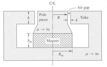
FIG. 37. Magnetic circuit for the loudspeaker of Problem 34 (voice
coil not shown).
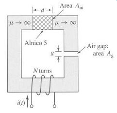
FIG. 38 Magnetic circuit for Problem 35.
35. It is desired to achieve a time-varying magnetic flux density in the air gap of the magnetic circuit of Fig. 38 of the form Bg = Bo + B1 sin cot where B0 = 0.5 T and Bl ---0.25 T. The dc field B0 is to be created by a neodymium-iron-boron magnet, whereas the time-varying field is to be created by a time-varying current.
For Ag = 6 cm^2, g = 0.4 cm, and N = 200 turns, find:
a. the magnet length d and the magnet area Am that will achieve the desired dc air-gap flux density and minimize the magnet volume.
b. the minimum and maximum values of the time-varying current required to achieve the desired time-varying air-gap flux density. Will this current vary sinusoidally in time?