AMAZON multi-meters discounts AMAZON oscilloscope discounts
1. Introduction
All countries now have a power system which transports electrical energy from generators to consumers. In some countries several separate systems may exist, but it is preferable to interconnect small systems and to operate the combination as one, so that economy of operation and security of supply to consumers is maximized. This integrated system (often known as the 'grid') has become dominant in most areas and it is usually considered as a major factor in the well-being and level of economic activity in a country.
All systems are based on alternating current, usually at a frequency of either 50 Hz or 60 Hz. 50 Hz is used in Europe, India, Africa and Australia, and 60 Hz is used in North and South America and parts of Japan.
Systems are traditionally designed and operated in the following three groupings:
the source of energy -- generation
bulk transfer -- transmission
supply to individual customers - distribution
2. Generation
Generators are required to convert fuels (such as coal, gas, oil and nuclear) and other energy sources (such as water, wind and solar radiation) into electrical power. Nearly all generators are rotating machines, which are controlled to provide a steady output at a given voltage; the main types of generator and the means of control are described in Section 5.
The total power output of all operating generators connected to the same integrated system must at every instant be equal to the sum of the consumer demand and the losses in the system. This implies careful and co-ordinated control such that the system frequency is maintained, because all generators in an ac power system must run in synchronism, that is their rotors, which produce a magnetic field, must lock into the rotating magnetic field produced by alternating currents in the stator winding.
Any excess of generated power over the absorbed power causes the frequency to rise, and a deficit causes the frequency to fall. As the demand of domestic, commercial and industrial consumers varies, so the generated power must also vary, and this is normally managed by transmission system control which instructs some generators to maintain a steady output and others (particularly hydro and gas turbine plant) to 'follow' the load; load 'following' is usually achieved by sensitive control of the input, dependent upon frequency. The aim of the system controller is to run the generating plant such that the overall cost of supplying the consumer at all times is a minimum, subject to the various constraints which are imposed by individual generator characteristics.
3. Transmission
Many large generators require easy access to their fuel supply and cooling water, so they cannot necessarily be sited close to areas of major consumption. Environmental constraints may also preclude siting close to areas of consumption. A bulk power transmission system is therefore needed between the generators and the consumers.
Large generating plant produces output ranging from 100 MW to 2000 MW and for economic reasons this normally operates with phase-to-phase voltages in the range 10 kV to 26 kV. In order to reduce transmission losses and so that transmission circuits are economic and environmentally acceptable, a higher voltage is necessary.
Phase-to-phase transmission voltages of up to 765 kV are used in sparsely populated large countries such as Brazil, the USA and Canada, but 380-400 kV is more prevalent in Europe. The standard voltages recommended by IEC are 765, 500, 380-400, 345, 275,230-220, 185-138 and 66-69 kV. Most transmission circuits are carried overhead on steel pylons. An example is shown in Fig. 1. They are suspended from insulators which provide sufficient insulation and air clearance to earth to prevent flashovers and danger to the public.
A typical suspension-type insulator is shown in Fig. 2. Each country has tended to have its own acceptable tower and conductor design. At higher voltages, Aluminum Conductor Steel Reinforced (ACSR) conductor is used, a core of steel strands providing the required strength. A typical cross-section for an ACSR conductor is shown in Fig. 3. For voltages over 200 kV two or more conductors per phase are used. This results in lower losses because of the large conductor cross-section, and lower radio interference and corona because of the lower voltage stress at the conductor surface.
Where an overhead line route is impossible because of congestion in an urban area or for environmental amenity reasons, buried cables may be employed, but the cost is 15-20 times higher than an equivalent overhead line. On sea crossings an underwater cable is the only solution, but these are often dc, for reasons explained in section 3.1.1.
A high-voltage transmission system interconnects many large generators with high areas of electricity demand; its reliability is paramount, since a failure could result in loss of supply to many people and to vital industry and services. The system is therefore arranged as a network so that the loss of one circuit can be tolerated. This is shown in Fig. 4. In many countries, three-phase lines are duplicated on one tower, in which case a tower failure might still result in a partial blackout. Mixed-voltage systems are often carried on a single tower, but this is not the practice in the UK. In order to achieve flexibility of operation, circuits are marshaled at substations.
The substations may include transformers to convert from one voltage level to another, and switchgear to switch circuits and interrupt faults. Substations are normally outdoors and they occupy an extensive secure area, although compact indoor substations using SF6 have become more prevalent recently because of their improved reliability in adverse weather.
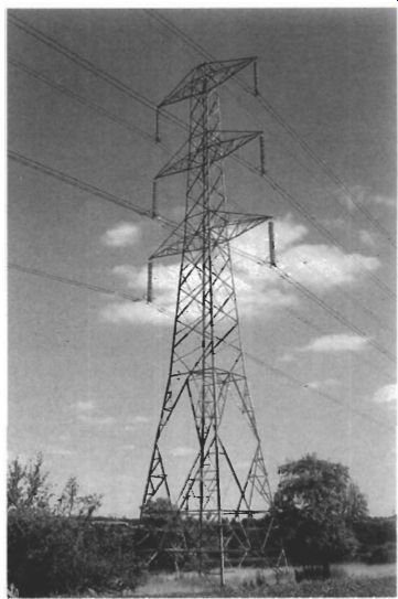
Fig. 1 Transmission line tower - a 400 kV double-circuit line
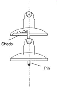
Fig. 2 Suspension-type insulator
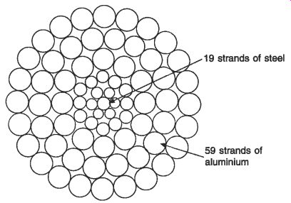
Fig. 3 Typical cross-section of ACSR overhead line conductor An interconnected
transmission network can comprise many substations which are all remotely controlled
and monitored to ensure rapid reconnection after a disturbance or to enable
maintenance.
3.1 Principles of design
The two main requirements of transmission systems are:
the interconnection of plant and neighboring systems to provide security, economic operation and the exchange of energy on a buy-sell basis
the transport of electrical energy from remote generation to load centers
These objectives are met by selection of the most economical overhead line design, commensurate with the various constraints imposed by environmental and national considerations. The design and approval process for new lines can take many years, following public enquiries and judicial proceedings before planning permission is granted and line construction begins. Typical objections to new overhead lines, particularly in industrialized countries, are:
the visual deterioration of open country areas
the possibility that electromagnetic field propagation may cause interference with television, radio and telecommunications, with an increasing awareness of carcinogenic risks
emission of noise by corona discharges, particularly at deteriorating conductor surfaces, joints and insulation surfaces
the danger to low-flying aircraft and helicopters
a preference for alternative energy supply such as gas and local environment-friendly generation including solar cells and wind power, or measures for reducing electricity demand such as better thermal insulation in houses and commercial premises, lower energy lighting, natural ventilation in place of air conditioning, and even changes of lifestyle
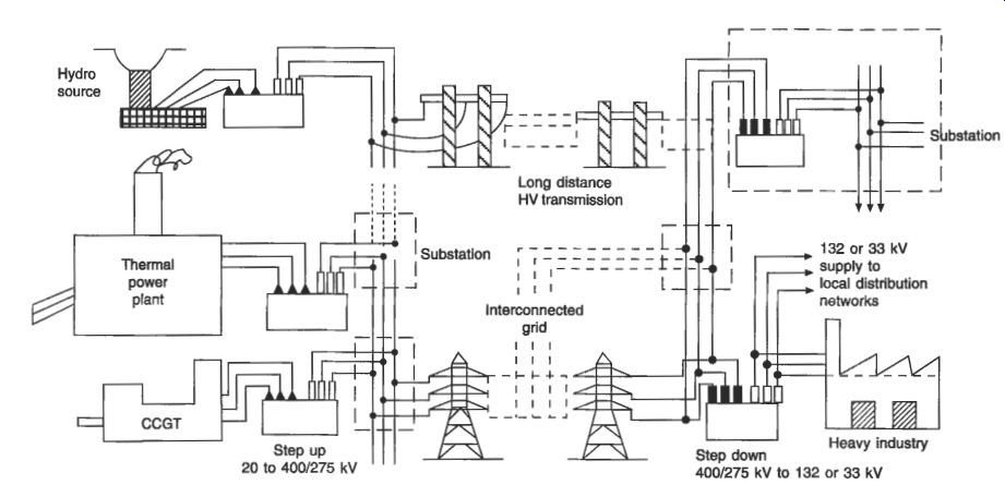
Fig. 4 Generation and transmission network ( UK voltages and practice)
Power system planners are required to show that extensive studies using a range of scenarios and sensitivities have been carried out, and that the most economical and least environmentally damaging design has been chosen. Impact statements are also required in many countries to address the concerns regarding the many issues raised by local groups, planning authorities and others.
Technically, the key issues which have to be decided are: whether to use an overhead line or underground cable the siting of substations and the size of substation required to contain the necessary equipment for control of voltage and power flow provision for future expansion, for an increase in demand, and in particular for the likelihood of tee-off connections to new load centers the availability of services and access to substation sites, including secure communications for control and monitoring
3.1.1 HVDC transmission
Direct current is being used increasingly for the high-voltage transport of electrical energy. The main reasons for using dc in preference to ac are:
dc provides an asynchronous connection between two ac systems which operate at different frequencies, or which are not in phase with each other. It allows real power to be dispatched economically, independently of differences in voltage or phase angle between the two ends of the link.
in the case of underground cables or undersea crossings, the charging current for ac cables would exceed the thermal capacity of the cable when the length is over about 50 km, leaving no capacity for the transfer of real power. A dc link overcomes this difficulty and a cable with a lower cross-section can be used for a given power transfer.
Where a line is several hundred kilometers long, savings on cost and improvements in appearance can be gained in the dc case by using just two conductors (positive and negative) instead of the three conductors needed in an ac system. Some security is provided should one dc conductor fail, since an emergency earth return can provide half power. The insulation required in a dc line is equivalent only to that required for the peak voltage in an ac system, and lower towers can therefore be used with considerable cost savings.
Against these reductions in cost with a dc line must be set the extra cost of solid- state conversion equipment at the interfaces between the ac and dc systems, and the corresponding harmonic correction and reactive compensation equipment which is required in the substations. It is normally accepted that the break-even distance is 50 km for cable routes and 300 km for overhead lines; above these distances dc is more economical than ac.
Because many ac systems already exist, and because the trading of energy across national and international boundaries is becoming more prevalent, dc transmission is being increasingly chosen as the appropriate link. An added advantage is that a dc infeed to a system allows fast control of transients and rapid balancing of power in the case of loss of a generator or other supply, and it does not contribute to the fault level of the receiving system; it is important here that when a short-circuit occurs on the ac system side, the current that flows can be safely interrupted by the ac-side circuit breaker.
The accepted disadvantages of a dc infeed, apart from the already-mentioned extra cost of conversion equipment, are the lack of an acceptable circuit breaker for flexible circuit operation, and the slightly higher power losses in the conversion equipment compared with an equivalent ac infeed.
With careful design of the transmission and conversion components, the reliability of dc and ac systems is comparable.
A typical HVDC scheme providing two-way power flow is shown schematically in Fig. 5. Each converter comprises rectifying components in the three-phase bridge connection, and each of the rectifying components consists of a number of thyristors connected is series and parallel. Increasingly, Gate Turn Off (GTO) thyristors are being used because of the greater control they allow. The current rating of each bridge component can be up to 200 A at 200 kV and bridges may be connected in series for higher voltages up to 400 kV or even 600 kV +/- to earth, each bridge being supplied from a three-phase converter transformer. By triggering the thyristors the current flow through the system can be controlled every few electrical degrees, hence rapid isolation can be achieved in the event of a fault on the system. Similarly, by delay triggering the current can be easily controlled, the direct voltage being best set by tap change on the converter supply transformers. The triggering of the thyristors may be by a light pulse which provides voltage isolation. Inversion, which enables power flow from the dc system to the ac system, depends on the ac back-emf being available with a minimum fault level in the receiving systems, so inversion into an isolated system is not possible unless devices with turn-off capability are available.
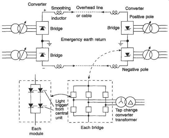
Fig. 5 Complete HVDC scheme: showing converters and dc link
A further feature of dc converter substations is the need for ac transmission filters to produce an acceptable ac sinusoidal waveform following the infeed or outfeed of almost square-wave blocks of current. Such filters for 6n f 1 harmonics (where n is the number of bridges and substations) can add 25 percent to the cost of a substation, although they can also be used to provide some of the VAr generation which is necessary to control the power factor of the inverter.
3.1.2 AC system compensation
As ac power systems become more extensive at transmission voltages, it is desirable to make provision for flexible operation with compensation equipment. Such equipment not only enables larger power flows to be accommodated in a given rating of ac circuit, but also provides a means of routing flows over the interconnected system for economic or trading purposes.
Compensation equipment consisting of fixed or variable inductance and capacitance can be connected in series with the circuit, in which case it must be rated to carry the circuit current, or it may be connected in shunt, and used to inject or absorb reactive power (VArs) depending upon requirements. In the same way that real power injected into the system must always just balance the load on the system and the system losses at that instant. so too must the reactive power achieve a balance over regions of the system.
Transmission circuits absorb VArs because their conductors are inductive, but they also generate VArs because they have a stray capacitance between phases and between phase and earth. The latter can be particularly important with high-voltage cables. The absorption is proportional to I^2X, where Z is the current and X is the reactance of the circuit, and the generation is proportional to V'B, where V is the voltage and B is the susceptance of the circuit. When I^2X is equal to V^2B at all parts of the circuit. it is found that the system voltage is close to the rated value. If V^2B is greater than Z'X, then the system voltage will be higher than the rated value, and vice versa. Designers therefore need to maintain a balance over the foreseeable range of current as loads vary from minimum to maximum during the day, and over the season and the year.
Compensation may be provided by the following three main methods:
--series capacitors connected in each phase to cancel the series inductance of the circuit. Up to 70 percent compensation is possible in this way.
--shunt inductance to absorb excessive VArs generated by the circuit stray capacitance or (exceptionally) to compensate for the leading power factor of a load
-- shunt capacitance to generate VArs for the compensation of load power factor or excessive VArs absorbed under heavy current flow conditions on short overhead line circuits
Combinations of these arrangements are possible, especially in transmission substations where no generators are connected; generators are able to generate or absorb VArs through excitation control.
Recently, Flexible AC Transmission Systems (FACTS) devices have become available. In these, the amount of VAr absorption by inductors is varied through the control of thyristors connected in series with the inductor limbs. A typical shunt controllable unit is shown in Fig. 6. This is known as a Shunt Variable Compensator (SVC). Other FACTS devices are variable series capacitors, variable phase shifters and Universal Power Controllers (UPC), in which energy is drawn from the system in shunt and injected back into the system in series at a controlled phase angle by means of GTO thyristors.
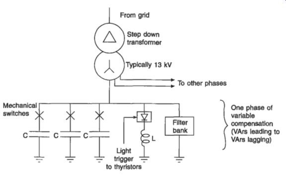
Fig. 6 Schematic of a Shunt Variable Compensator (SVC)
3.2 System operation
A transmission system may be vertically integrated, in which case the generating plant belongs to the same utility, or it may be unbundled, in which case it has only transmission capacity, with no generation plant. In either case the main tasks are to maintain a constant frequency and voltage for all consumers, and to operate the system economically and securely. Security in this context means maintaining voltage within limits, staying within a prescribed stability margin and operating all circuits within their thermal rating. This requires adequate monitoring of all the transmission components, with sufficient communication and control facilities to achieve these desired goals. Most transmission systems will, therefore, have a co-ordinating room and possibly a number of manned outstations for local or regional devolvement of responsibility.
For frequency control, some of the synchronized generators are equipped with sensitive governors which use a frequency signal rather than a speed signal. The output of these generators is dependent upon the balancing power required to achieve a steady frequency over the whole system. The control engineer, backed up by computer forecasts of load variations and knowledge of the available plant and their costs, can then instruct generators to start up or shut down (unit commitment) and set their output (loading or dispatching) so that over a prescribed hourly, daily or weekly period they generate energy to meet the consumer demand at the minimum overall cost. In the UK the use of a Generating Ordering And Loading (GOAL) program attempts to ensure that over a 24-hour period the total cost of generation commensurate with maintaining a secure system is the minimum that can possibly be provided. This includes the trading of energy with Scotland and France, in addition to any surplus power available from co-generation within industry and from renewable sources such as wind, hydro, waste incineration and landfill gas.
There is considerable scope for minimization of the losses in an interconnected system through the control of the compensation devices described in section 3.1.2.
This control is guided by the use of optimal load flow programs, security assessments
and calculations of transient stability margin. One of the main concerns is to arrange patterns of generation, including some plant which is out-of-merit, to maintain voltage despite outages of circuits and other components for maintenance, extension and repair. Safety of utility personnel and the operation of the system to avoid risk to the public are at all times paramount.
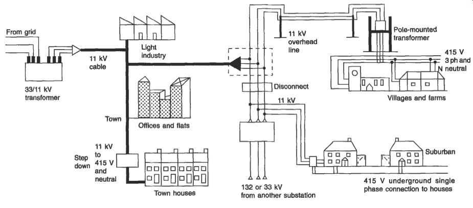
Fig. 7 Distribution network
4. Distribution
An example of a three-phase distribution system is illustrated in Fig. 7. In the UK, voltages of 132,110,66,33 and 11 kV are typically used to provide primary distribution, with a 380-415 V three-phase and neutral low-voltage supply to smaller consumers such as residential or smaller commercial premises, where 220-240 V single-phase to neutral is taken off the three-phase supply. Distribution voltages in continental Europe are typically 110,69 and 20 kV, but practice varies from country to country.
In the USA, voltages of 138, 115, 69, 34.5, 13.2 and 4.16 kV are employed.
The transformer stepping down from the primary distribution to the low-voltage supply may be pole mounted or in a substation, and is close to the consumers in order to limit the length of the low-voltage connection and the power losses in the low- voltage circuit. In a national power system, many thousands of transformers and their associated circuit breakers or fuses are required for distribution to low-voltage circuits, in contrast to high-voltage transmission and primary distribution systems, where the number of substations is in the hundreds.
It will be noted from Fig. 7 that the primary and low-voltage distribution systems are connected in a radial configuration. Circuit loops between adjacent substations are avoided because these can lead to circulating currents, which increase the power losses and create difficulty in protection schemes. However, tie circuits between adjacent lines and cables are available to reconfigure the network when a portion of the low-voltage circuit is out of service for maintenance or because of failure. These tie circuits are controlled by a normally open switch which can be closed manually within a few minutes, although an increasing trend is for automation of this operation by radio or tele-switching.
In urban and suburban areas, much of the primary and low-voltage distribution system is underground, with readily accessible substations sited in cellars or on small secure plots. Industrial sites may also have a number of substations incorporated into buildings or secure areas; these may be controlled by the works engineer or they may be operated and maintained by an electricity distribution company.
In rural areas and in more dispersed suburban areas, three-phase overhead lines operating at 10-15 kV or 27-33 kV are supported for many miles on poles which may be of wood, concrete or steel lattice. The 380-415 V three-phase supply is taken from these lines through a small pole-mounted fused input/output transformer. If the maximum load to be taken is below about 50 kW, the supplies for homes or farmsteads may be derived from a single-phase 10-15 kV supply. Typically, a rural primary distribution system supplies up to 50 step-down transformers spread over a wide region. The lines in such a system are vulnerable to damage by tree branches, snow and ice accumulation and lightning strikes and it therefore has lower reliability than underground systems in urban areas. Considerable ingenuity has been applied to protection of this type of system with the use of auto-reclosing supply circuit breakers and automatic reconnection switches, which are described in section 7.4.2(b). It is now common practice in developed countries to monitor the primary distribution system down to 10-15 kV and to display alarm, voltage and power-flow conditions in a control room, and in the event of an incident repair crews are dispatched quickly.
Repairs to the low-voltage system are still dependent, however, on consumers notifying a loss of supply.
The proper earthing of distribution systems is of prime importance in order that excessive voltages do not appear on connections to individual consumers. It is the practice in the UK and some other countries to connect to earth the neutral conductor of the 4-wire system and the star point of the low-voltage winding on the step-down transformer, not only at the transformer secondary output but also at every load point with a local meter and protective fuse. This is known as the Protective Multiple Earth (PME) system, which is described in relation to cable technology in section 9.3.1.3.
It is designed to ensure that all metallic covers and equipment fed from the supply are bonded so that dangerously high voltages do not hazard lives.
4.1 System design
It is essential that a distribution system is economical in operation and easy to repair, and its design should enable reconnection of a consumer through adjacent feeders to supply substations in the event of failure or outage of part of the system.
Copper or aluminum conductors with a cross-section of 150 mm2 to 250 mm2 are typically used at the lowest voltages, and these are arranged so that the maximum voltage drop under the heaviest load conditions is no more than 6 percent; alternatively the voltage at the connection to every consumer must not rise more than 6 percent under light load conditions. Local adjustment is achieved by off-load tap changing (usually f 2.5 percent or f 5 percent), and voltage in the primary circuits (usually 11 kV and 33 kV in the UK) is controlled by on-load tapchangers under automatic voltage control. The construction and operation of tapchangers is described in more detail in section 6.2.5. Reinforcement or extension on the LV network is usually arranged through the installation of a new primary feed point with a transformer, rather than by upgrading the LV network.
Primary underground networks now employ cross-linked polyethylene (XLPE) three-phase cables, as described in sections 9.2.4 and 9.3.1.3. The latest designs incorporate fiber-optic strands for communication purposes. Cables require careful routing and physical protection to minimize the risk of inadvertent damage from road and building works in the vicinity.
Overhead lines are usually of a simple, flat, three-phase configuration which avoids conductor clashing in high winds and ice precipitation. An example is shown in Fig. 7.20. Impregnated wood poles are normally used. These provide some degree of insulation to ground, and they can be quickly replaced in the event of collapse or decay. Insulators are usually of the cap-and-pin type, an example of which is illustrated in Fig. 8. Surge diverters and arcing horns provide a considerable measure of overvoltage protection, particularly where many kilometers of exposed line are fed from a primary substation. Arcing horns consist of a carefully positioned air gap between each conductor and earth. They are designed to flash over at a particular voltage when a potentially dangerous surge occurs on the system. Since there is no provision for extinguishing the resulting arc in this event, it is preferable, although more expensive, to provide a surge diverter at strategic positions in the overhead system. A surge diverter consists of a zinc oxide resistance between the live conductor and earth; this presents a very high resistance at normal voltages, but a low value at overvoltages, thereby conducting surge current safely to earth.
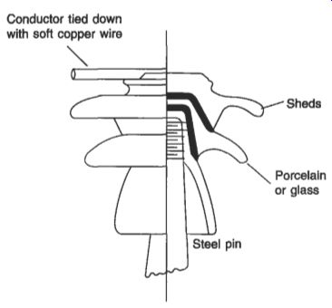
Fig. 8 Pin-type insulator
Primary substations consist usually of two or three step-down tapchanging transformers, with common busbars which may be duplicated for reliability and circuit separation. Remotely controlled interconnecting circuit breakers are installed to provide operating flexibility. Such substations are continuously monitored and metered, the data being brought back to a distribution control center for display and archiving. A modern tendency is to reduce the number of control centers and increase the geographical area covered by each through the use of computers and clever alarm handling and by analysis with powerful software which will in the future incorporate artificial intelligence.
4.2 System operation
The most important requirement in distribution control is good communication with district personnel and maintenance crews in order to ensure that maintenance and repair is efficiently, safely and swiftly carried out. Ready telephone access by the public and other consumers is also necessary so that dangerous situations or supply failures can be easily reported to engineers and technicians in the field.
The main task of the distribution controller is, therefore, to monitor equipment alarms and ensure that rapid and effective action is taken. Schedules of equipment outages and maintenance have to be planned and effected with the minimum of disruption to consumers.
5. Future trends
Power systems are continually evolving and with the increasing capability of computers and software, systems are becoming more centrally controlled for economy of operation and security.
There is a trend towards the separation of the ownership, management and control of generating plant from that of the transmission and distribution system. This is being accompanied by considerable economies in operating and technical personnel and is leading to more competitive trading.
Economists have constantly urged utilities to operate at marginal costs in order to achieve economic efficiency with the consequent downward pressure on prices, and this has led to the setting up of electrical energy markets in many countries. In such systems, entrepreneurial generators can enter with the expectation of making a profit by supplying electrical energy to any consumer over the transmission and distribution system. A charge has to be made for transport of energy over this system, but there is no reason to believe that this process will be more expensive than the previous vertically integrated system. Experience is beginning to show that such a market in electrical energy can work, as in the UK, and can produce cost savings not only in the supply of energy but also in its transportation.
References:
- Weedy, B.M. and Cory BJ. Electric Power System (4th edn), Wiley, 1987.
- EHV Transmission Line Reference Book, Edison Electric Institute, USA, 1968.
- Modem Power Station Practice, volume L, 3rd edn, Pergamon, 1991.