AMAZON multi-meters discounts AMAZON oscilloscope discounts
1. Scope
Thousands of cable types are used throughout the world. They are found in applications ranging from fiber-optic links for data and telecommunication purposes through to EHV underground power transmission at 275 kV or higher. The scope here is limited to cover those types of cable which fit within the general subject matter of this web guide.
This Section therefore covers cables rated between 300/500 V and 19/33 kV for use in the public supply network, in general industrial systems and in domestic and commercial wiring. Optical communication cables are included in a special section.
Overhead wires and cables, submarine cables and flexible appliance cords are not included.
Even within this relatively limited scope, it has been necessary to restrict the coverage of the major metallic cable and wire types to those used in the UK in order to give a cursory appreciation.
2 Principles of power cable design
2.1 Terminology
The voltage designation used by the cable industry does not always align with that adopted by users and other equipment manufacturers, so clarification may be helpful.
A cable is given a voltage rating which indicates the maximum circuit voltage for which it is designed, not necessarily the voltage at which it will be used. For example, a cable designated 0.6/1 kV is suitable for a circuit operating at 600 V phase-to-earth and 1000 V phase-to-phase. However, it would be normal to use such a cable on distribution and industrial circuits operating at 2301400 V in order to provide improved safety and increased service life. For light industrial circuits operating at 230/400 V it would be normal to use cables rated at 450/750 V, and for domestic circuits operating at 230/400 V, cable rated at 300/500 V would often be used. Guidance on the cables that are suitable for use in different locations is given in BS 7540. The terms LV (Low Voltage), MV (Medium Voltage) and HV (High Voltage) have different meanings in different sectors of the electrical industry. In the power cable industry the following bands are generally accepted and these are used in this Section:
LV - cable rated from 3001500 V to 1.913.3 kV
MV- cable rated from 3.816.6 kV to 19/33 kV
HV- cable rated at greater than 19/33 kV
Multicore cable is used in this Section to describe power cable having two to five cores. Control cable having seven to 48 cores is referred to as multicore control cable.
Cable insulation and sheaths are variously &scribed as thermoplastic, thermosetting, vulcanized, cross-linked, polymeric or elastomeric. All extruded plastic materials applied to cable are polymeric. Those which would re-melt if the temperature during use is sufficiently high are termed thermoplastic. Those which are modified chemically to prevent them from re-melting are termed thermosetting, cross-linked or vulcanized.
Although these materials will not re-melt, they will soften and deform at elevated temperatures if subjected to excessive pressure. The main materials within the two groups are as follows:
---thermoplastic
- polyethylene (PE)
- medium-density polyethylene (MDPE)
- polyvinyl chloride (PVC)
---thermosetting, cross-linked or vulcanized
- cross-linked polyethylene (XLPE)
- ethylene-propylene rubber WR)
Elastomeric materials are polymeric. They are rubbery in nature, giving a flexible and resilient extrusion. Elastomers are normally cross-linked, such as EPR.
2.2 General considerations
Certain design principles are common to power cables, whether they be used in the industrial sector or by the electricity supply industry.
For many cable types the conductors may be of copper or aluminum. The initial decision made by a purchaser will be based on price, weight, cable diameter, availability, the expertise of the jointers available, cable flexibility and the risk of theft. Once a decision has been made, however, that type of conductor will generally then be retained by that user, without being influenced by the regular changes in relative price which arise from the volatile metals market.
For most power cables, the form of conductor will be solid aluminum, stranded aluminum or stranded copper, although the choice may be limited in certain cable standards. Solid conductors provide for easier fitting of connectors and setting of the cores at joints and terminations. Cables with stranded conductors are easier to install because of their greater flexibility, and for some industrial applications a highly flexible conductor is necessary.
Where cable route lengths are relatively short a multicore cable is generally cheaper and more convenient to install than single-core cable. Single-core cables are sometimes used in circuits where high load currents require the use of large conductor sizes, between 500 mm^2 and 1200 mm^2. In these circumstances the parallel connection of two or more multicore cables would be necessary in order to achieve the required rating and this presents installation difficulties, especially at termination boxes. Single- core cable might also be preferred where duct sizes are small, where longer cable runs are needed between joint bays or where jointing and termination requirements dictate their use. It is sometimes preferable to use 3-core cable in the main part of the route length, and to use single-core cable to enter the restricted space of a termination box. In this case, a transition from one cable type to the other is achieved using trifurcating joints which are positioned several meters from the termination box.
Armored cables are available for applications where the rigors of installation are severe and where a high degree of external protection against impact during service is required. Steel Wire Armor (SWA) or Steel Tape Armor (STA) cables are available. Generally SWA is preferred because it enables the cable to be drawn into an installation using a pulling stocking which grips the outside of the oversheath and transfers all the pulling tension to the SWA. This cannot normally be done with STA cables because of the risk of dislocating the armor tapes during the pull. Glanding arrangements for SWA are simpler and they allow full usage of its excellent earth fault capability. In STA the earth fault capability is much reduced and the retention of this capability at glands is more difficult. The protection offered against a range of real-life impacts is similar for the two types.
2.3 Paper-insulated cables
Until the mid-1960s, paper-insulated cables were used worldwide for MV power circuits. There were at that time very few alternatives apart from the occasional trial installation or special application using PE or WC insulation.
The position is now quite different. There is a worldwide trend towards XLPE cable and, in the UK, the industrial sector has adopted XLPE-insulated or EPR- insulated cable for the majority of MV applications, paper-insulated cable now being restricted to minor uses such as extensions to older circuits or in special industrial locations. The use of paper-insulated cables for LV has been superseded completely by polymeric cables in all sectors throughout the world.
The success of polymeric-insulated cables has been due to the much easier, cleaner and more reliable jointing and termination methods that they allow. However, because of the large amount of paper-insulated cable still in service and its continued specification in some sectors for MV circuits, its coverage here is still appropriate.
Paper-insulated cables comprise copper or aluminum phase conductors which are insulated with lapped paper tapes, impregnated with insulating compound and sheathed with lead, lead alloy or corrugated aluminum. For mechanical protection, lead or lead alloy sheathed cables are finished off with an armoring of steel tapes or steel wire and a covering of either bitumenized hessian tapes or an extruded PVC oversheath.
Cables that are sheathed with corrugated aluminum need no further metallic protection, but they are finished off with a coating of bitumen and an extruded PVC oversheath; the purpose of the bitumen in this case is to provide additional corrosion protection should water penetrate the PVC sheath at joints, in damaged areas or by long-term permeation.
There are, therefore, several basic types of paper-insulated cable, and these are specified according to existing custom and practice as much as to meet specific needs and budgets. Particular features of paper-insulated cables used in the electricity supply industry and in industrial applications are given in sections 3.1.1 and 3.2.1 respectively.
The common element is the paper insulation itself. This is made up of many layers of paper tape, each applied with a slight gap between the turns. The purity and grade of the paper is selected for best electrical properties and the thickness of the tape is chosen to provide the required electrical strength.
In order to achieve acceptable dielectric strength all moisture and air is removed from the insulation and replaced by Mineral Insulating Non-Draining (MZND) compound. Its waxy nature prevents any significant migration of the compound during the lifetime of the cable, even at full operating temperature. This is in contrast to oil-filled HV cables, which must be pressurized throughout their service life to keep the insulation fully impregnated. Precautions are taken at joints and terminations to ensure that there is no local displacement of MIND compound which might cause premature failure at these locations. The paper insulation is impregnated with MIND compound during the manufacture of the cable, immediately before the lead or aluminum sheath is applied.
3-core construction is preferred in most MV paper-insulated cables. The three cores are used for the three phases of the supply and no neutral conductor is included in the design. The parallel combination of lead or aluminum sheath and amour can be used as an earth continuity conductor, provided that circuit calculations prove its adequacy for this purpose. Conductors of 95 mm^2 cross-section and greater are sector shaped so that when insulated they can be laid up in a compact cable construction.
Sector-shaped conductors are also used in lower cross-sections, down to 35, 50 and 70 mm2 for cables rated at 6, 10 and 15 kV respectively.
3-core 6.6 kV cables and most 3-core 11 kV cables are of the belted design. The cores are insulated and laid up such that the insulation between conductors is adequate for the full line-to-line voltage (6.6 kV or 11 kV). The laid-up cores then have an additional layer of insulating paper, known as the belt layer; applied and the assembly is then lead sheathed. The combination of core insulation and belt insulation is sufficient for phase-to-earth voltage between core and sheath (3.8 kV or 6.35 kV). 15, 22 and 33 kV 3-core cables and some 11 kV 3-core cables are of screened design. Here each core has a metallic screening tape and the core insulation is adequate for the full phase-to-earth voltage. The screened cores are laid up and the lead or aluminum sheath is then applied so that the screens make contact with each other and with the sheath.
The bitumenized hessian serving or PVC oversheath is primarily to protect the armor from corrosion in service and from dislocation during installation. The PVC oversheath is now preferred because of the facility to mark cable details, and its clean surface gives a better appearance when installed. It also provides a smooth firm surface for glanding and for sealing at joints.
2.4 Polymeric cables
PVC and PE cables were being used for LV circuits in the 1950s and they started to gain wider acceptance in the 1960s because they were cleaner, lighter, smaller and easier to install than paper-insulated types. During the 1970s the particular benefits of XLPE and HEPR insulations were being recognized for LV circuits and today it is these cross-linked insulations, mainly XLPE, which dominate the LV market with PVC usage in decline. LV XLPE cables are more standardized than MV polymeric types, but even so there is a choice of copper or aluminum conductor, single core or multicore, SWA or unarmored, and PVC or Low Smoke and Fume (LSF) sheathed.
A further option is available for LV in which the neutral and/or earth conductor is a layer of wires applied concentrically around the laid-up cores rather than as an insulated core within the cable. In this case the concentric each conductor can replace the armor layer as the protective metal layer for the cable.
For MV cables, polyethylene and PVC were shown to be unacceptable for use as general cable insulation in the years following the 1960s because their thermoplastic nature resulted in significant temperature limitations. XLPE and EPR were required in order to give the required properties. They allowed higher operating and short- circuit temperatures within the cable as well as the advantages of easier jointing and terminating than for paper-insulated cables. This meant that in some applications a smaller conductor size could be considered than had previously been possible in the paper-insulated case.
MV polymeric cables comprise copper or aluminum conductors insulated with XLPE or EPR and covered with a thermoplastic sheath of MDPE, PVC or LSF material. Within this general construction there are options of single-core or 3-core types, individual or collective screens of different sizes and armored or unarmored construction. Single-core polymeric cables are more widely used than single-core paper-insulated cables, particularly for electricity supply industry circuits. Unlike paper-insulated cables, polymeric 3-core cables normally have circular-section cores.
This is mainly because the increases in price and cable diameter are usually outweighed in the polymeric case by simplicity and flexibility of jointing and termination methods using circular cores.
Screening of the cores in MV polymeric cables is necessary for a number of reasons, which combine to result in a two-level screening arrangement. This comprises extruded semiconducting layers immediately under and outside the individual XLPE or EPR insulation layer, and a metallic layer in contact with the outer semiconducting layer. The semiconducting layers are polymeric materials containing a high proportion of carbon, giving them an electrical conductivity well below that of a metallic conductor, but well above that required for an insulating material. The term should not be confused with the semiconductor materials used in electronic components.
The two semiconducting layers must be in intimate contact in order to avoid partial discharge activity at the interfaces, where any minute air cavity in the insulation would cause a pulse of charge to transfer to and from the surface of the insulation in each half-cycle of applied voltage. These charge transfers result in erosion of the insulation surface and premature breakdown. In order to achieve intimate contact, the insulation and screens are extruded during manufacture as an integral triple layer and this is applied to the individual conductor in the same operation. The inner layer is known as the conductor screen and the outer layer is known as the core screen or dielectric screen.
When the cable is energized, the insulation acts as a capacitor and the core screen has to transfer the associated charging current to the insulation on every half-cycle of the voltage. It is therefore necessary to provide a metallic element in contact with the core screen so that this charging current can be delivered from the supply. Without this metallic element, the core screen at the supply end of the cable would have to carry a substantial longitudinal current to charge the capacitance which is distributed along the complete cable length, and the screen at the supply end would rapidly overheat as a result of excessive current density. However, the core screen is able to carry the current densities relating to the charging of a cable length of say 200 nun.
and this allows the use of a metallic element having an intermittent contact with the core screen, or applied as a collective element over three laid-up cores. A 0.08 mm thick copper tape is adequate for this purpose.
The normal form of armoring is a single layer of wire laid over an inner sheath of PVC or LSF material. The wire is of galvanized steel for 3-core cables and aluminum for single-core cables. Aluminum wire is necessary for single-core cables to avoid magnetizing or eddy-current losses within the amour layer. In unarmored cable the screen is required to carry the earth fault current resulting from the failure of any equipment being supplied by the cable or from failure of the cable itself. In this case, the copper tape referred to previously is replaced by a screen of copper wires of cross-section between say 6 mm^2 and 95 mm^2, depending on the earth fault capacity of the system.
2.5 Low Smoke and Fume (LSF) cables
Following a number of recent fire disasters, there has been a strong demand for cables which behave more safely in a fire. Cables have been developed to provide the following key areas of improvement: improved resistance to ignition reduced fire propagation reduced smoke emission reduced acid gas emission An optimized combination of these properties is achieved in LSF cables.
The original concept of LSF cables was identified through the requirements of underground railways in the 1970s. At that time, the main concern was to maintain sufficient visibility that orderly evacuation of passengers through a tunnel could be managed if the power to their train were interrupted by a fire involving the supply cables. This led to the development of a smoke test known as the '3-meter cube', this being based on the cross-section of a London Underground tunnel.
The demand for LSF performance has since spread to a wide range of products and applications, and the term LSF now represents a generic family of cables. Each LSF cable will meet the 3-meter cube test, but ignition resistance, acid gas emission and fire propagation performance is specified as appropriate to a particular product and application. For instance, a power cable used in large arrays in a power station has very severe fire propagation requirements, while a cable used in individual short links to equipment would have only modest propagation requirements.
3. Main classes of cable
3.1 Cables for the electricity supply industry
3.1.1 Paper-insulated cables
Until the late 1970s, the large quantities of paper-insulated cables used in the UK electricity supply industry for MV distribution circuits were manufactured according to BS 6480. These cables incorporated lead sheaths, steel wire armor and bitumenized textile beddings or servings. An example is illustrated in Fig. 1. The lead sheath provided an impermeable barrier to moisture and a return path for earth fault currents, and the layer of steel wire armor gave mechanical protection and an improved earth fault capacity.
Following successful trials and extensive installation in the early 1970s, a new standard (ESI 09-12) was issued in 1979 for Paper-Insulated Corrugated Aluminum
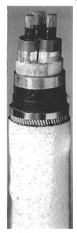
Fig. 1 Lead-sheathed, paper-insulated MV cable for the electricity supply
industry
Sheathed (PICAS) cable. This enabled the electricity supply industry to replace expensive lead sheath and steel-wire armor with a corrugated aluminum sheath which offered a high degree of mechanical protection and earth fault capability, while retaining the proven reliability of paper insulation. The standard was limited to three conductor cross-sections (95, 185 and 300 mm2), using stranded aluminum conductors with belted paper insulation. An example of PICAS cable is shown in Fig. 2. PICAS cable was easier and lighter to install than its predecessor and it found almost universal acceptance in the UK electricity supply sector.
3.1.2 MV polymeric cables
High-quality XLPE cable has been manufactured for over 25 years. IEC 502 (revised in 1998 as IEC 60502) covered this type of cable and was first issued in 1975. A comparable UK standard BS 6622 was issued in 1986 and revised in 1999.
The following features are now available in MV XLPE cables, and these are accepted by the majority of users in the electrical utility sector:
copper or aluminum conductors PVC or MDPE bedding
0 copper wire collective screens PVC or MDPE over-sheaths semiconducting conductor screen and core screen individual copper tape or copper wire screens steel wire or aluminum armor
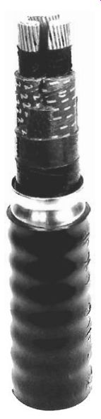
Fig. 2 Paper-Insulated Corrugated Aluminum Sheathed (PICAS) cable for
the electricity supply industry
Early experience in North America in the 1960s resulted in a large number of premature failures, mainly because of poor cable construction and insufficient care in avoiding contamination of the insulation. The failures were due to 'water treeing', which is illustrated in Fig. 3. In the presence of water, ionic contaminants and oxidation products, electric stress gives rise to the formation of tree-like channels in the XLPE insulation. These channels start either from defects in the bulk insulation (forming 'bow-tie' trees) or at the interfaces between the semiconducting screens and the insulation (causing 'vented' trees). Both forms of tree cause a reduction in electrical strength of the insulation and can eventually lead to breakdown. Water treeing has largely been overcome by better materials in the semiconducting screen and by improvements in the quality of the insulating materials and manufacturing techniques, and reliable service performance has now been established.
The UK electricity supply industry is to adopt XLPE-insulated or EPR-insulated cable for MV distribution circuits. Each distribution company is actively assessing the best construction for its particular needs. An example of the variation between companies is the difference in practice between solidly bonded systems and the use of earthing resistors to limit earth fault currents. In the former case the requirement might typically be to withstand an earth fault current of 13 kA for 3 seconds. In the latter case only 1 kA for 1 second might be specified, and the use of copper-wire collective screens in place of steel-wire armor is viable. The specific designs being used by the UK electricity supply industry are now incorporated into BS 7870-4.
Examples of XLPE cable designs being considered by UK distribution companies are shown in Figs 4, 9.5 and 9.6.
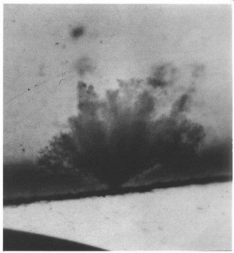
Fig. 3 Example of water treeing in a polymeric cable
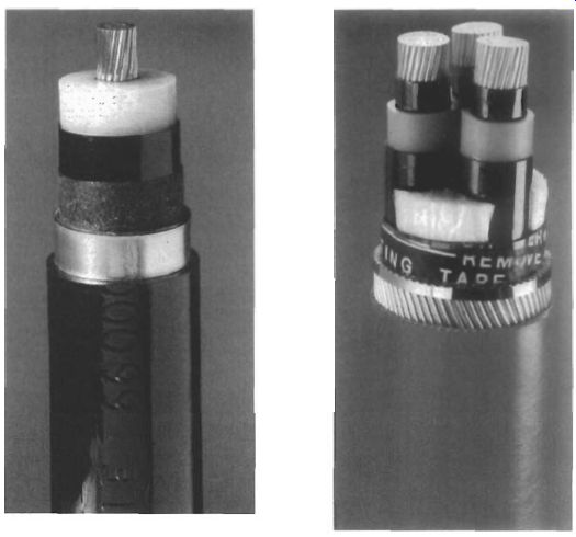
Fig. 4 Example of lead-sheathed XLPE-insulated cable for use in the
UK electricity supply industry
Fig. 5 Example of 3-core SWA XLPE-insulated cable for use in the UK electricity supply industry
3.1.3 LV polymeric cables
Protective Multiple Earthed (PME) systems which use Combined Neutral and Earth (CNE) cables have become the preferred choice in the UK public supply network, both for new installations and for extensions to existing circuits. This is primarily because of the elimination of one conductor by the use of a common concentric neutral and earth, together with the introduction of new designs which use aluminum for all phase conductors.
Before CNE types became established, 4-core paper-insulated sheathed and armored cable was commonly used. The four conductors were the three phases and neutral, and the lead sheath provided the path to the substation earth. The incentive for PME was the need to retain good earthing for the protection of consumers. With the paper cables, while the lead sheath itself could adequately carry prospective earth fault currents back to the supply transformer, the integrity of the circuit was often jeopardized by poor and vulnerable connections in joints and at terminations. By using the neutral conductor of the supply cable for this purpose, the need for a separate earth conductor was avoided.
The adoption of 0.6/1 kV cables with extruded insulation for underground public supply in the UK awaited the development of cross-linked insulation systems with a performance similar to paper-insulated systems in overload conditions. An example of the cables which have been developed is the 'Waveform' CNE type which is XLPE-insulated and has the neutral/earth conductor applied concentrically in a sinusoidal form. Insulated solid aluminum phase conductors are laid up to form a three-phase cable, and the CNE conductor consists of a concentric layer of either aluminum or copper wires.
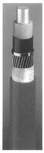
Fig. 6 Example of single-core copper-wire screen XLPE-insulated cable
for use in the UK electricity supply industry
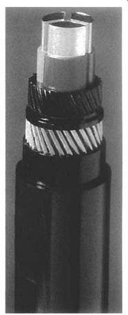
Fig. 7 Construction of a 'Waveform' XLPE- insulated CNE cable; 'Waveconal'
If the wires in the CNE conductor are of aluminum, they are sandwiched between layers of unvulcanized synthetic rubber compound to give maximum protection against corrosion. This construction is known as 'Waveconal' and is illustrated in Fig. 7. Where the CNE conductors are of copper, they are partially embedded in the rubber compound without a rubber layer over the wires. This is termed 'Wavecon' and is illustrated in Fig. 8. Some electricity companies have adopted Wavecon types because of concern over excessive corrosion in the aluminum CNE conductor.
Waveform cables are manufactured in accordance with BS 7870-3.
Both waveform types are compact, with cost benefits. The aluminum conductors and synthetic insulation result in a cable that is light and easy to handle. In addition, the waveform lay of the CNE conductors enables service joints to be readily made without cutting the neutral wires, as they can be formed into a bunch on each side of the phase conductors.
3.2 Industrial cables
'Industrial cables' are defined as those power circuit cables which are installed on the customer's side of the electricity supply point, but which do not fall into the category of 'wiring cables'. Generally these cables are rated 0.6/1 kV or above. They are robust in construction and are available in a wide range of sizes. They can be used for distribution of power around a large industrial site, or for final radial feeders to individual items of plant.
Feeder cables might be fixed, or in cases such as coal-face cutting machines and mobile cranes they may be flexible trailing or reeling cables.
Many industrial cables are supplied to customers' individual specifications and since these are not of general interest they are not described here. The following sections focus on those types of cable which are manufactured to national standards and which are supplied through cable distributors and wholesalers for general use.
Fig. 8 Construction of a 'Waveform' XLPE-insulated CNE cable; 'Wavecon'
3.2.1 Paper-insulated cables
For ratings between 0.6/1 kV and 19/33 kV, paper-insulated cables for fixed installations were supplied in the UK to BS 480, and then to BS 6480 following metrication in 1969. These cables comprise copper or aluminum phase conductors insulated with lapped paper tapes, impregnated with MIND compound and sheathed with lead or lead alloy. For mechanical protection they were finished with an armoring of steel tapes or steel wire and a covering of bitumenized hessian tapes or an extruded PVC oversheath.
3-core cables of this type with steel-wire armor have been preferred for most applications and these have become known as Paper-Insulated Lead-Covered Steel Wire Armored (PILCSWA) cables. Single-core cables to BS 6480 do not have armoring; this is partly because the special installation conditions leading to the selection of single core do not demand such protection, and partly because a non- magnetic armoring such as aluminum would be needed to avoid eddy current losses in the armor. These single-core cables are known as Paper-Insulated Lead Covered (PILC). It has already been observed that paper-insulated cables are now seldom specified for industrial use, but BS 6480 remains an active standard.
3.2.2 Polymeric cables for fixed installations
XLPE-insulated cables manufactured to BS 5467 are generally specified for 2301 400 V and 1.9/3.3 kV LV industrial distribution circuits. These cables have superseded the equivalent PVC-insulated cables to BS 6346 because of their higher current rating, higher short-circuit rating and better availability.
For MV applications in the range 3.816.6 kV to 19/33 kV, XLPE-insulated wire- armored cables to BS 6622 are usually specified.
Multicore LV and MV cables are normally steel-wire armored. This armoring not only provides protection against impact damage for these generally bulky and exposed cables, but it is also capable of carrying very large earth fault currents and provides a very effective earth connection.
Single-core cables are generally unarmored, although aluminum wire-armored versions are available. Single-core cables are usually installed where high currents are present (for instance in power stations) and where special precautions will be taken to avoid impact damage. For LV circuits of this type, the most economic approach is to use unarmored cable together with a separate earth conductor, rather than to connect in parallel the aluminum wire armor of several single-core cables.
For Mv applications each unarmored cable has a screen of copper wires which would, together, provide an effective earth connection.
Even in the harsh environment of coal mines, XLPE-insulated types are now offered as an alternative to the traditional PVC- and EPR-insulated cables used at LV and MV respectively. In this application the cables are always multicore types having a single or double layer of steel-wire armor. The armor has to have a specified minimum conductance because of the special safety requirements associated with earth faults and this demands the substitution of some steel wires by copper wires for certain cable sizes.
Where LSF fire performance is needed, LV wire-armored cables to BS 6724 are the established choice. These cables are identical in construction and properties to those made to BS 5467 except for the LSF grade of sheathing material and the associated fire performance. Cables meeting all the requirements of BS 6724 and, in addition, having a measure of fire resistance such that they continue to function in a fire are standardized in BS 7846, further details of which are given in section 3.3.
Similarly, BS 7835 for MV wire-armored cable, which is identical to BS 6622 apart from the LSF sheath and fire performance, was issued in 1996 and is currently under revision.
The only other type of standardized cable used for fixed industrial circuits is multicore control cable, often referred to as auxiliary cable. Such cable is used to control industrial plant, including equipment in power stations. It is generally wire armored and rated 0.6/1 kV. Cables of this type are available with between 5 and 48 cores. The constructions are similar to 0.6/1 kV power cables and they are manufactured and supplied to the same standards (BS 5467, BS 6346 and BS 6724, as appropriate). 9.3.2.3 Polymeric cables for flexible connections Flexible connections for both multicore power cables and multicore control cables are often required in industrial locations. The flexing duty varies substantially from application to application. At one extreme, a cable may need to be only flexible enough to allow the connected equipment to be moved occasionally for maintenance.
At the other extreme, the cable may be needed to supply a mobile crane from a cable reel, or a coal-face cutter from cable-handling gear.
Elastomeric-insulated and sheathed cable is used for all such applications. This may have flexible stranded conductors (known as 'class 5') or highly flexible stranded conductors (known as 'class 6'). Where metallic protection or screening is needed, this comprises a braid of fine steel or copper wires. For many flexible applications the cable is required to have a resistance to various chemicals and oils.
Although flexible cables will normally be operated on a 2301400 V supply, it is normal to use 450/750 V rated cables for maximum safety and integrity.
A number of cable types have been standardized in order to meet the range of performance requirements and the specification for these is incorporated into BS 6500. Guidance on the use of the cables is provided in this standard, and further information is available in BS 7540.
3.3 Wiring cables
The standard cable used in domestic and commercial wiring in the UK since the 1960s is a flat PVC twin-and-earth type, alternatively known as 6242Y cable. This comprises a flat formation of PVC-insulated live and neutral cores separated by a bare earth conductor, the whole assembly being PVC-sheathed to produce a flat cable rated at 300/500 V. Cable is also available with three insulated cores and a bare earth, for use on double-switched lighting circuits. These forms of cable are ideal for installation under cladding in standard-depth plaster. They are defined in BS 6004, which covers a large size range, only the smaller sizes of which are used in domestic and commercial circuits.
There are other cable types included in BS 6004 which have more relevance to non-domestic installations. These include cables in both flat and circular form, similar to the 6242'11 type but with an insulated earth conductor. Circular cables designated 6183Y are widely used in commercial or light industrial areas, especially where many circuits are mounted together on cable trays. Also included in BS 6004 are insulated conductors designated 6491Y which are pulled into conduit or trunking, in those circuits where mechanical protection or the facility to rewire are key factors.
An alternative type of cable with outstanding impact and crush strength is Mineral-Insulated Cable (MZCC) manufactured to BS 6207. This is often known by its trade name, Pyrotenax. In an MICC cable, the copper line and neutral conductors are positioned inside a copper sheath, the spaces between the copper components being filled with heavily compacted mineral powder of insulating grade. Pressure or impact applied to the cable merely compresses the powder in such a way that the insulation integrity is maintained. The copper sheath often acts as the circuit earth conductor.
An oversheath is not necessary, but is often provided for reasons of appearance or for external marking. MICC cable has a relatively small cross-section and is easy to install.
In shopping and office complexes or in blocks of flats there may be a need for a distribution sub-main to feed individual supply points or meters. If this sub-main is to be installed and operated by the owner of the premises, then a 0.6/1 kV split-concentric service cable to BS 4533 may be used. This comprises a phase conductor insulated in PVC or XLPE, around which are a layer of copper wires and an oversheath. Some of the copper wires are bare and these are used as the earth conductor. The remainder are polymer covered and they make up the neutral conductor. For larger installations, 3-core versions of this cable are available to manufacturers' specification.
LSF versions of the above cable types are available from several manufacturers.
Some of these have already been standardized according to BS 7211. In circuits supplying equipment for fire detection and alarm, emergency lighting and emergency supplies, regulations dictate that the cables will continue to operate during a fire.
This continued operation can be ensured by measures such as embedding the cable in masonry, but there is a growing demand for cables that are fire resistant in themselves.
Fire-resistance categories are set down in BS 6387.
The best fire resistance is offered by MICC cables, since the mineral insulation is unaffected by fire. MICC cable will only fail when the copper conductor or sheath melts and where such severe fires might occur the cable can be sheathed in LSF material to delay the onset of melting. MTCC cable is categorized CWZ in BS 6387.
Alternatives to MICC cables for fire resistance have been developed by individual manufacturers. Some rely on a filled silicone rubber insulation which degrades during a fire but continues to provide separation between the conductors so that circuit integrity is maintained. Other types supplement standard insulation with layers of mica tape so that even if the primary insulation bums completely the mica tape provides essential insulation to maintain supplies during the fire. These cable types are assigned minimum fire-resistance categories BWX and SWX respectively and manufacturers may claim fire resistance up to CWZ for their own products. Both cable types are standardized in BS 7629.
Some circuits requiring an equivalent level of fire resistance need to be designed with larger cables than are found in BS 7629. Such circuits might be for the main emergency supply, fire-fighting Lifts, sprinkler systems and water pumps, smoke extraction fans, fire shutters or smoke dampers. These larger cables are standardized in BS 7846, which includes the size range and LSF performance of BS 6724. These cables can be supplied to the CWZ performance level in BS 6387. However, there is an additional fire test category in BS 7846, called F3. which is considered to be more appropriate for applications where the cable might be subject to fire, impact and water spray in combination during the fire.
4. Parameters and test methods
There are a large number of cable and material properties which are controlled by the manufacturer in order to ensure fitness for purpose and reliable long-term service performance. However, it is the operating parameters of the finished installed cable which are of most importance to the user in cable selection. The major parameters of interest are as follows:
current rating capacitance inductance voltage drop earth loop impedance symmetrical fault capacity earth fault capacity
These are dealt with in turn in the following sections.
4.1 Current rating
The current rating of each individual type of cable could be measured by subjecting a sample to a controlled environment and by increasing the load current passing through the cable until the steady-state temperature of the limiting cable component reached its maximum permissible continuous level. This would be a very costly way of establishing current ratings for all types of cable in all sizes, in all environments and in all ambient temperatures. Current ratings are therefore obtained using an internationally accepted calculation method, published in IEC 60287. The formulae and reference material properties presented in JEC 60287 have been validated by correlation with data produced from laboratory experiments.
Current ratings are quoted in manufacturers' literature and are listed in IEE Wiring Regulations (BS 7671) for some industrial, commercial and domestic cables. The ratings are quoted for each cable type and size in air, in masonry, direct-in-ground and in underground ducts. Derating factors are given so that these quoted ratings can be adjusted for different environmental conditions such as ambient temperature, soil resistivity or depth of burial.
Information is given in BS 7671 and in the IEE Guidance Notes on the selection of the appropriate fuse or mcb to protect the cable from overload and fault conditions, and general background is given in sections 8.2 and 8.3.
4.2 Capacitance The capacitance data in manufacturers' literature is calculated from the cable dimensions 'and the permittivity of the insulation.
For example, the star capacitance of a 3-core belted armored cable to BS 6346 is the effective capacitance between a phase conductor and the neutral star point. It is calculated using the following formula:
[Wflunl EO 18 h[(d + tl + t2 )/d] C= where 6 = relative permittivity of the cable insulation (8.0 for PVC) d = diameter of the conductor [rnm] tl = thickness of insulation between the conductors [mm] t2 = thickness of insulation between conductor and armor [mm] Equation 9.1 assumes that the conductors are circular in section. For those cables having shaped conductors, the value of capacitance is obtained by multiplying the figure obtained using eqn 1 by an empirical factor of 1.08.
The calculated capacitance tends to be conservative, that is the actual capacitance will always be lower than the calculated value. However, if an unusual situation arises in which the cable capacitance is critical, then the manufacturer is able to make a measurement using a capacitance bridge.
If the measured capacitance between cores and between core and armor is quoted, then the star capacitance can be calculated using eqn 9.2:
...where C, = measured capacitance between one conductor and the other two connected together to the armor C,p = measured capacitance between three conductors connected together and the amour
4.3 Inductance
The calculation of cable inductance L for the same example of a 3-core armored cable to BS 6346 is given by eqn 9.3 as follows:
(eqn. 3)
L = 1.02 x I0.2 x ln[2Y/dJ + k} [mwkm]
where d = diameter of the conductor [mm]
Y = axial spacing between conductors [mm]
k = a factor which depends on the conductor make-up (k =0.064 for 7-wire stranded
0.055 for 19-wire stranded
0.053 for 37-wire stranded
0.050 for solid)
The same value of cable inductance L is used for cables with circular- or sector- shaped conductors.
4.4 Voltage drop
BS 7671 specifies that within customer premises the voltage drop in cables is to be a maximum value of 4 percent. It is therefore necessary to calculate the voltage drop along a cable.
The cable manufacturer calculates voltage drop assuming that the cable will be loaded with the maximum allowable current which results in the maximum allowable operating temperature of the conductor. The cable impedance used for calculating the voltage drop is given by eqn 9.4:
z = {R~ + (27cj~ - 1/27tf~~}~~ [am] (eqn. 4)
...where R = ac resistance of the conductor at maximum conductor temperature [Wm] L = inductance [Wm] C = capacitance [F/m] f= supply frequency [Hz] The voltage drop is then given by eqns 9.5 and 9.6: For single-phase circuits: and for three-phase circuits:
voltage drop = 22 [V/A/m] voltage drop = d 32 [V/A/m]
4.5 Symmetrical and earth fault capacity
It is necessary that cables used for power circuits are capable of carrying any fault currents that may flow, without damage to the cable; the requirements are specified in BS 7671. This assessment demands a knowledge of the maximum prospective fault currents on the circuit, the clearance characteristics of the protective device (as explained in Section 8) and the fault capacity of the relevant elements in the cable.
For most installations it is necessary to establish the let-through energy of the protective device and to compare this with the adiabatic heating capacity of the conductor (in the case of symmetrical and earth faults) or of the steel amour (in the case of earth faults).
The maximum let-through energy (I^2t) of the protective device is explained in Section 8. It can be obtained from the protective device manufacturer's data. In practice the value will be less than that shown by the manufacturer's information because of the reduction in current during the fault which results from the significant rise in temperature and resistance of the cable conductors.
The fault capacity of the cable conductor and amour can be obtained from information given in BS 7671 and the appropriate BS cable standard, as follows:
(eqn. 7)
k2S2 = adiabatic fault capacity of the cable element
where S = the nominal cross-section of the conductor or the nominal cross-section of, say, the armor [mm'] k = a factor reflecting the resistivity, temperature coefficient, allowable temperature rise and specific heat of the metallic cable element
(k = 115 for a PVC-insulated copper conductor within the cable = 176 for an XLPE-insulated copper earth conductor external = 46 for the steel armor of an XLPE-insulated cable) to the cable
In practice it will be found that provided the cable rating is at least equal to the nominal rating of the protective device and the maximum fault duration is less than 5 seconds, the conductors and armor of cables to BS will easily accommodate the let-through energy of the protective device.
It is also important that the impedance of the supply cable is not so high that the protective device takes too long to operate during a zero-sequence earth fault on connected equipment. This is important because of the need to protect any person in contact with the equipment, by limiting the time that the earthed casing of the equipment, say, can become energized during an earth fault.
This requirement, which is stated in BS 7671, places restrictions on the length of cable that can be used on the load side of a protective device, and it therefore demands a knowledge of the earth fault loop impedance of the cable. Some cable manufacturers have calculated the earth fault impedance for certain cable types and the data are presented in specialized literature. These calculations take account of the average temperature of each conductor and the reactance of the cable during the fault. The values are supported by independent experimental results. BS 7671 allows the use of such manufacturer's data or direct measurement of earth fault impedance on a completed installation.
5. Optical communication cables
The concept of using light to convey information is not new. There is historical evidence that Aztecs used flashing mirrors to communicate, and in 1880 Alexander Graham Bell first demonstrated his photophone. in which a mirror mounted on the end of a megaphone was vibrated by the voice to modulate a beam of sunlight, thereby transmitting speech over distances up to 200 m.
Solid-state photodiode technology has its roots in the discovery of the light- sensitive properties of selenium in 1873, used as the detector in Bell's photophone.
The Light Emitting Diode (LED) stems from the discovery in 1907 of the electroluminescent properties of silicon, and when the laser was developed in 1959, Information input (electrical)
Transmitter Receiver Information Connector
Connector output J Light (optical)
2. Optical fiber
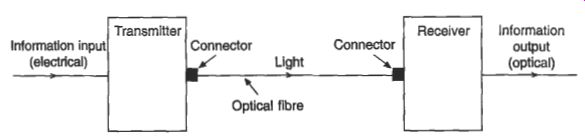
Fig. 9 Basic fiber optic system
5.1 Optical fibers
An optical fiber is a dielectric waveguide for the transmission of light, in the form of a thin filament of very transparent silica glass. As shown in Fig. 10, a typical fiber comprises a core, the cladding, a primary coating and sometimes a secondary coating or buffer. Within this basic construction, fibers are further categorized as multimode or single-mode fibers with a step or graded index.
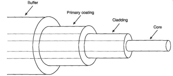
Fig. 10 Basic optical fiber
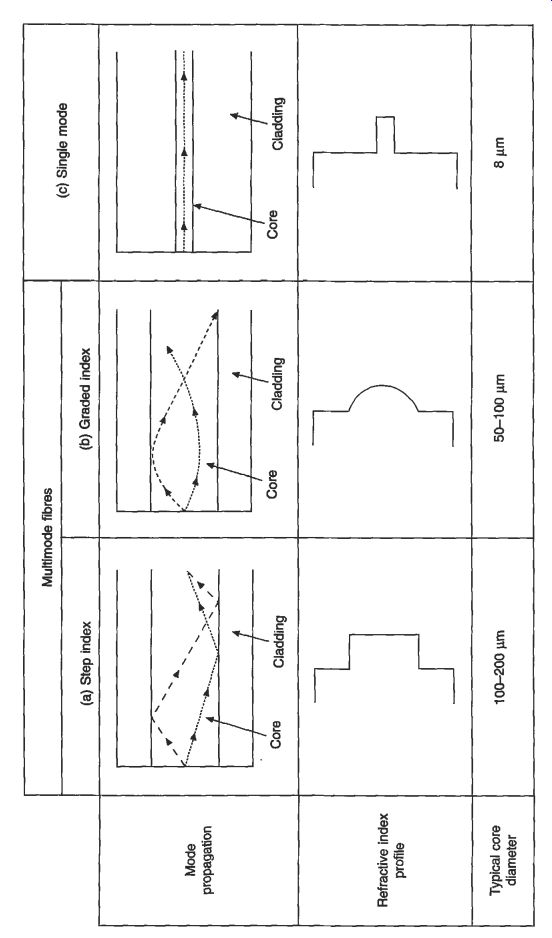
Fig. 11
The core is the part of the fiber that transmits light, and it is surrounded by a glass cladding of lower refractive index. In early fibers, the homogeneous core had a constant refractive index across its diameter, and with the refractive index of the cladding also constant (at a lower value) the profile across the whole fiber diameter, as shown in Fig. 11(a), became known as a step index. In this type of fiber the light rays can be envisaged as travelling along a zig-zag path of straight lines, kept within the core by total reflection at the inner surface of the cladding. Depending on the angle of the rays to the fiber axis, the path length will differ so that a narrow pulse of light entering the fiber will become broader as it travels. This sets a limit to the rate at which pulses can be transmitted without overlapping and hence a limit to the operating bandwidth.
To minimize this effect, which is known as mode dispersion, fibers have been developed in which the homogeneous core is replaced by one in which the refractive index varies progressively from a maximum at the center to a lower value at the interface with the cladding. Figure 11(b) shows such a graded index fiber, in which the rays no longer follow straight lines. When they approach the outer parts of the core, travelling temporarily faster, they are bent back towards the center where they travel more slowly. Thus the more oblique rays travel faster and keep pace with the slower rays travelling nearer the fiber center. This significantly reduces the pulse broadening effect of step index fibers.
The mode dispersion of step index fibers has also been minimized by the more recent development of single-mode fibers. As shown in Fig. 11(c), although it is a step index fiber, the core is so small (of the order of 8 pm in diameter) that only one mode can propagate.
Fiber manufacture involves drawing down a preform into a long thin filament.
The preform comprises both core and cladding, and for graded index fibers the core contains many layers with dopants being used to achieve the varying refractive index. Although the virgin fiber has a tensile strength comparable to that of steel, its strength is determined by its surface quality. Micro-cracks develop on the surface of a virgin fiber in the atmosphere, and the lightest touch or scratch makes the fiber impractically fragile. Thus it must be protected, in line with the glass drawing before it touches any solid object such as pulleys or drums, by a protective coating of resin, acetate or plastic material, called the primary coating.
Typically the primary coating has a thickness of about 60 pm, and in some cases a further layer of material called the buffer is added to increase the mechanical protection.
5.2 Optical cable design
The basic aim of a transmission cable is to protect the transmission medium from its environment and the rigors of installation. Conventional cables with metallic conductors are designed to function effectively in a wide range of environments, as shown in sections 2 and 3. However, optical fibers differ significantly from copper wires to an extent that has a considerable bearing on cable designs and manufacturing techniques. The transmission characteristics and lifetime of fibers are adversely affected by quite low levels of elongation, and lateral compressions can produce small kinks or sharp bends which create an increase in attenuation loss known as microbending loss. This means that cables must protect the fiber from strain during installation and service, and they must cater for longitudinal compression that occurs, for example, with a change in cable temperature.
Fiber life in service is influenced by the presence of moisture as well as stress.
The minute cracks which cover the surface of all fibers can grow if the fiber is stressed in the presence of water, so that the fiber could break after a number of years in service. Cables must be able to provide a long service life in such environments as tightly packed ducts which are filled with water.
The initial application of optical cables was the trunk routes of large telecommunications networks, where cables were directly buried or laid in ducts in very long lengths, and successful cable designs evolved to take into account the constraints referred to above. The advantages of fiber optics soon led to interest in other applications such as computer and data systems, military systems and industrial control. This meant that cable designs had to cater for tortuous routes of installation in buildings, the flexibility of patch cords and the arduous environments of military and industrial applications.
Nevertheless. many of the conventional approaches to cable design can be used for optical cables, with modification to take into account the optical and mechanical characteristics of fibers and their fracture mechanics.
Cables generally comprise several elements or individual transmission components such as copper pairs, or one or more optical fibers. The different types of element used in optical cables are shown in Fig. 12.
The primary-coated fiber can be protected by a buffer of one or more layers of plastic material as shown in Fig. 12(a). Typically for a two-layer buffer, the inner layer is of a soft material acting as a cushion with a hard outer layer for mechanical protection, the overall diameter being around 850 pm. In other cases the buffer can be applied with a sliding fit to allow easy stripping over long lengths.
In ruggedized fibers further protection for a buffered fiber is provided by surrounding it with a layer of non-metallic synthetic yarns and an overall plastic sheath. This type of arrangement is shown in Fig. 12(b). When one or more fibers are run loosely inside a plastic tube, as shown in Fig. 12(c), they can move freely and will automatically adjust to a position of minimum bending strain to prevent undue stress being applied when the cable is bent. If the fiber is slightly longer than the tube, a strain margin is achieved when the cable is stretched say during installation, and for underground and duct cables the tube can be filled with a gel to prevent ingress of moisture. Correct choice of material and manufacturing technique can ensure that the tube has a coefficient of thermal expansion similar to that of the fiber, so that microbending losses are minimized with temperature excursions.
Optical fibers can be assembled into a linear array as a ribbon, as shown in Fig. 12(d). Up to 12 fibers may be bonded together in this way or further encapsulated if added protection is required.
In order to prevent undue cable elongation which could stress the fibers, optical cables generally incorporate a strength member. This may be a central steel wire or strand, or non-metallic fiberglass rods or synthetic yarns. The strength member should be strong, light and usually flexible, although in some cases a stiff strength member can be used to prevent cable buckling which would induce microbending losses in the fibers. Strength members are shown in the cable layouts in Figs 13(b) and 13(c). The strength member can be incorporated in a structural member which is used as a foundation for accommodating the cable elements. An example is shown in Fig. 13(c). where a plastic section with slots is extruded over the strength member with ribbons inserted into the slots to provide high fiber count cables.
A moisture barrier can be provided either by a continuous metal sheath or by a metallic tape with a longitudinal overlap, bonded to the sheath. Moisture barriers can be of aluminum, copper or steel and they may be flat or corrugated. In addition, other cable interstices may be filled with gel or water-swellable filaments to prevent the longitudinal ingress of moisture.
Where protection from external damage is required, or where additional tensile strength is necessary, armoring can be provided; this may be metallic or non- metallic. For outdoor cables, an overall sheath of polyethylene is applied. For indoor cables the sheath is often of low-smoke zero-halogen materials for added safety in the event of fire.
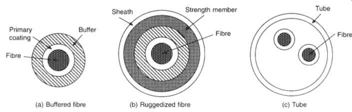
Fig. 12 Optical cable elements
(a) Duplex buffered fiber indoor cable
(b) 48 fire duct cable with tubed fibers
(c) 240 fire slotted-core cable for direct burial Fig. 13
Examples of optical cables
Although the same basic principles of cable construction are used, the wide range of applications results in a variety of cable designs, from simplex indoor patch cords to cables containing several thousand fibers for arduous environments, to sub-oceanic cables. Figure 13 shows just a few examples.
5.3 Interconnections
The satisfactory operation of a fiber optic system requires effective jointing and termination of the transmission medium, in the form of fiber-to-fiber splices and fiber connections to repeaters and end equipment. This is particularly important because with very low loss fibers the attenuation due to interconnections can be greater than that due to a considerable length of cable.
For all types of interconnection there is a loss, known as the insertion loss, which is caused by Fresnel reflection and by misalignment of the fibers.
Fresnel reflection is caused by the changes in refractive index at the fiber-air- fiber interface, but it can be minimized by inserting into the air gap an index- matching fluid with the same refractive index as the core.
Mis-alignment losses arise from three main sources as shown in Fig. 14.
Interconnection designs aim to minimize these losses. End-face separation (Fig. 14(a)) allows light from the launch fiber to spread so that only a fraction is captured by the receive fiber; this should therefore be minimized. Normally the fiber cladding is used as the reference surface for aligning fibers, and the fiber geometry is therefore important, even when claddings are perfectly aligned. Losses due to lateral misalignment (Fig. 14(b)) will therefore depend on the core diameter, non-circularity of the core, cladding diameter, non-circularity of the cladding and the concentricity of the core and cladding in the fibers to be jointed. Angular misalignment can result in light entering the receive fiber at such an angle that it cannot be accepted. It follows that very close tolerances are required for the geometry of the joint components and the fibers to be jointed, especially with single-mode fibers with core diameters of 8 pm and cladding diameters of 125 pm.
The main types of interconnections are fiber splices and demountable connectors.
Fiber splices are permanent joints made between fibers or between fibers and device pigtails. They are made by fusion splicing or mechanical alignment. Infusion splicing, prepared fibers are brought together, aligned and welded by local heating combined with axial pressure. Sophisticated portable equipment is used for fusion splicing in the field. This accurately aligns the fibers by local light injection and carries out the electric arc welding process automatically. Nevertheless, a level of skill is required in the preparation of the fibers, stripping the buffers and coatings and cleaving the fibers to achieve a proper end face. There are a number of mechanical techniques for splicing fibers which involve fiber alignment by close tolerance tubes, ferrules and v-grooves, and fixing by crimps, glues or resins. Both fusion and mechanical splicing techniques have been developed to allow simultaneous splicing of fibers which are particularly suitable for fiber ribbons. For a complete joint, the splices must be incorporated into an enclosure which is suitable for a variety of environments such as underground chambers or pole tops. The enclosure must also terminate the cables and organize the fibers and splices, and cassettes are often used where several hundred splices are to be accommodated.
Demountable connectors provide system flexibility, particularly at and within the transmission equipment and distribution panels, and they are widely used on patch cords in certain data systems. As with splices, the connector must minimize Fresnel and misalignment loss, but it must also allow for repeated connection and disconnection, it must protect the fiber end face and it must cater for mechanical stress such as tension, torsion and bending. Many designs have been developed, but in general the tolerances that are achievable on the dimensions of the various components result in a higher optical loss than in a splice. Demountable connectors have also been developed for multiple-fiber simultaneous connection, with array designs being particularly suitable for fiber ribbons. For connector-intensive systems such as office data systems, use is made of factory-predetermined cables and patch cords to reduce the need for on-site termination.
(a) End face separation
(b) Lateral misalignment
(c) Angular misalignment
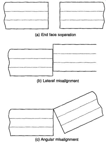
Fig. 14 Sources of misalignment loss
5.4 Installation
Optical fiber cables are designed so that normal installation practices and equipment can be used wherever possible, but as they generally have a lower strain limit than metallic cables special care may be needed in certain circumstances and manufacturer's recommendations regarding tensile loads and bending radii should be followed.
Special care may be needed in the following circumstances:
--because of their light weight, optical cables can be installed in greater lengths than metallic cables. For long underground ducts access may be needed at intermediate points for additional winching effort, and space should be allowed for larger 'figure 8' cable deployment.
--mechanical fuses and controlled winching may be necessary to ensure that the rated tensile load is not exceeded
-- guiding equipment may be necessary to avoid subjecting optical cables to unacceptable bending stresses, particularly
--when the cable is also under tension when installing cables in trenches the footing should be free from stones. These could cause microbending losses.
--in buildings, and particularly in risers, cleats and fixings should not be over-tightened, or appropriate designs should be used to prevent compression and the resulting microbending losses
-- indoor cable routes should provide turning points if a large number of bends is involved. Routes should be as straight as possible.
--excess lengths for jointing and testing of optical cables are normally greater than those required for metallic cables
where non-metallic optical cables are buried, consideration of the subsequent location may be necessary. Marker posts and the incorporation of a location wire may be advisable.
Blown fiber systems have been developed as a means of avoiding fiber overstrain for complex route installation and of allowing easy system upgrading and future proofing. It results in low initial capital costs and provides for the distribution of subsequent costs. Initially developed by British Telecom, the network infrastructure is created by the most appropriate cabling method, being one or a group of empty plastic tubes. As and when circuit provision is required, one or more fibers can be blown by compressed air into the tubes. Individual tubes can, by means of connectors, be extended within buildings up to the fiber terminating equipment. The efficient installation of fibers into the tube network often requires the use of specially designed fibers and equipment such as air supply modules, fiber insertion tools and fiber pay- offs. For installation it is necessary to follow the instructions provided by the supplier, taking into account the requirements for the use of portable electrical equipment and compressed air, and the handling, cutting and disposal of optical fibers. A novel variation of this system is a data cable used for structural wiring systems. In a 'figure-8' configuration one unit comprises a 4-pair data cable and the other an empty tube, so that when an upgrade is required to an optical system the appropriate fiber can be blown in without the need for re-cabling.
6. Standards
6.1 Metallic wires and cables
Most generally available cables are manufactured to recognized standards which may be national, European or international. Each defines the construction, the type and quality of constituent materials, the performance requirements and the test methods for the completed cable.
IEC standards cover those cables which need to be standardized to facilitate world trade, but this often requires a compromise by the parties involved in the preparation and acceptance of a standard. Where cables are to be used in a particular country, the practices and regulations in that country tend to encourage the more specific cable types defined in the national standards for that country. BS remains the most appropriate for use in the UK, and for the main cable types described in this Section reference has therefore been made mainly to the relevant BS.
Some cables rated at 450/750 V or less have through trade become standard throughout the EU, and these have been incorporated into Harmonization Documents (HDs). Each EU country must then publish these requirements within a national standard. A harmonized cable type in the UK for instance would still be specified to the relevant BS and the cable would, if appropriate, bear the <HAR> mark.
The key standards for metallic wires and cables which have been referred to in the Section are listed in Table 1.
Table 1 International and national standards for metallic wires and cables
6.2 Optical communication cables
For communication systems and their evolution to be effective, standardization must be at an international level. Optical fiber and cable standardization in IEC started in 1979. In Europe ENS have been published; these generally use the IEC standards as a starting point but they incorporate any special requirements for sale within the EU. Table 2 summarizes the main standards in the areas of optical fibers, optical cables, connectors, connector interfaces and test and measurement procedures for interconnecting devices.
Table 2 International and national standards for optical fibers, optical cables, connectors, connector interfaces and test and measurement procedures for interconnecting devices
6.2 Optical communication cables
For communication systems and their evolution to be effective, standardization must be at an international level. Optical fiber and cable standardization in IEC started in 1979. In Europe ENS have been published; these generally use the IEC standards as a starting point but they incorporate any special requirements for sale within the EU. Table 2 summarizes the main standards in the areas of optical fibers, optical cables, connectors, connector interfaces and test and measurement procedures for interconnecting devices.
Table 2 International and national standards for optical fibers, optical cables, connectors, connector interfaces and test and measurement procedures for interconnecting devices.