AMAZON multi-meters discounts AMAZON oscilloscope discounts
1. Introduction
Throughout the world, whether in underdeveloped areas or in highly developed countries, there is a need for generators in many different applications.
In addition to the underlying need for a public supply of electricity, there are a number of situations in which independent supplies are needed. The applications for generators are categorized broadly:
-- public supply networks in which a number of high-power generator sets may operate in parallel
-- private or independent generators which may run in parallel with the public supply or isolated from it. Examples of this include:
-- peak shaving to reduce the maximum demand of electricity by a user; this can avoid large financial penalties during times of generally high demand on the system
-- standby emergency generators to protect the supply to critical circuits such as hospitals or water supplies
-- temporary supplies which are needed by the construction industry, or in cases of breakdown
-- combined heat and power where the waste heat from the generator engine is used for other purposes such as building heating
-- portable supplies, often trailer-mounted, where no alternative supply is available
2. Main generator types
The two main types of generator are 'turbo' or cylindrical-rotor and salient-pole generators. Both these types are synchronous machines in which the rotor turns in exact synchronism with the rotating magnetic field in the stator. Since most generators are in this class, it forms the basis of most of the Section.
The largest generators used in major power stations are usually turbo-generators.
They operate at high speeds and are usually directly coupled to a steam or gas turbine.
The general construction of a turbo-generator is shown in Fig. 1. The rotor is made from solid steel for strength, and embedded in slots within the rotor are the field or excitation windings. The outer stator also contains windings which are located in slots, this is again for mechanical strength and so that the teeth between the slots form a good magnetic path. Most of the constructional features are very specialized, such as hydrogen cooling instead of air, and direct water cooling inside the stator windings, so only passing reference is made to this class of machine in the following descriptions.
More commonly used in smaller and medium power ranges is the salient-pole generator. An example is shown in Fig. 2. Here, the rotor windings are wound around the poles which project from the centre of the rotor. The stator construction is similar in form to the turbo-generator stator shown in Fig. 1.
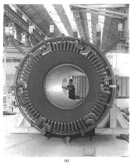
Fig. 1 Turbo-generator construction: (a) stator, (b) rotor, (c) assembly
Less commonly used are induction generators and inductor generators.
Induction generators have a simple form of rotor construction shown in Fig. 3, in which aluminum bars are cast into a stack of laminations. These aluminum bars require no insulation and the rotor is therefore much cheaper to manufacture and much more reliable than the generators shown in Figs. 1 and 5.2. The machine has characteristics which suit wind turbines very well, and they also provide a low-cost alternative for small portable generators. The basic action of the induction generator will be described later in this Section, but both the construction and the operation of the machine are very similar to the induction motor described in Section 10.
Inductor generators use solid steel rotors cut with slots to produce a flux pulsation in the stator as the rotor turns. These machines are usually used at high speed for specialized applications requiring high frequency.
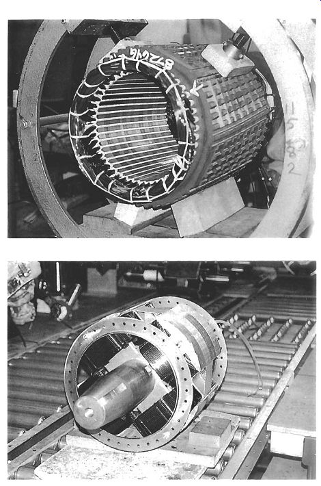
Fig. 2 Salient-pole generator construction: Top: stator, bottom: rotor
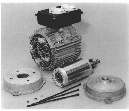
Fig. 3 Induction generator construction
3. Principles of operation
3.1 No-load operation
The basic operation of all these generator types can be explained using two simple rules, the first for magnetic circuits and the second for the voltage induced in a conductor when subjected to a varying magnetic field.
The means of producing a magnetic field using a current in an electric circuit have been explained in section 2.2.3, and eqs 2.13 and 2.18 have shown that the flux @ in a magnetic circuit which has a reluctance R, is the result of a magneto-motive force (mmf) F,, which itself is the result of a current Z flowing in a coil of N turns.
@ = F,,,IR, and F,,, = IN
The main magnetic and electrical parts of a salient-pole generator are shown diagrammatically in Fig. 4. In Fig. 4(a), dc current is supplied to the rotor coils through brushes and sliprings. The product of the current Z and the coil turns N results in mmf F, as in eqn 5.2, and this acts on the reluctance of the magnetic circuit to produce a magnetic flux, the path of which is shown by the broken lines in Fig.
4(b). As the rotor turns, the flux pattern created by the mmf F, turns with it; this is illustrated by the second plot of magnetic flux in Fig. 4(b). In section 2.2.3 it has also been explained that when a magnetic flux @ passes through a magnetic circuit with a cross-section A, the resulting flux density B is given by B = @IA (5.3)
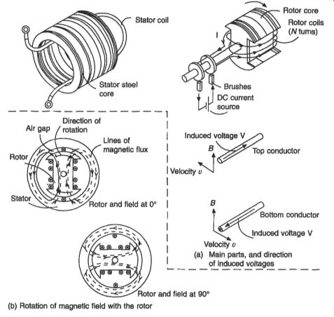
Fig. 4 Principles of generator operation --- (b) Rotation of magnetic
field with the rotor.
Figure 5.4(a) also shows a stator with a single coil with an axial length 1. As the rotor turns its magnetic flux crosses this stator coil with a velocity u. It has been explained in section 2.2.4 that an electromotive force (emf) V will be generated, where
V= Bul (5.4)
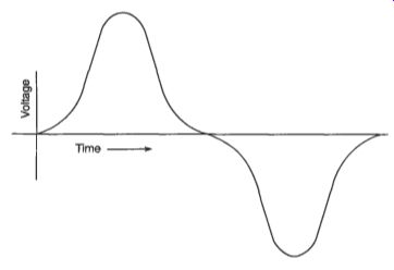
Fig. 5 Induced voltage waveform
The direction of the voltage is given by Fleming's right-hand rule, as shown in Fig. 2.6.
Figure 5.4(b) shows that as the magnetic field rotates, the flux density at the stator coil changes. When the pole face is next to the coil, the air gap flux density B is at its highest, and B falls to zero when the pole is 90" away from the coil. The induced emf or voltage V therefore varies with time (Fig. 5) in the same pattern as the flux density varies around the rotor periphery. The waveform is repeated for each revolution of the rotor; if the rotor speed is 3000 rpm (or 50 reds) then the voltage will pass through 50 cycle/s (or 50 Hz). This is the way in which the frequency of the electricity supply from the generator is established. The case shown in Fig. 4 is a 2-pole rotor, but if a 4-pole rotor were run at 1500 rpm, although the speed is lower, the number of voltage alternations within a revolution is doubled, and a frequency of 50 Hz would also result. The general rule relating the synchronous speed n, (rpm), number of poles p and the generated frequency f (Hz) is given by f = a,p/120 (5.5)
The simple voltage output shown in Fig. 5 can be delivered to the point of use (the 'load') with a pair of wires and this form of supply is known as single phase. If more coils are added to the stator shown in Fig. 4(a), and if these are equally spaced, then a three-phase output as shown in Fig. 6 can be generated. The three phases are conventionally labeled 'U', 'V' and 'W'. The positive voltage peaks occur equally spaced, one-third of a cycle apart from each other. The nature of single-phase and three-phase circuits has been explained in Section 2. The three coils either supply three separate loads, as shown in Fig. 7(a) for three electric heating elements, or more usually they are arranged in either 'star' or 'delta' in a conventional three-phase circuit (Fig. 7(b)).
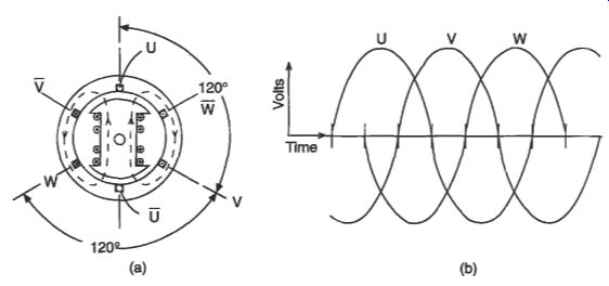
Fig. 6 Three-phase generation
In a practical generator the stator windings are embedded in slots, the induced voltage remaining the same as if the winding is in the gap as shown in Fig. 4(b). Also, in a practical machine there will be more than the six slots shown in Fig. 6(a). This is arranged by splitting the simple coils shown into several sub-coils which occupy separate slots, each phase still being connected together to form a continuous winding. Figures 1 and 2 show the complexity that results in a complete stator winding.
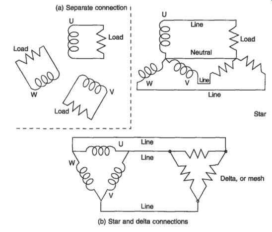
Fig. 7 Three-phase connections
3.2 The effect of load.
In the circuits shown in Fig. 7 currents flow in each phase, and these currents will have a waveform similar to the voltage waveform shown in Fig. 6(b). The concept of a phase shift between voltage and current in ac circuits which contain inductance or capacitance has been explained in section 2.3.2. If an inductive or capacitive load is connected, then the current waveforms will respectively 'lag' or 'lead' the voltage waveforms by 90". For the inductive load case shown in Fig. 6(a), the current in the U phase will be zero, but current will be flowing in V and W phases. It can be seen that the lines of magnetic flux now enclose not only the rotor excitation current, but also the stator currents in the V and W phases. Equations 5.1 and 5.2 show that the flux is the result of the mf acting on a magnetic circuit, but it can now be seen that the mmf is a combination of the ampere-turns from the rotor and the stator winding. If I,., I,, N,, and N, are the currents and turns in the stator and rotor windings respectively then eqns 5.1 and 5.2 combine to give
@ = (IrNr + IsNs)IRm (5.6)
In Fig. 6 a cross is used to indicate a current flow into the page, and a dot shows current flowing out of the page. It is seen that the stator currents oppose the excitation current in the rotor and their effect is to reduce the flux, with a corresponding reduction in the generated voltage. This demagnetizing effect is called 'armature reaction'; it is the way in which Lenz's law (section 2.2.4) operates in a generator.
The underlined currents in eqn 5.6 indicate that these are vectors and a vector addition is necessary. The armature reaction effect therefore depends on the extent to which the stator currents lag or lead the voltages (often called the 'phase' or 'phase angle'). If, for example, the generator load is capacitive, the currents will lead the voltages by 90". and they will be opposite in direction to that shown in Fig. 6 for an inductive load. The ampere-turns of stator and rotor windings will add in this case and the flux and the generated voltage will be higher. In the case of a resistive load, the ampere-turns of the stator will act at 90 deg. to the rotor poles, tending to concentrate the flux towards the trailing edge of the pole and producing magnetic saturation here when large stator currents flow; this reduces the flux and the output voltage, but not so much as in the inductive load case.
The output voltage is influenced not only by armature reaction, but also by voltage drop within the stator winding. This voltage drop is partly due to the internal resistance of the winding, and partly due to flux which links the stator winding but not the rotor winding; this flux is known as 'Zenkugeflid and it appears in the stator electrical circuit as a leakage inductance, which also creates a voltage drop. The phase angle between stator currents and voltages will affect this voltage drop, producing a greater drop at lagging currents, and a negative drop (an increase) in voltage at leading currents.
In order to maintain a constant output voltage it is therefore necessary to change the excitation current in the rotor to compensate for the load conditions. The variation in rotor current to do this is shown in Fig. 8.
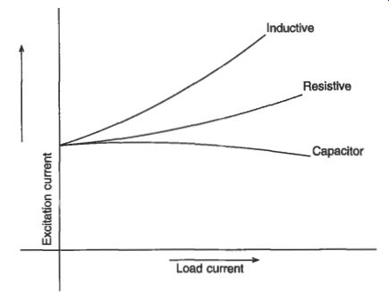
Fig. 8 Variation of excitation current with load current to maintain
constant output voltage
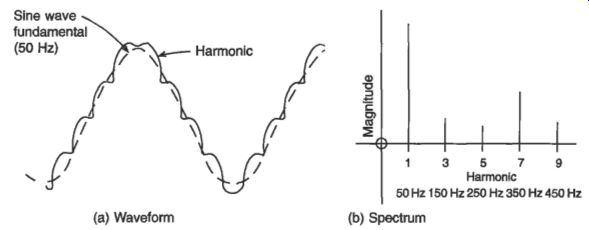
Fig. 9 Harmonic distortion
3.3 Damping of transients
Transient changes in stator load result in a change of flux in the rotor pole, and if it can be arranged that this flux change induces a voltage and a flow of current in the pole face, this current will oppose the change in stator flux. To achieve this, it is normal to insert into the pole face a set of aluminum or copper 'damper' bars, connected at either end by a ring or end plate to form a conducting cage in the pole faces.
The damper cage has a considerable influence on the transient current flow in the stator, particularly in the case of a short circuit. In addition, if the load in the three phases is unbalanced, the induced currents in the damper cage will act to reduce distortion of the waveform and to reduce asymmetry in the output phase voltages. A single-phase generator represents a severe case of asymmetry, and this requires very careful damper cage design because of the high induced currents.
The cage also helps to damp mechanical oscillations of the rotor speed about the synchronous speed when the generator is connected in parallel with other machines.
These oscillations might otherwise become unstable, leading to the poles 'slipping' in relation to the frequency set by other generators, and resulting in a loss of synchronism.
Such a condition would be detected immediately by the generator protection circuits and the generator would then be isolated from the network.
3.4 Voltage waveform
The specified voltage waveform for a generator is usually a sine wave with minimum distortion. A sine wave supply has advantages for many loads because it minimizes the losses in the equipment; this is especially the case with motors and transformers.
The voltage waveform of a practical generator usually contains some distortion or harmonics, as shown in Fig. 9. The distorted waveform shown in Fig. 9(a) can be represented as a series of harmonics, consisting of the fundamental required frequency and a series of higher frequencies which are multiples of the fundamental frequency.
The harmonic distortion is calculated using a Fourier analysis or other means of obtaining the spectrum of harmonics. An example of a spectrum is shown in Fig. 9(b). Distortion is defined by a 'distortion factor', where
(5.7)
Distortion factor = (E V;)lnIV,
In eqn 5.7, V, is the magnitude of the nth harmonic, VI being the magnitude of the fundamental.
There are several ways in which a generator can be designed to produce minimum distortion factor.
The higher frequency “slot harmonics” are due to distortions in the air gap flux density wave, these being created by the stator slot openings. The distortions can be reduced by skewing the stator slots so that they are no longer parallel to the rotor shaft, but form part of a helix. The slots are often skewed by an amount close to the pitch between one stator slot and the next.
A second step is to use more than one stator slot per pole for each phase winding; Fig. 10 shows a winding with three stator slots per pole for each phase. This distributes the effect of the winding better and reduces the harmonics.
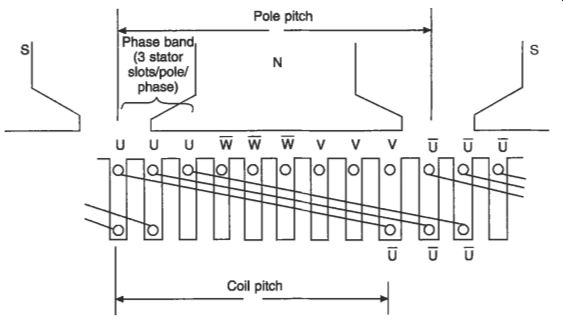
Fig. 10 Slot and winding layout
Harmonics can also be reduced by 'short-pitching' the stator winding as shown in Fig. 10. Except for the smallest machines, most generators have a double layer winding in which the one side of a coil is laid into a slot above the return side of a different coil. The simplest (fully pitched) winding has all the coil sides of one phase in slots above the return sides of coils in that same phase, but by displacing one layer of the winding with respect to the other, the harmonics are reduced.
A fourth technique is to shape the face of the rotor pole so that the air gap between rotor and stator is larger at the tips. This prevents a 'flat-topped' shape to the flux wave in the air gap and therefore reduces voltage distortion.
Finally, correct spacing of the damper bars in the pole face and proper choice of the arc length of the pole face reduces the high frequency harmonics which are produced by currents induced in the bars by the passage of the stator slots.
4. The Automatic Voltage Regulator (AVR)
While some small generators have an inherent ability to produce reasonably constant voltage as the load varies, it is clear from the previous explanations that some form of automatic voltage control is required in the usual form of generator. This control is referred to as an automatic voltage regulator, or AVR, and it is based on a closed- loop control principle.
The basis of this closed-loop control is shown in Fig. 11. The output voltage is converted, usually through a transformer or resistor network, to a low voltage dc signal, and this 'feedback' signal is subtracted from a fixed 'reference' voltage to produce an 'error' signal.
The error signal is processed by a 'compensator' before being amplified to drive the rotor excitation current. The change in rotor excitation current produces a variation in output voltage, closing the control loop. If the 'gain' of the control loop is large enough then only a small error is required to produce the necessary change in excitation current and the output current will therefore remain substantially constant.
A high gain can lead to instability in the circuit, with oscillations in the output voltage; the purpose of the compensating circuit is to enable small errors to be handled in a stable way. The most common form of compensator is a PID circuit in which the error is amplified proportionately (P), integrated (I) and differentiated (D) in three parallel circuits before being added together. Many AVRs have adjustment potentiometers which allow the gains of each channel to be varied in order to achieve the best performance. The integral term enables compensator output to be achieved at zero error, and this produces the minimum error in output voltage.
The layout of a commercial AVR is shown in Fig. 12.

Fig. 11 Closed-loop voltage control
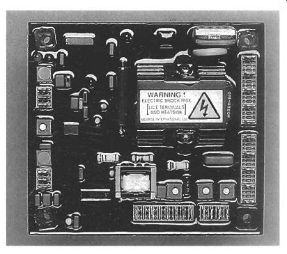
Fig. 12 Layout of an automatic voltage regulator (AVR)
Many AVRs are now offered with digital circuitry. The principle of the feedback loop remains the same, but the feedback signal is converted to digital form using an analogue to digital converter. The calculations are performed digitally in a microprocessor and the output is on or off, using pulse width modulation (PWM) to vary the average level of dc supplied to the rotor excitation winding. Alternatively, the phase angle of a thyristor bridge can be used to vary the output level; this is known as phase-angle control.
The continuous improvement in power electronic controls and processor power is bringing further advances in voltage and speed control, with more flexible protection of the generator and its connected circuits. An example of recent developments is the variable-speed constant-frequency generator from Generac Corporation; this is illustrated in Fig. 13. This consists of an variable-speed engine-driven permanent- magnet generator feeding a power electronic frequency-changer circuit, the output being at constant 50 Hz or 60 Hz frequency. A microprocessor is used to control the switching of the output devices and to regulate the engine speed depending upon the load applied to the generator. At low power demand the engine speed is reduced to minimize noise, increase efficiency and extend life expectancy. The result is a saving in the volume and weight of the generator.
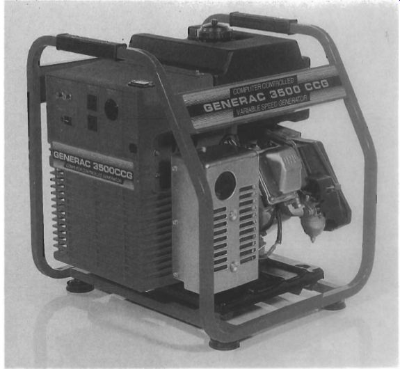
Fig. 13
Variable-speed constant-frequency generator
5. Brushless excitation
Although some generators are still produced with brushes and sliprings to provide the rotor current as illustrated in Fig. 4, most now have a brushless excitation system. The two main techniques for synchronous generators are the separate exciter and capacitor excitation and these are described in the following sections. Also included for convenience here is a brief description of induction generators, since these also provide a brushless system.
5.1 Separate exciter
The most common way of supplying dc current to the rotor winding without brushes and sliprings is shown in Fig. 14.
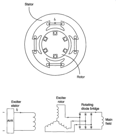
Fig. 14 Separate brushless exciter
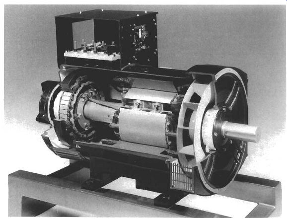
Fig. 15 Cut-away section of an ac generator
The output of the AVR drives a dc current If through the poles of the exciter, which are mounted in a stator frame. The stator then produces a stationary flux which induces a voltage in the rotor winding as it turns. Figure 5.15 shows that the exciter rotor is mounted on the same shaft as the main generator. The ac voltage produced by the rotor winding of the exciter is converted to dc by a bridge rectifier which is also mounted on the rotor shaft. This rectifier unit is shown clearly at the end of the shaft in Fig. 18. The dc output of the rectifier is connected to the main rotor windings by conductors laid in a slot along the rotor shaft. The inductance of the main generator rotor coils is usually sufficient to smooth out the ripple in the bridge rectifier output.
The power supply to the AVR is either provided by a separate excitation winding in the main generator stator, or by a small permanent-magnet generator mounted on the shaft of the main generator. This is often referred to as a 'pilot exciter'. The advantage of the pilot exciter is that the generator has a source of power available once the shaft is turning; the voltage supplied to the AVR is completely independent of generator load and there is no reliance on residual magnetism to start the self- excitation process. The first method relies on residual flux in the magnetic circuit of the main generator to start self-excitation.
The pilot exciter also enables the generator to supply current to the connected network even when a short-circuit occurs, enabling the high current to be detected by protection relays which will then disconnect the faulty circuit. If the AVR is supplied from an excitation winding in the main generator stator, the supply voltage is very small when the stator windings experience a short-circuit, and the AVR is unable to drive an adequate rotor excitation current.
One manufacturer uses two excitation windings to provide a voltage from the AVR in short-circuit conditions, so that sufficient current is supplied into the fault to trip the protection system. During a short circuit the air gap flux density in these machines shows a pronounced third harmonic component. This component induces voltage in coils of one of the excitation windings, which are one-third pitched and this therefore delivers a voltage to the AVR under short-circuit conditions. The second excitation winding is fundamental-pitched and provides the major drive for the AVR under normal operating conditions. It is claimed that the performance of this system is comparable to a machine using a permanent-magnet exciter.
Another method used to provide voltage to the AVR under short-circuit conditions is a series transformer driven by the generator output current.
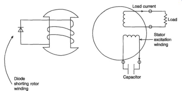
Fig. 16 Capacitor excitation
5.2 Capacitor excitation
The use of this technique is usually restricted to single-phase generators with a rated output less than 10 kW.
A separate excitation winding in the stator has a capacitor connected directly across its output as shown in Fig. 16. The rotor is usually of salient-pole construction as described previously, but in this case the rotor winding is shorted through a diode.
During starting, residual flux in the rotor body induces a small voltage in the stator excitation winding and a current flows through the capacitor. This current produces two waves of magnetic flux around the air gap of the generator. One wave travels in the same direction as the rotor, to create the armature reaction described in sub-section 3.2. The second wave travels in a direction opposite to the rotor, and induces a voltage in the rotor windings at twice output frequency. The current circulated in the rotor windings by this induced voltage is rectified by the diode to produce a dc current. This dc current increases the magnetic flux in the machine, which in turn drives more current through the stator excitation winding, which in turn produces more rotor current. This self-excitation process continues until the flux reaches a point at which the magnetic circuit is saturated, and a stable voltage results. The process also produces an inherent AVR action, since any load current in the output stator winding induces more rotor current to offset the armature reaction effect.
5.3 Induction generator
The principles and construction of the cage induction motor are explained in Section 10. If a three-phase motor of this type is energized, it will accelerate as a motor up to a speed near its synchronous speed. As shown in eqn 5.5, the synchronous speed for a 4-pole machine operated at 50 Hz would be 1500 rpm. If the machine is driven faster than the synchronous speed by an engine or other prime mover, the machine torque reverses and electrical power is delivered into the connected circuit.
A simple form of wind turbine generator uses an induction machine driven by the wind turbine. The induction machine is first connected to the three-phase supply, and acting as a motor it accelerates the turbine up to near the synchronous speed. At this point, the torque delivered by the wind turbine is sufficient to accelerate the unit further, the speed exceeds the synchronous speed and the induction machine becomes a generator.
It is also possible to operate an induction machine as a generator where there is no separate mains supply available. It is necessary in this case to self-excite the machine, and this is done by connecting capacitors across the stator winding as shown in Fig. 17(a). The leading current circulating through the capacitor and the winding produces a travelling wave of mmf acting on the magnetic circuit of the machine. This travelling wave induces currents in the rotor cage which in turn produce the travelling flux wave necessary to induce the stator voltage. For this purpose, some machines have a excitation winding in the stator which is separate from the main stator output winding. Figure 5.17(b) shows a single-phase version of the capacitor excitation circuit.
Fig. 17 Self-excitation of an induction generator: (a) three phase (b) single phase In small sizes, the induction generator can provide a low-cost alternative to the synchronous generator, but it has relatively poor performance when supplying a low power factor load.
6. Construction
6.1 Stator
The stator core is constructed from a stack of thin steel sheets or laminations which are stamped to shape and insulated electrically from each other. either by a thin coating or by an oxide layer which is produced during heat treatment. The steel used has a small silicon content as described in Section 3; this increases the resistivity of the steel and therefore reduces the losses due to eddy currents. The steel is carefully processed in order to minimize the hysteresis losses because the whole stator core is subjected to alternating magnetic flux. In large turbo-generators the core is built up in segments and grain-oriented steel is used to reduce the losses further.
The stator windings are located in axial slots in the stator core which are formed by the shape of the laminations. Except in high voltage machines, the individual coils of the winding are wound with copper wire covered with a layer of polyester/polyamide enamel which is about 0.05 mm thick. The slots are lined with a tough insulating sheet, usually about 0.25-0.5 mm thick; a popular material is a laminate of Mylar and Nomex. The coils are impregnated when in place with a resin to give the winding mechanical strength as well as to improve the heat transfer from the copper to the cooling air. Windings operating at different voltages, such as the three phases, have a further sheet of insulating material separating them in the end-winding region. A general guide to the insulation materials and processes in use is given in Section 3.
The mounting of the stator core in its frame differs according to the size of the machine, but in the majority of medium-sized generators the arrangement is as shown in Fig. 15. At either end of the frame are bearing housings which locate the rotor shaft. These housings or end-bells are cast in smaller and medium size machines, and fabricated in larger sizes. The generator is often mounted directly onto the engine, and in this case it is usual to eliminate the drive-end bearing and to use the rear bearing of the engine to locate the generator shaft.
6.2 Rotor
It has already been noted that the construction of a turbo-generator is very specialized and the rotor for these machines is not dealt with here. However, even within the class of salient-pole generators, quite different forms of rotor construction are used, depending upon size.
Generators rated up to about 500 kW use rotor laminations which are stamped in one piece. In larger machines the poles are made separately from stacks of laminations, and each pole is keyed using a dovetail arrangement onto a spider which is mounted on the rotor shaft. In large high-speed machines the poles can be made from solid steel for extra strength and to reduce mechanical distortion; these solid poles are screwed to the shaft, as shown in the large 4-pole machine in Fig. 18.
The nature of the rotor coils also depends upon the size of the machine. Because the ratio of surface area to volume is larger in the coils of small generators, these are easier to cool. Generators rated above about 25 kW therefore use a 'layer-wound' coil in which each layer of the coil fits exactly into the grooves formed by the layer below; this is illustrated in Fig. 19. Rectangular cross-section wire can be used to minimize the coil cross-section. The simplest and cheapest way to make the coils, often used in smaller machines, is to wind them in a semi-random way as shown in Fig. 20. In either case, the coils are impregnated after winding like the stator windings to give extra mechanical strength and to improve the heat transfer by removing air voids within the coil.
The coils are under considerable centrifugal stress when the rotor turns at full speed, and they are usually restrained at both ends of the pole by bars, and by wedges in the interpole spaces, as shown in Fig. 18.
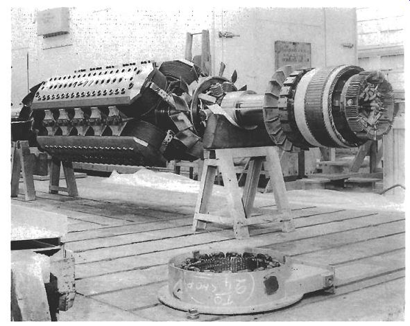
Fig. 18 Large salient-pole rotor
6.3 Cooling
Adequate cooling is a vital part of the design and performance of a generator. Forced cooling is needed because of the high loss densities that are necessary to make economic use of the magnetic and electrical materials in the generator.
The most critical areas in the machine are the windings, and particularly the rotor winding. It is explained in Section 3 that the life expectancy of an insulation system decreases rapidly if its operating temperature exceeds recommended temperatures. It is crucial for reliability therefore that the cooling system is designed to maintain the winding temperatures within these recommended limits. As shown in Table 3.4, insulation materials and systems are defined by a series of letters according to their temperature capability. As improved insulation with higher temperature capability has become available, this has been adopted in generator windings and so the usual class of insulation has progressed from class A (40-50 years ago) through class E and class B to class F and class H, the latter two being the systems generally in use at present. Class H materials are available and proven, and this system is becoming increasingly accepted. An important part of the generator testing process is to ensure that the cooling system maintains the winding temperature within specified limits, and this is explained later in sub-section 8.
In turbo-generators it has already been noted that very complex systems using hydrogen and de-ionized water within the stator coils are used. The cooling of small and medium-sized machines is achieved by a flow of air driven around the machine by a rotor-mounted fan.
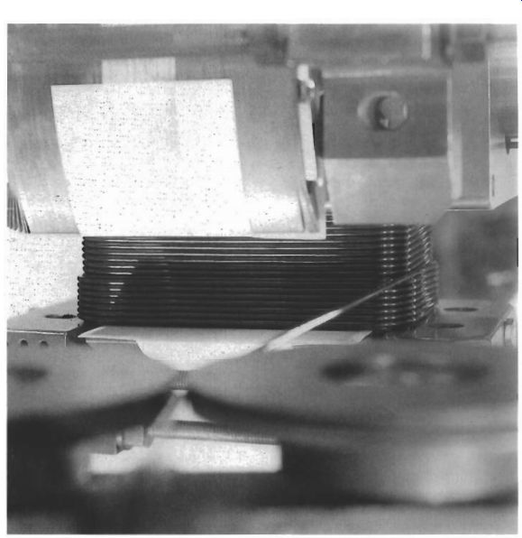
Fig. 19 Layer-wound rotor
A typical arrangement is shown in Fig. 15. In this case the cooling air is drawn in through ducts; it is then drawn through the air gap of the machine and ducts around the back of the stator core before reaching the centrifugal fan which then expels the air from the machine. There are many variations to the cooling system, particularly for larger generators. In some machines there is a closed circulated air path cooled by a secondary heat exchanger which rejects the heat to the outside atmosphere. This results in a large and often rectangular generator enclosure as shown in Fig. 21.
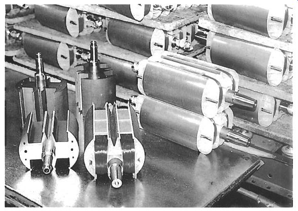
Fig. 20 Random-wound rotors
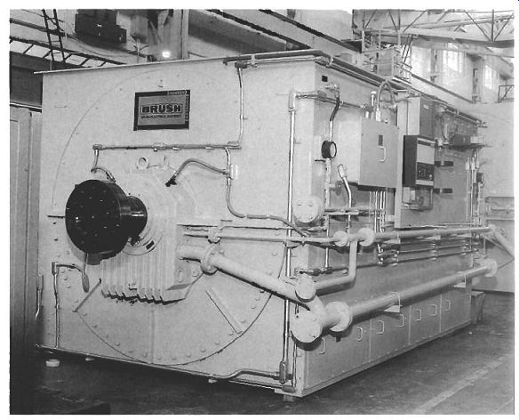
Fig. 21 Closed air circuit cooled generator
7. Rating and specification
In order that a generator can be selected to suit a particular application, manufacturers issue specification data. This can be used and interpreted according to the following sections.
7.1 Rated output
The key aspect of the specification is the rated output of the generator, which is normally expressed in terms of the apparent power (VA, kVA or MVA) when supplying the maximum load at the rated power factor, assumed to be 0.8. The rated output is usually based upon continuous operation in a maximum ambient temperature of 40°C. If the machine has a special short-time rating the nameplate should state the time limits of operation.
The rated output from a given size of generator is related to the size and speed of the machine:
Rated output power = K x Di x L, x n, (5.8)
... where Dg is the stator bore diameter, L, is the stator core length and n, is the speed.
K is a design constant which is proportional to the product of the air gap flux density and the stator current density.
The rated output of a machine is reduced in ambient temperatures exceeding 40°C and at altitudes above sea level exceeding 1000 m. The latter is because the air density is decreased, and its ability to cool the machine is reduced. Derating factors are applied for these conditions and typical values are summarized in Tables 1 and 2.
Table 1 Typical derating factors for class H insulation in ambient temperatures above 40°C Table 2 Typical altitude derating factors
7.2 Reactances
The generator can be characterized by several reactances, each being useful in working out the performance and protection requirements under different circumstances. These include the synchronous reactance, the transient reactance, the subtransient reactance, the Potier reactance and the negative- and zero-sequence reactances.
The subtransient reactance represents the output impedance of the generator within the first few cycles after a short-circuit occurs at the generator terminals. It is used for selecting protective relays for the connected load circuit. The lower the value of the subtransient reactance, the more onerous is the protection requirement.
Transient reactance represents the impedance of the machine over a slightly longer period, and is relevant to the performance of the generator and its AVR under changing load conditions. A low transient reactance is beneficial in responding to load changes.
Associated with the subtransient and transient reactances are time constants which define the rate of decay of these reactances.
The negative and positive sequence reactances influence the performance of the generator when supplying an unbalanced three-phase load.
7.3 Main items of specification
In summary, the following items are important when considering an application and specifying the appropriate generator:
rated output, expressed as apparent power (VA)
cooling air requirement (m^3/s)
moment of inertia of the rotor
generator weight
efficiency at full, 3/4, 1/2 and 1/4 load
stator winding resistance
reactances and time constants, as listed in sub-section 7.2
maximum short-circuit current delivered by the generator
Typical values for a 200 kW generator are shown in Table 3.

Table 3 Typical parameters for a 200 kW generator
8. Testing
Type tests are performed by manufacturers in order to confirm that a design meets its specifications, and production tests are done in order to check that each machine as it is manufactured conforms to performance and safety standards.
These tests usually include:
--full-load tests to measure the temperature rise of the machine windings and insulation. The temperature rise is calculated from the change in resistance of the stator windings.
--tests to determine the excitation current required to deliver a given output voltage. These are done for open-circuit conditions and also for various load currents and power factors. The resulting curves are usually known as 'saturation' curves.
--short-circuit tests to determine the current that can be driven by the generator into a short-circuit fault in the connected load
--transient short-circuit rests to determine the subtransient and transient reactances and time constants
--overspeed tests to confirm that the rotor does not distort or disintegrate. This test is normally performed at 150 per cent of rated speed, at full rated temperature.
The results from these tests are used to calculate the data described in sub-section 7, an example of which has been shown in Table 3.
It is now necessary for any generator manufactured or imported into the European Union that relevant EU Directives are met through certification. Strictly it is the manufacturer of the generator set, including the engine and all controls, that is responsible for this certification, but many manufacturers of generators and AVRs will assist in the tests.
9. Standards
The leading international, regional and national standards adopted by users and suppliers of generators for manufacturing and testing are shown in Table 4.

Table 4 International, regional and national standards relating to generators