AMAZON multi-meters discounts AMAZON oscilloscope discounts
1. Principles of operation
In simple form, a transformer consists of two windings connected by a magnetic core. One winding is connected to a power supply and the other to a load. The circuit containing the load may operate at a voltage which differs widely from the supply voltage, and the supply voltage is modified through the transformer to match the load voltage.
In a practical transformer there may be more than two windings as well as the magnetic core, and there is the need for an insulation system and leads and bushings to allow connection to different circuits. Larger units are housed within a tank for protection and to contain oil for insulation and cooling.
In the simplest case, with no load current flowing, the transformer can be represented by two windings on a common core, as shown in Fig. 1. It has been explained in Section 2 (eqns 2.25 and 2.26) that the input and output voltages and currents in a transformer are related by the number of turns in these two windings, which are usually called the primary and secondary windings. These equations are repeated here for convenience.
Vi/ V, = NlIN2 (eqn. 1)
IilIz = N2INl (eqn. 2)
VllN1 = 4.44jBJ (eqn. 3)
The magnetic flux density in the core is determined by the voltage per turn: In the no-load case, a small current Io flows to supply the magnetomotive force which drives the magnetic flux around the transformer core; this current lags the primary voltage by almost 90 deg. Io is limited in magnitude by the effective resistance (R,) and reactance (X,) of the magnetizing circuit, as shown in Fig. 2. The magnetizing current is typically 2 percent to 5 per cent of the full load current and it has a power factor in the range 0.1 to 0.2.
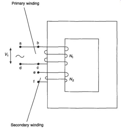
Fig. 1 Simple transformer circuit
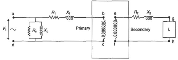
Fig. 2 Equivalent circuit of a transformer
When the transformer is loaded, there is an internal voltage drop due to the current flowing through each winding. The voltage drops due to the primary and secondary winding resistances (R1 and R2) are in phase with the winding voltage, and the voltage drops due to the primary and secondary winding leakage reactances (X1 and X2) lag the winding voltage by 90 deg. The leakage reactances represent those parts of the transformer flux which do not link both windings; they exist due to the flow of opposing currents in each winding and they are affected strongly by the winding geometry.
The current flow and voltage drops within the windings can be calculated using the equivalent circuit shown in Fig. 2. This circuit is valid for frequencies up to 2 Hz. A vectorial representation of the voltages and currents is shown in Fig. 3 for the case of a load L with a power factor angle @. The decrease in output voltage when a transformer is on load is known as regulation.
The output voltage is less than the open-circuit voltage calculated according to eqn 1 because of voltage drops within the winding when load current flows through the resistive and reactive components shown in Fig. 2. The resistive drops are usually much smaller than the reactive voltage drops, especially in large transformers, so the impedance Z of the transformer is predominantly reactive. Regulation is usually
112
Transformers R = R1 + R2(Nl/N*)' x = x, + X2(N1/N2)2 and
The impedance of the transformer is given by:
z = [R2 -J- x2y (eqn. 7)
Values for Rr and R2 can be established by measuring the resistance of the windings.
The value of X is determined by calculation or by derivation from the total impedance Z, which can be measured with one winding of the transformer short-circuited. Z is given by
z = VII (eqn. 8)
... where V is the voltage necessary to circulate the full-load current I in the windings under short-circuit conditions. When Vis expressed as a percentage of rated voltage, this gives Z as a percentage value referred to rated power.
When the transformer is energized, but without a load applied, the no-load power loss is due to the magnetic characteristics of the core material used and the flow of eddy currents in the core laminations. The loss due to magnetizing current flowing in the winding is small and can be ignored.
When the transformer is loaded, the no-load loss is combined with a larger component of loss due to the flow of load current through the winding resistance. Additional losses on load are due to eddy currents flowing within the conductors and to circulating currents which flow in metallic structural parts of the transformer. The circulating currents are induced by leakage flux which is generated by the load current flowing in the windings and they are load dependent. These additional losses are known as sway losses.
The efficiency of a transformer is expressed as:
Efficiency = (output/input) x 100%
= (input - 1osses) input x 100%
= [l - (lossed input)] x 100% (eqn. 9)
... where input, output and losses are all expressed in units of power.
The total losses consist of the no-load loss (or iron loss) which is constant with voltage and the load loss (or copper loss) which is proportional to the square of load current. Total losses are usually less than 2 per cent for distribution transformers, and they may be as low as 0.5 percent in very large transformers.
No-load and load losses are often specified as target values by the user for larger transformers, or they may be evaluated by the capitalization of losses. The capitalization formula is of the type:
C, = CT+ A X Po + B X PK (eqn. 10)
where C, = capitalized cost
CT = tendered price
A = capitalization rate for no-load loss (mW)
Po = guaranteed no-load loss (kW)
B = capitalization rate for load loss (EkW)
PK = guaranteed load loss (kW)
2. Main features of construction
2.1 The core
The magnetic circuit in a transformer is built from sheets or laminations of electrical steel. Hysteresis loss is controlled by selecting a material with appropriate characteristics, often with large grain size. Eddy current loss is controlled by increasing the resistivity of the material using the silicon content, and by rolling it into a very thin sheet. The power loss characteristics of available materials are shown in Fig. 5. Generally speaking the steels with lower power loss are more expensive, so that the 0.3 mm thick CGO steel shown is the cheapest of the range shown in Fig. 5, and the very low loss 0.23 mm thick Hi-B material with domain control techniques used to modify the apparent crystal size is the most expensive. New materials with thicknesses of 0.1 mm are available on a laboratory basis, but the use of such thin materials presents some production problems. The 25 pm thick amorphous ribbon shown with very low loss is made using a rapid cooling technique; it can be used in very low loss transformers up to a few MVA and a core with losses of only one-sixth of the conventional 0.3 mm CGO material is possible. The general principles applying to electrical steels are discussed in Section 3.
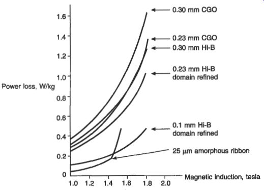
Fig. 5 Power loss characteristics of various electrical steels and amorphous
materials at 50 Hz The audible sound radiated by a transformer is generated
by magnetostrictive deformation of the core and by electromagnetic forces
in the windings, tank walls and magnetic shields. The dominant sound is
generated by longitudinal vibrations in the core laminations, which are
induced by the magnetic field. The amplitude of the vibrations depends
upon the flux density in the core and on the magnetic properties of the
core steel. In a large power transformer operating at high flux density
the audible sound level can exceed 100 dB(A) and it may be necessary to
use high quality core material, improved core-joint techniques and perhaps
external cladding or a sound enclosure to reduce the sound to an acceptable
level.
In small power transformers, the core may take the form of a continuous strip of steel wound into a coil. The windings may be formed directly onto this core using toroidal winding machines, or the core may be cut to allow preformed windings to be fitted, and re-interlaced with the windings in place.
Where transformer weight is critical, it may be advantageous to operate a local power system at high frequency. Equation 3 relates voltage per turn to frequency and core cross-section. If the system is designed to operate at 400 Hz (a typical requirement for aircraft), it can be seen that the core cross-section will be only 12.5 percent of that which would be necessary at 50 Hz. The clear advantage in cost and weight must be balanced against higher core losses at the increased frequency (although these can be reduced by using thinner laminations) and against higher load losses caused by high-frequency currents in the windings.
A longer-established form of construction uses the stacked-core technique. For transformers which are rated in hundreds of watts the laminations may be stamped in E and I shapes, or in C and I shapes, then built into cores and assembled round the windings. At higher ratings in kVA or MVA, the usual construction is to cut laminations to length, and to assemble them in a building berth which includes part of the core-clamping structure. When the core has been built, the remaining part of the clamping structure is fitted and the core is turned upright. If it has been fitted during the stacking stage, the top yoke is then removed, the windings are mounted on the core and the top yoke is then re-interlaced.
Single-phase transformers usually have a three-leg core with high-voltage and low-voltage windings mounted concentrically on the center leg to reduce leakage flux and minimize the winding impedance. The outer legs form the return path for the magnetizing flux. This type of construction is shown in Fig. 6(a). For very high ratings in the region of 500 MVA, it may be economic to use a two-leg construction with two sets of windings connected in parallel and mounted one on each leg, as shown in Fig. 6(b). Where a transport height limit applies, a large single-phase transformer may be mounted on a four-leg core where the outer legs are used to return remnant flux, in conjunction with smaller top and bottom yokes. This arrangement is shown in Fig. 6(c). Three-phase transformers are also based usually on a three-leg construction. In this case the high-voltage and low-voltage windings of each phase are mounted concentrically with one phase on each of the three legs. The phase fluxes sum to zero in the top and bottom yokes and no physical return path is necessary. This arrangement is shown in Fig. 6(d). Where transport heights are a limitation, a three-phase transformer may be built using a five-leg construction as shown in Fig. 6(e). The yoke areas in this case are reduced and the outer legs are included as return flux paths.
Core laminations are compacted and clamped together using yoke clamps connected by flitch plates on the outer faces of the legs, or by tie-bars locking the top and bottom yoke clamps together. Figure 7 shows a large three-phase, three-leg core in which the yokes are clamped by rectangular-section steel frames and insulated straps; flitch plates lock the two clamps together and the core-bands on the legs are temporary, to be removed when the windings are fitted.
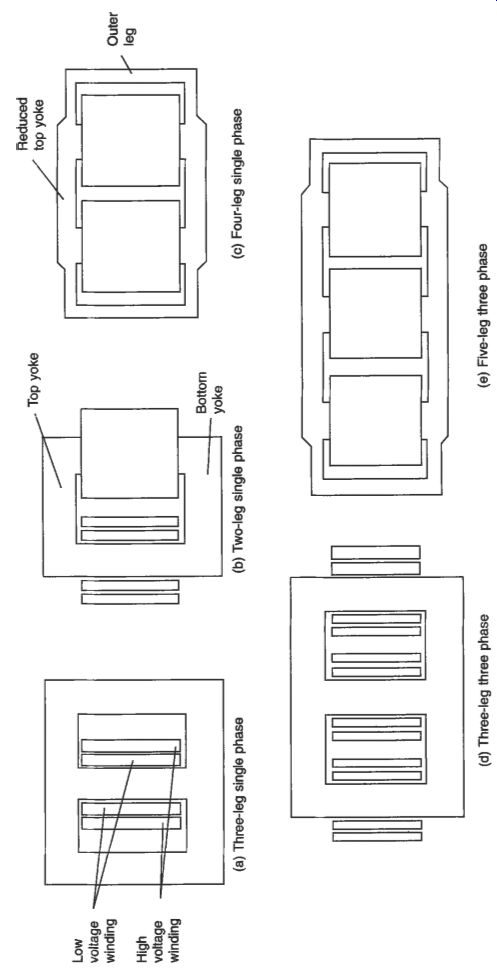
Fig. 6
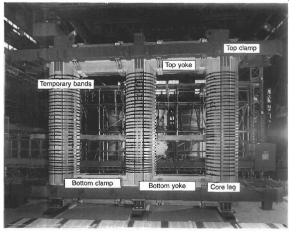
Fig. 7 Three-leg core for a three-phase transmission transformer
2.2 Windings
Winding conductors may be of copper or aluminum, and they may be in foil or sheet form, or of round or rectangular section. Foil or sheet conductors are insulated from each other by paper or Nomex interleaves, whereas round or rectangular conductors may be coated with enamel or wrapped with paper or some other solid insulation covering.
Low-voltage windings for transformers with ratings up to about 4 MVA may use foils with the full width of the winding, or round conductors. For higher-power transformers a large cross-section may be necessary to carry the current in the low-voltage winding, and it may be economic to use stranded or parallel conductors in order to reduce eddy currents. It may also be necessary to transpose conductors during the winding operation to reduce circulating currents within the winding. For very high current applications, continuously transposed conductor (CTC) may be used, where typically 40 or 50 conductors are machine transposed as shown in Fig. 8. In a CTC, each strand is enamel insulated and the cable is enclosed in a paper covering. The conductors for low-voltage windings are usually wound in layers, with cooling ducts and interlayer insulation as part of the construction.
High-voltage windings have more turns and carry less current than the low-voltage windings. They are usually formed from round enameled wire or paper-wrapped rectangular conductors. As with low-voltage windings, if the winding loss is to be minimized, parallel conductors or CTC may be used. The conductors are wound in layers or in discs, as shown in Figs 6.9(a) and 6.9(b) respectively. The labor cost in a layer winding is high, and disc windings are usually considered to be more stable mechanically under the effects of through-current faults.
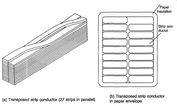
Fig. 8 Continuously transposed conductor. (b) Transposed strip conductor
in paper envelope (a) Transposed strip conductor (27 strips in parallel)
Although simple two-winding transformers are widely used, many transformers have three or more windings. These may include regulating windings, tertiary windings to balance harmonic currents or supply auxiliary loads, multiple secondary windings to supply separate load circuits, or multiple primary circuits to connect to power supplies at different voltages or frequencies. The constructional aspects are common between multiple windings, but design aspects are more complicated.
2.3 Winding connections
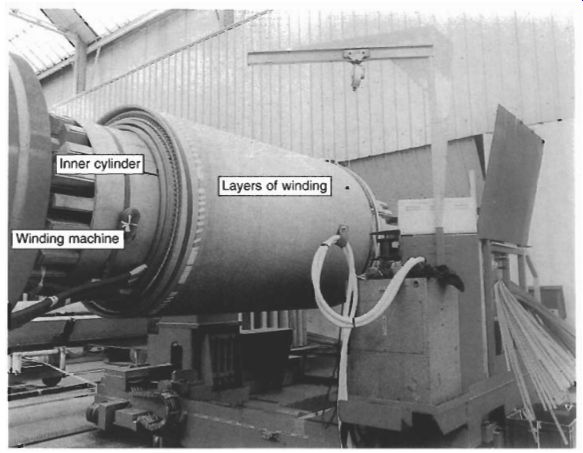
Fig. 9(a) Layer-type winding on a horizontal winding machine Fig. 9(b)
Disc-type winding on a vertical winding machine
Three-phase transformers are usually operated with the high-voltage and low-voltage windings connected in Y (star), D (delta) or 2 (zigzag) connection. The three styles are shown in Fig. 10.
In star connection, one end of each of the three-phase windings is joined together at a neutral point N and line voltage is applied at the other end; this is shown in Fig. 10(a). The advantages of star connection are: it is cheaper for a high-voltage winding the neutral point is available earthing is possible, either directly or though an impedance a reduced insulation level (graded insulation) is possible at the neutral winding tappings and tapchanger may be located at the neutral end of each phase, with low voltages to earth and between phases single-phase loading is possible, with a neutral current flowing In delta connection, the ends of the three windings are connected across adjacent phases of the supply as shown in Fig. 10(b). The advantages of a delta connection are:
it is cheaper for a high-current low-voltage winding
in combination with a star winding, it reduces the zero-sequence impedance of that winding
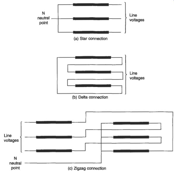
Fig. 10 Three-phase winding connections
The zigzag connection is used for special purposes where two windings are available on each leg and are interconnected between phases as shown in Fig. 10(c). The advantages of a zigzag connection are: it permits neutral current loading with an inherently low zero-sequence impedance, and it is used in 'earthing transformers' to create an artificial neutral terminal on the system voltage imbalance is reduced in systems where the load is not evenly distributed between phases In order to define the range of possible connections, a designation has been adopted by EC in which the letters Y, D, Z and N are assigned to the high-voltage windings and y, d, z and n are assigned to the low-voltage windings. Clock-hour designations 1 to 12 are used to signify in 30 degree steps the phase displacement between primary and secondary windings. YyO is the designation for a star-star connection where primary and secondary voltages are in phase. Ydl is the designation for a star-delta connection with a 30" phase shift between primary and secondary voltages. The common connections for three-phase transformers are shown in Fig. 11.
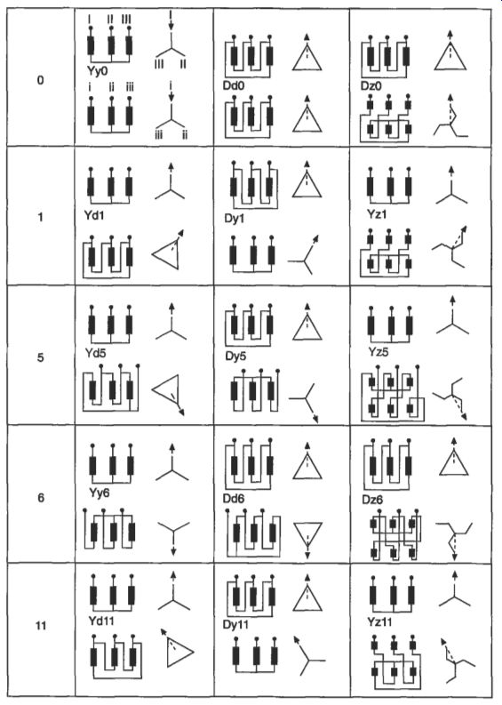
Fig. 11 Clock-hour designation of three-phase winding connections (based
on IEC 60076-1)
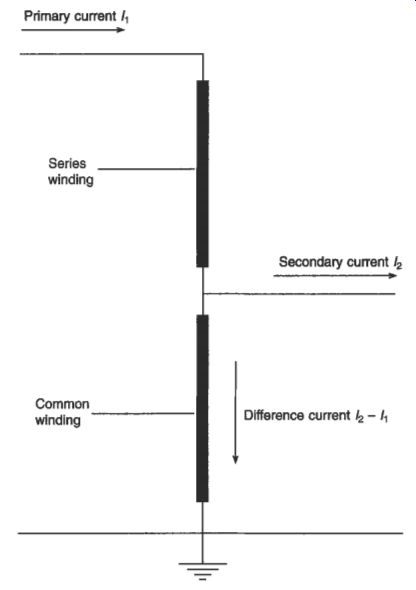
Fig. 12 Autotransformer connection
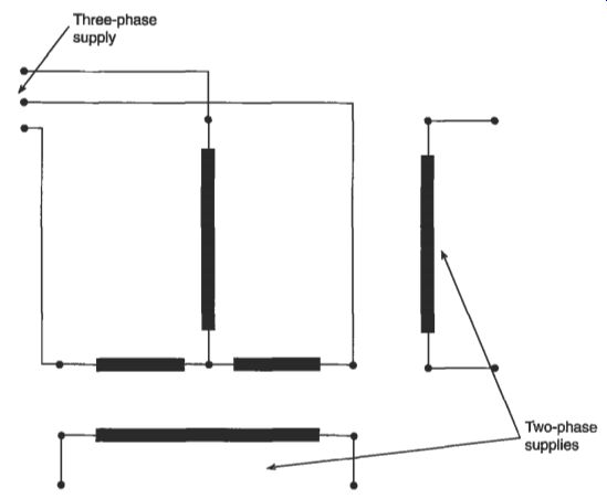
Fig. 13 Scott connection of transformers
In many transmission transformers, an autotransformer connection is employed.
The connection is shown in Fig. 12, and unlike the two-winding transformer in which primary and secondary are isolated, it involves a direct connection between two electrical systems. This connection can have a cost advantage where the ratio of input and output voltages is less than 5 : 1. Current flowing in the 'series' winding corresponds to that in the higher-voltage system only. The 'common' winding carries a current which is the difference between the two systems, and being sized for this lower current it can be significantly cheaper. The autotransformer is more susceptible to damage from lightning impulse voltages and it has a lower strength against through- fault currents; both of these weaknesses can be corrected, but at increased cost.
It may occasionally be necessary to make a three-phase to two-phase transformation.
This might be in order to supply an existing two-phase system from a new three-phase system, or to supply a two-phase load (such as a furnace) from a three-phase system, or to supply a three-phase load (such as a motor) from a two-phase system.
In all these cases the usual method of making the transformation is by using two single-phase transformers connected to each of the systems and to each other by the Scott connection.
A Scott connection is shown in Fig. 13. On one transformer the turns ratio is equal to the transformation ratio, and the mid-point of the winding connected to the three-phase system is brought out for connection to the other single-phase transformer.
The second transformer has a turns ratio of 0.866 times the transformation ratio. The primary winding is connected between the third phase of the three-phase supply and the mid-point of the primary winding of the first transformer. The secondary windings of the two transformers are connected to the two-phase supply (or load) using a three- or four-wire connection.
2.4 Bushings
Where transformers are enclosed within tanks to contain the insulating and cooling fluid, it is necessary to link the windings connections to the network using through- bushings which penetrate the tank.
Low-voltage bushings are generally solid. They are made of porcelain, ceramic or epoxy insulation with sufficient electrical strength to withstand abnormal voltages due to lightning activity or switching operations, and to withstand the service voltage over the lifetime of the transformer. Some low-voltage bushings carry high current and cooling is necessary. In such cases it is usual to employ a hollow porcelain construction in which the internal connections are cooled by the oil in the tank.
High-voltage bushings must withstand much higher voltage transients. They are usually of composite construction with a core of oil-impregnated or resin-bonded paper in an outer porcelain or epoxy cylinder. This outer cylinder is 'shedded' at the outside (air) end to increase its electrical strength under wet conditions. A typical high-voltage bushing with an oil-paper core is shown in Fig. 14(a); its internal construction detail is shown in Fig. 14(b).
2.5 Tapchangers
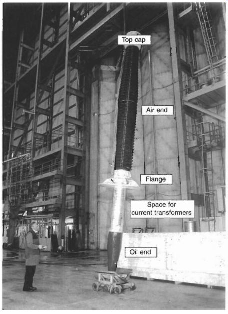
Fig. 14(a) High-voltage oil-air bushing
---------
Line connection TOP cap capacitance foils Oil end ceramic Stress distributor Connection to winding
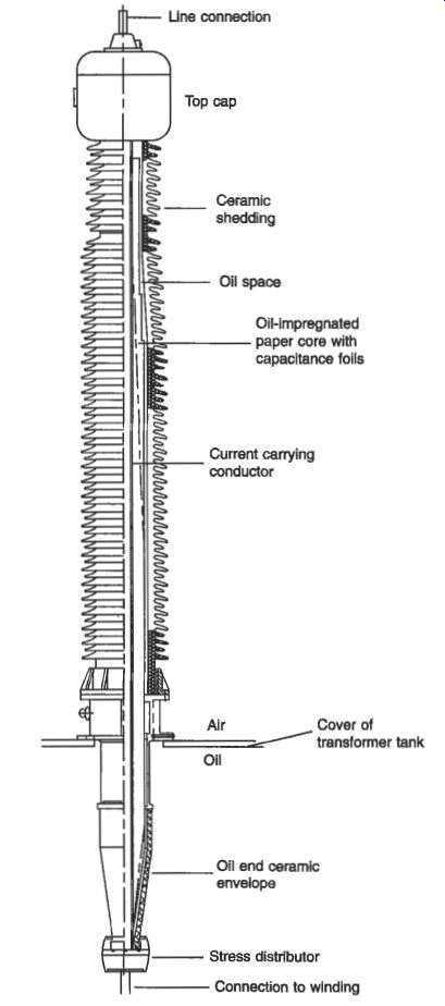
Fig. 14(b) Internal construction of high-voltage oil-air bushing ' tank
----------
It has been explained in section 6.1 that when a transformer carries load current there is a variation in output voltage from a transformer which is known as regulation. In order to compensate for this, additional turns are often made available so that the voltage ratio can be changed using a switch mechanism known as a tapchanger. An off-circuit tapchanger can only be adjusted to switch additional turns in or out of circuit when the transformer is de-energized; it usually has between two and five tapping positions. An on-load tapchanger (OLTC) is designed to increase or decrease the voltage ratio when the load current is flowing, and the OLTC should switch the transformer load current from the tapping in operation to the neighboring tapping without interruption. The voltage between tapping positions (the step voltage) is normally between 0.8 per cent and 2.5 per cent of the rated voltage of the transformer.
OLTC mechanisms are based either on a slow-motion reactor principle or a high- speed resistor principle. The former is commonly used in North America on the low- voltage winding, and the latter is normally used in Europe on the high-voltage winding.
The usual design of OLTC in Europe employs a selector mechanism to make connection to the winding tapping contacts and a diverter mechanism to control current flows while the tapchanging takes place. The selector and diverter mechanisms may be combined or separate, depending upon the power rating. In an OLTC which comprises a diverter switch and a tap selector, the tap change occurs in two operations.
First, the next tap is selected by the tap switch but does not carry load current, then the diverter switches the load current from the tap in operation to the selected tap.
The two operations are shown in seven stages in Fig. 15.
High-voltage winding
Switching sequence of diverter switch
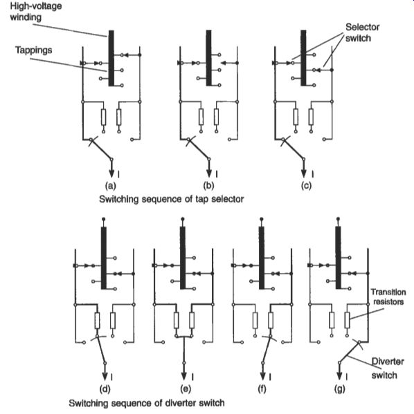
Fig. 15 Operation of selector and diverter switches in an on-load tap
changer of high-speed resistor type.
The tap selector operates by gearing directly from a motor drive, and at the same time a spring accumulator is tensioned. This spring operates the diverter switch in a very short time (40-60 ms in modern designs), independently of the motion of the motor drive. The gearing ensures that the diverter switch operation always occurs after the tap selection has been completed. During the diverter switch operation shown in Fig. 15(d), (e) and (f), transition resistors are inserted; these are loaded for 20-30 m and since they have only a short-time loading the amount of material required is very low.
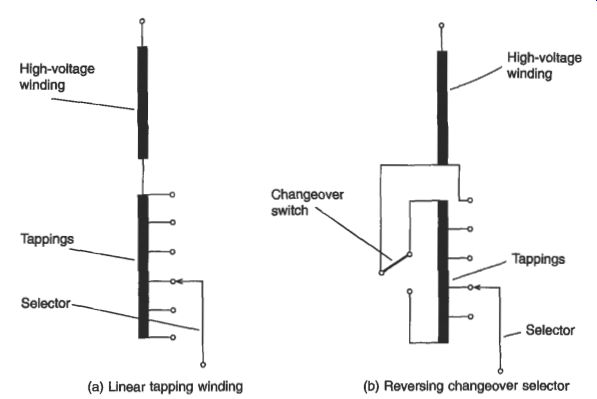
Fig. 16 Basic arrangements of tapping windings --- (a) Linear tapping
winding (b) Reversing changeover selector -- (c) Coarse-fine tapping windings
The basic arrangement of tapping windings is shown in Fig. 16. The linear arrangement in Fig. 16(a) is generally used on power transformers with moderate regulating ranges up to 20 per cent. The reversing changeover selector shown in
Fig. 16(b) enables the voltage of the tapped winding to be added or subtracted from the main winding so that the tapping range may be doubled or the number of taps reduced. The greatest copper losses occur at the position with the minimum number of effective turns. This reversing operation is achieved with a changeover selector which is part of the tap selector of the OLTC. A two-part coarse-fine arrangement shown in Fig. 16(c) may also be used. In this case the reversing changeover selector for the fine winding can be connected to the 'plus' or 'minus' tapping of the coarse winding, and the copper losses are lowest at the position of the lowest number of effective turns. The coarse changeover switch is part of the OLTC. Regulation is mostly carried out at the neutral point in star windings, resulting in a simple, low-cost, compact OLTC and tapping windings with low insulation strength to earth. Regulation of delta windings requires a three-phase OLTC, in which the three phases are insulated for the highest system voltage which appears between them; alternatively three single-phase OLTCs may be used.
2.6 Cooling equipment
Transformers may be naturally cooled, in which case the cooling medium (oil or air) circulates by thermosyphon forces, or they may be forced cooled, with fans or pumps to circulate the air or oil over the core and through the windings.
In oil-cooled transformers a more economic solution is to use directed oil-flow cooling in which oil is pumped directly into the windings. The oil is cooled by passing (or pumping) it through plate radiators, which may be externally cooled by fans, or by using forced air-cooled tubular construction, or by pumping it through water coolers. Designations for these cooling systems which identify both the cooling fluid and the type of cooling have been assigned by IEC and these are summarized in Table 1.
3. Main classes of transformer
Transformers are used for a wide variety of purposes, with the complete range of voltage and power ratings as well as many special features for particular applications.
The following covers the main types.
3.1 Transformers for electronics
Transformers for electronic circuits or for low-voltage power supplies are used to match the supply voltage to the operating voltage of components or accessories, or to match the impedance of a load to a supply in order to maximize power throughput.
The core is usually constructed in the low-power transformers from C- and I-laminations or from E- and I-laminations. The windings are usually of round enameled wire, and the assembly may be varnished or encapsulated in resin for mechanical consolidation and to prevent ingress of moisture.
Increasing numbers of this type operate at high frequencies in the kHz range and use laminations of special steel often containing cobalt to reduce the iron losses.
------------

Table 1 Cooling system designations
For oil immersed transformers a four-letter code is used: First letter: internal cooling medium in contact with windings:
0 K L mineral oil or insulating liquid with fire point S3OO0C insulating liquid with fire point >300% insulating liquid with no measurable fire point Second letter: circulation mechanism for internal cooling medium: N natural thermosyphon flow F D forced oil circulation, but thermosyphon cooling in windings forced oil circulation, with oil directed into the windings Third letter: external cooling medium A air W water Fourth letter: circulation mechanism for external cooling medium N natural convection F forced circulation Examples: ONAN or OFAF For dry-type transformers a four-letter code is used: First letter: internal cooling medium in contact with the windings A air G gas Second letter: circulation mechanism for internal cooling medium N natural convection F forced cooling Third letter: external cooling medium A air G gas Fourth letter: circulation mechanism for external cooling medium N natural convection F forced cooling Examples: AN or GNAN
--------------
3.2 Small transformers
These are used for stationary, portable or hand-held power supply units, as isolating transformers and for special applications such as burner ignition, shavers, shower heaters, bells and toys. They may be used to supply three-phase power up to 40 kVA at frequencies up to 1 MHz. These transformers are usually air insulated, the smaller units using enameled windings wires and ring cores and the larger units using C- and I- or E- and I-laminated cores.
Safety is a major concern for these transformers and they are identified as class I, class I1 or class III. Class I units are insulated and protected by an earth terminal. Class II transformers have double insulation or reinforced insulation. Class I11 trans- formers have outputs at Safety Extra-Low Voltages (SELV) below 50 V ac or 120 V dc.
3.3 Distribution transformers
These are used to distribute power to domestic or industrial premises. They may be single phase or three phase, pole mounted or ground mounted, and they have ratings ranging from 16 kVA up to 2500 kVA. The windings and core are immersed in mineral oil, with natural cooling, and there are two windings per phase. The primary (high-voltage) winding has a highest voltage ranging from 3.6 kV to 36 kV; the secondary (low-voltage) winding voltage does not exceed 1.1 kV. The high-voltage winding is usually provided with off- circuit tappings of * 2.5 percent, or +2 x 2.5 per cent, -3 x 2.5 percent.
The preferred values of rated output are 16,25,50, 100, 160,250,400,630, 1000, 1600 and 2500 kVA, and the preferred values of short-circuit impedance are 4 per cent or 6 per cent. Losses are assigned from lists, for instance from BS 7821-1, or by using a loss-capitalization formula.
The core and windings of a typical distribution transformer rated at 800 kVA, 11 0o0/440 V are shown in Fig. 17.
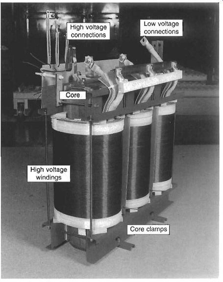
Fig. 17 Core and windings of an 800 kVA, 11 000/440 V distribution transformer
3.4 Supply transformers
These are used to supply larger industrial premises or distribution substations. Ratings range from 4 MVA to 30 MVA, with primary windings rated up to 66 kV and secondary windings up to 36 kV. Transformers in this class are fluid cooled. Most supply transformers use mineral oil, but for applications in residential buildings, oil rigs and some factories the coolant may be synthetic esters, silicone fluid or some other fluid with a higher fire point than mineral oil.
3.5 Transmission (or intertie) transformers
These are among the largest and highest voltage transformers in use. They are used to transmit power between high-voltage networks. Ratings range from 60 MVA to 1000 MVA and the windings are rated for the networks which they link, such as 33, 66, 132, 275 and 400 kV in the UK, or voltages up to 500 kV or 800 kV in other countries. The impedance of a transmission transformer is usually 18 per cent in the UK, or 8 per cent in continental Europe, but for some system conditions, an impedance of up to 30 percent is used.
Transmission transformers are oil filled, and are usually fitted with oil pumps and radiator fans to assist cooling of the windings and cores. They are usually fitted with OLTCs, but some networks at 400 kV and 275 kV are linked by transformers without regulating windings. The core and windings of a five-legged transmission transformer rated at 1000 MVA and 400 kVl275 kV111 kV are shown in Fig. 18.
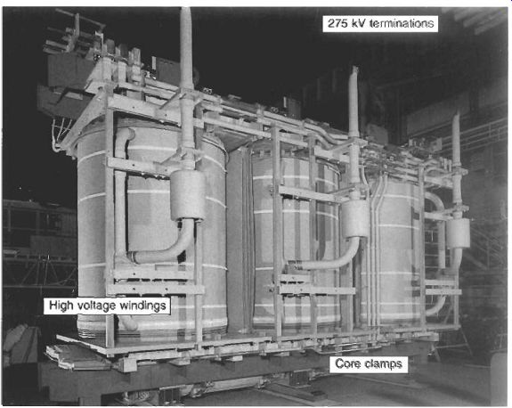
Fig. 18 Core and windings of a 1000 MVA, 400/275 kV transmission transformer
3.6 Generator (or step-up) transformers
Power is usually generated in large power stations at typically 18-20 kV, and generator transformers are used to step up this voltage to the system voltage level. These transformers are usually rated at 400, 500, 630, 800 or 1000 MVA. Base-load power stations usually operate continuously at full load, and the power is transformed to the highest operating voltage in one step. Combined-cycle gas turbine stations may be embedded in the transmission and distribution system at lower operating voltages such as 132 kV. Generator transformers are usually fitted with regulating windings and OLTCs.
3.7 Phase-shifting transformers
Where power is transmitted along two or more parallel transmission lines, the power flow divides between the lines in inverse proportion to the line impedances. Higher power is therefore transmitted through the line with lowest impedance and this can result in overload on that line, when the parallel line is only partly loaded. Phase- shifting transformers are used to link two parallel lines and to control power flow by injecting a voltage 90" out of phase (in quadrature) with the system voltage into one line, at either leading or lagging power factor. Where the transformer controls the phase angle but not the voltage, the unit is known as a quadrature booster. Where the voltage is also controlled, the unit is known as a phase-shifting transformer: Fig. 19 shows a 2000 MVA, 400 kV quadrature booster transformer on site; the unit is split between two tanks in order to meet construction limitations of size and weight.
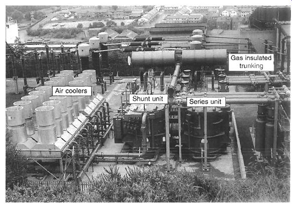
Fig. 19 -- 2000 MVA 400 kV quadrature booster transformer in two tanks
on site
3.8 Converter transformers
Fig. 20 Schematic diagram of ac/dc transmission system
Where power is transmitted through an HVDC system, a converter station is used to change ac power to dc using multiple rectifier bridges. DC power is converted back to ac using inverter bridges. Converter transformers handle ac power and power at mixed ac/dc voltages by combining the power flow through 12 phases of rectifier/ inverter bridges through dc valve windings.
The insulation structure must withstand all normal and abnormal conditions when ac voltage is mixed with dc voltage of differing polarities over the operating temperature range. The presence of dc currents may also cause dc saturation of the core, leading to abnormal magnetizing currents and variations in sound.
A phase of a three-phase converter transformer bank typically comprises a high- voltage primary winding and two secondary ac/dc valve windings. Three such transformers together form the two secondary three-phase systems; one is connected in delta and the other in star. Each secondary system feeds a six-pulse bridge and the two bridges are connected in series to form a 12-pulse arrangement, as shown schematically in Fig. 20. Two such transformer banks are used with the secondary circuits connected in opposite polarity to form a +/-215 kV dc transmission system.
3.9 Railway transformers
Transformers for railway applications may be trackside units to supply power to the track, or on-board transformers in the locomotive or under the coaches, to power the drive motors.
Trackside transformers are subjected to uneven loading depending upon the position of the train in the railway system. On-board transformers are designed for the lowest possible weight, resulting in a high-loss performance. Modem train control systems using thyristors or GTOs subject the transformers to severe harmonic currents that require special design consideration.
3.10 Rectifier and furnace transformers
Special consideration is needed for transformers in industrial applications involving arc furnaces or heavy-current dc loads in electrochemical plant. The primary windings in such cases are usually rated at 33 kV or 132 kV in the UK, but the secondary windings carry many thousands of amperes and ace rated at less than 1 kV. Current sharing between parallel paths in the transformer becomes important because of the magnetic fields created by the high currents. These strong magnetic fields can cause excess heating in magnetic steels if these are used in the structure of the transformer, because of the flow of proximity currents in the steel. To reduce this excess heating, non-magnetic steel is often used to form part of the tank or the cover.
The OLTCs in furnace transformers are subject to a heavy duty; they may perform hundreds of thousands of operating cycles a year, which is more than a lifetime's duty for many transmission transformers.
3.11 Dry-type transformers
A dry-type construction is possible where a higher-temperature class of insulation is required than is offered by cellulose and a class '0' or class 'K fluid. Dry-type transformers use non-cellulosic solid insulation and the windings may be varnish dipped to provide a class 'C' capability, or vacuum encapsulated in epoxy resin to form a class T' or class 'H' system. Ratings can be up to 20 MVA at voltages up to 36 kV. Overload performance can be provided by fans.
This type of transformer is more expensive than a fluid-filled equivalent, and because of the reduced fire risk they are used in special applications where the public are involved, such as underground tunnels, residential blocks of flats or oil rigs.
A typical cast-resin transformer rated 2500 kVA, 11 000/440 V is shown in Fig. 21.
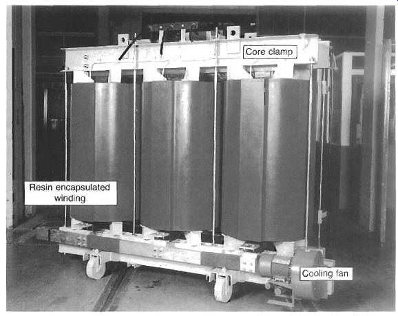
Fig. 21 Dry-type 2500 kVA, 11,000/440 V transformer with cast-resin
encapsulation
3.1 2 Gas-filled transformers
For applications where low flammability is paramount, designs have been developed in which the transformer is insulated and cooled with SF6 gas. This provides an alternative to dry-type construction, but it has only been used on a limited scale.
High-voltage SF6 transformers are available at high cost, but this may be justifiable in cases of high land values, where the overall 'footprint' of the unit can be reduced by the elimination of fire-fighting equipment.
4. Rating principles
4.1 Rated power
The rated power of each winding in a transformer refers to a continuous loading and it is a reference value for guarantees and tests concerning load losses and temperature rise. Where a transformer winding has different values of apparent power under different cooling conditions, the highest value is defined as the rated power. A two-winding transformer is given only one value of rated power, which is identical for both windings, but a multi-winding transformer may have reduced levels of rated power on auxiliary windings.
When a transformer has rated voltage applied to the primary winding and rated current flows through the secondary winding, the transformer is carrying rated power for that set of windings. This definition of rated power, used by IEC, implies that the rated power is the value of power input to the transformer, including its own absorption of active and reactive power. The secondary voltage under full load differs from the rated voltage by the voltage drop in the transformer.
In North America a different definition is adopted in ANSUIEEE standard C57.1200. Here, rated power is based on the output that can be delivered at rated secondary voltage, and allowance must be made so that the necessary primary voltage can be applied to the transformer. The difference between basing rated power on loaded voltages (IEC) or open-circuit voltages (ANSUIEEE) is significant.
4.2 Overloading
Although transformers are rated for continuous operation, it is possible to supply overloads for limited periods. The analysis of overloading profiles is based on the deterioration of cellulose. At temperatures above the rated temperature, cellulose degrades at a faster rate, and the load cycle should therefore include a period of operation at lower temperature to balance effects of these faster ageing rates at higher temperature. In general, the ageing rate doubles for every 8°C rise in temperature.
When the ambient temperature is below the rated ambient temperature it is also permissible to overload the transformer, the limit of the overloading being the operating temperature of the winding. Under severe operational pressures it is sometimes necessary to overload a transformer well beyond its nameplate rating, but such an operation will usually result in shorter life. IEC 354 provides a guide to overloading of oil-filled transformers based on these principles.
A maximum winding temperature of 140°C should not be exceeded even under emergency conditions, because free gas can be produced by cellulose at temperatures above this, and gas bubbles may cause dielectric failure of the windings.
4.3 Parallel operation of transformers
For operational reasons it may be necessary to operate transformers connected directly in parallel. For successful parallel operation, the transformers must have:
- the same voltage ratings and ratio (with some tolerance)
- the same phase-angle relationship (clock-hour number)
- the same percentage impedance (with some tolerance)
It is not advisable to parallel operate transformers with widely different power ratings as the natural impedance for optimal design varies with the rating of the transformer.
The power divides between parallel-connected transformers in a relationship which is inversely proportional to their impedances; a low-impedance transformer operated in parallel with a higher-impedance unit will pass the greater part of the power and may be overloaded. A mismatch in loading of up to 10 per cent is normally acceptable.
5. Test methods
5.1 Specification testing
Transformers for power supply units and isolating transformers are subject to production testing, where compliance is generally checked by inspection and electrical tests.
The electrical tests establish earthing continuity (for class I), no-load output voltage, dielectric strength between live parts of the input circuit and accessible conducting parts of the transformer, and dielectric strength between input and output circuits.
Tests on larger transformers are carried out as part of the manufacturing process to ensure that transformers meet the characteristics specified by the purchaser. The tests prescribed by IEC are grouped in three categories, these being routine tests, type tests and special tests:
- routine tests, to be carried out on all transformers
- type rests, to be carried out on new designs or the first unit of a contract
- special tests, to be carried out at the specific request of the purchaser
(a) Routine rests
These are carried out on all transformers and include:
--measurement of winding resistance using a dc measurement circuit or a bridge measurement of voltage ratio and check of phase displacement. The voltage ratio is checked on each tap position and the connection symbol of three-phase transformers is confirmed.
--measurement of short-circuit impedance and load loss. The short-circuit impedance (including reactance and ac resistance in series) is determined by measuring the primary voltage necessary to circulate full-load current with the secondary terminals short-circuited. The load loss (copper loss) is measured using the same circuit.
--measurement of no-load loss and magnetizing current, at rated voltage and frequency. This is measured on one set of windings with the other windings open-circuit. Because the power factor at no-load may be between 0.1 and 0.2, special low power factor wattmeters are necessary to ensure accuracy. A three- wattmeter connection is used for load loss measurement of three-phase transformers, because the previously used two-wattmeter method is inaccurate.
--di-electric tests, consisting of applied voltage and induced voltage tests, sometimes linked with a switching surge test. The applied voltage test verifies the integrity of the winding insulation to earth and between windings, and the induced voltage test verifies the insulation between turns and between windings. The general requirements set down by EC are shown in Table 2. For transformers rated up to 300 kV, the induced voltage test is for one minute at an overvoltage of between 2.5 and 3.5 times rated voltage, carried out at a higher frequency to avoid core saturation. For rated voltages over 300 kV, the induced test is for 30 minutes at 1.3 or 1.5 times rated voltage, with an initial short period at a higher voltage to initiate activity in any vulnerable partial discharge sites; this is linked with a partial discharge test. This long-term test will not prove the insulation against switching overvoltages, and so for this it must be linked to a switching impulse test.
--tests on OLTCs to confirm the timing of the tapchanger mechanism and to prove the capability on full-voltage and full-current operation.
(b) Type tests
These are carried out on new designs, or on the first unit of a contract. They include:
a temperature rise test using the normal cooling equipment to verify the temperature rise of the windings under full-load or overload conditions. For smaller transformers it may be possible to carry out the temperature rise test at full voltage by supplying a suitable load. For larger transformers it is more usual to supply the total losses (load loss and no-load loss) under short-circuit conditions and to establish the top oil temperature and the average winding temperature at a lower voltage. Where a number of transformers are available, it is possible to supply them in a 'back-to-back' connection and to make the test at full voltage and full current. The test is carried out over a period of 8 to 24 hours to establish steady-state temperatures, and it may be associated with Dissolved Gas Analysis (DGA) of oil samples taken during the test to identify possible evidence of micro-deterioration in the insulation at high local temperatures.
Table 6.2 Dielectric test values for transformers Rated withstand voltages for windings of transformers e300 kV Rated withstand voltages for windings of transformers 2300 kV, in conjunction with a 30 m test at 1.3~ or 1.5~ rated voltage
Notes: 1 In general the switching impulse test level is J 83% of the lightning impulse test level. 2. These test levels are not applicable in North America.
--a lightning impulse voltage test to prove performance under atmospheric lightning conditions. The specified impulse waveform has a 1 ps front time (time-to- crest) and a 50 ps tail time (time from crest to half-crest value). The winding is tested at a level prescribed by IEC which is linked to the rated voltage. This is set out in Table 6.2. One test application is made at 75 percent of the test value (Reduced Full Wave, or RFW) and this is followed by three test applications at full test value (FW). The test is considered satisfactory if there are no discrepancies between the recorded oscillograms of applied voltage and between the recorded oscillograms of neutral current.
(c) Special tests
These are carried out at the specific request of the purchaser. The more usual special tests are:
--chopped-impulse wave test. The purchaser may wish to simulate the situation when a lightning surge propagated along a transmission line is chopped to earth by a lightning protection rod gap mounted on the bushing. The Chop Wave (CW) is specified as an FW waveform with a chop to earth occurring between 3 and 7 seconds after the crest. The chop-wave test is combined with the lightning impulse voltage test and the test sequence is 1-RFW. 1-FW, 2- CW and 2-FW test applications, sometimes followed by a further RFW for 0
0 e comparison purposes. A successful test shows no discrepancies between applied voltage oscillograms or between neutral current oscillograms, although if rod gaps are used to perform the chopped-wave test there may be acceptable deviations between neutral current oscillograms after the time of chop. If a triggered gap is used to control time of chop the oscillograms should be identical.
--determination of zero-sequence impedance, measured between the line terminals of a star-connected or zigzag-connected winding connected together, and its neutral terminal. The impedance is expressed in ohms per phase, and it is a measure of the impedance presented by the transformer to a three-phase fault to earth.
short-circuit withstand test to verify the integrity of the transformer under through-fault conditions. IEC recommendations allow the withstand performance of a winding to be demonstrated by calculation or by test. The resource needed to test fully a large power transformer is substantial, and few test facilities are available in the world.
--determination of sound levels. The sound produced by a transformer is predominantly due to magnetostriction in the core and is related to core flux density. The sound level can be measured in terms of sound power, sound pressure or sound intensity. The last method was developed especially for measurement of low sound levels in the presence of high sound ambients. In transformers which have been designed with low flux density to reduce the magnetostriction effect, the predominant sound may be produced by the windings as a result of movements caused by the load currents. This load-current generated sound should be measured by the sound intensity method.
5.2 In-service testing
Two types of in-service testing are used. Surveillance testing involves periodic checks, and condition monitoring offers a continuous check.
(a) Surveillance testing--oil samples
When transformers are in operation many users carry out surveillance testing to monitor operation. The most simple tests are carried out on oil samples taken on a regular basis. Measurement of oil properties such as breakdown voltage, water content, acidity, dielectric loss angle, volume resistivity and particle content all give valuable information on the state of the transformer. DGA gives early warning of deterioration due to electrical or thermal causes, particularly sparking, arcing and service overheating.
Analysis of the oil by High-Performance Liquid Chromatography (HPLC) may detect the presence of furanes or furfuranes which will provide further information on moderate overheating of the insulation.
(b) Condition monitoring
Sensors can be built into the transformer so that parameters can be monitored on a continuous basis. The parameters which are typically monitored are winding temperature, tank temperature, water content, dissolved hydrogen, load current and voltage transients. The data collection system may simply gather and analyze the information, or it may be arranged to operate alarms or actuate disconnections under specified conditions and limits which represent an emergency.
6. Commissioning, maintenance and repair
6.1 Commissioning
Power transformers can be transported to site complete with oil, bushings, tapchangers and cooling equipment. It is then a relatively simple matter to lift them onto a pole or plinth and connect them into the system.
Large transformers are subject to weight restrictions and size limitations when they are moved by road or rail and it is necessary to remove the oil, bushings, cooling equipment and other accessories to meet these limitations. Very large transformers are usually carried on custom-built transporters, such as the 112-wheel transporter shown in Fig. 22; this is carrying a 1000 MVA, 400 kV transmission transformer that has been dismantled to meet a 400 tonne road weight restriction. Once a transformer of this size arrives on site, it must be lifted or jacked onto its plinth for re-erection.
In some cases with restricted space it may be necessary to use special techniques such as water skates to maneuver the transformer into position.
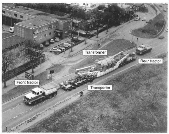
Fig. 22 Road transporter carrying a 1000 MVA, 400 kV transmission transformer
When the transformer has been erected and the oil filled and reprocessed, it is necessary to carry out commissioning tests to check that all electrical connections have been correctly made and that no deterioration has occurred in the insulation system. These commissioning tests are selected from the routine tests and usually include winding resistance and ratio, magnetizing current at 440 V, and analysis of oil samples to establish breakdown strength, water content and total gas content.
6.2 Maintenance
Transformers require little maintenance in service, apart from regular inspection and servicing of the OLTC mechanism. The diverter contacts experience significant wear due to arcing, and they must be replaced at regular intervals which are determined by the operating regime. For furnace transformers it may be advisable to filter the oil regularly in a diverter compartment in order to remove carbon particles and maintain the electrical strength.
The usual method of protecting the oil breather system in small transformers is to use silicone gel breathers to dry incoming air; in larger transformers refrigerated breathers continuously dry the air in a conservator. Regular maintenance (at least once a month) is necessary to maintain a silica gel breather in efficient working order.
If oil samples indicate a high water content then it may be necessary to dry the oil using a heating-vacuum process. This also indicates a high water content in the paper insulation and it may be necessary to re-dry the windings by applying a heating and vacuum cycle on site, or to return the transformer to the manufacturer for reprocessing or refurbishment.
6.3 Diagnostics and repair
In the event of a failure, the user must first decide whether to repair or replace the transformer. Where small transformers are involved, it is usually more economic to replace the unit. In order to reach a decision, it is usually necessary to carry out diagnostic tests to identify the number of faults and their location. Diagnostic tests may include the surveillance tests referred to in section 5.2, and it may also be decided to use acoustic location devices to identify a sparking site, low-voltage impulse tests to identify a winding fault and frequency response analysis of a winding to an applied square wave to detect winding conductor displacement.
If the fault is in a winding, it usually requires either replacement of the winding in a repair workshop or rewinding by the manufacturer, but many faults external to the windings such as connection or core faults can be corrected on site.
Where a repair can be undertaken on site it is essential to maintain dry conditions in the transformer by continual purging using dry air. Any material taken into the tank must be fully processed and a careful log should be maintained of all materials taken into and brought out of the tank.
When a repair is completed, the transformer must be re-dried and re-impregnated, and the necessary tests carried out to verify that the transformer can be returned to service in good condition.
7. Standards
The performance requirements of power transformers are covered by a range of international, regional and national standards. At the highest level are the recommendations published by the International Electrotechnical Commission (IEC). These are performance standards, but they are not mandatory unless referred to in a contract.
Regional standards in Europe are Euro-Norms (ENS) or Harmonized Documents (HDs) published by the European Committee for Electrotechnical Standardization (CENELEC). CENELEC standards are part of European law, ENS must be transposed into national standards and no national standard may conflict with an HD. Many ENS and HDs are based on EC recommendations, but some have been specifically prepared to match European legislation requirements such as EU Directives.
National standards in the UK are published by the British Standards Institution (BSI). BSI standards are generally identical to IEC or CENELEC standards, but some BS standards address issues not covered by IEC or CENELEC. In North America the main regional standards are published by the American National Standards Institute (ANSI) in conjunction with the Institute of Electrical and Electronic Engineers (IEEE). ANSYIEEE standards are generally different from EC recommendations, but the two are becoming closer as a result of international harmonization following GATT treaties on international trade.
The main transformer standards in IEC, CENELEC and BSI are shown in Table 6.3, together with their interrelationship. Where appropriate the equivalent ANSI/ IEEE standard is also referenced.

Table 3 Comparison of inter-relation. regional and national standards
for transformers.