AMAZON multi-meters discounts AMAZON oscilloscope discounts
1. Nomenclature and units
This guide uses notation in accordance with the current British and International Standards. Units for engineering quantities are printed in upright roman characters, with a space between the numerical value and the unit, but no space between the decimal prefix and the unit, e.g. 275 kV. Compound units have a space, dot or / between the unit elements as appropriate, e.g. 1.5 N m, 300 m/s, or 9.81 m s^-2.
Variable symbols are printed in italic typeface, e.g. V. For ac quantities, the instantaneous value is printed in lower case italic, peak value in lower case italic with caret (^), and rms value in upper case, e.g. i, i, I. Symbols for the important electrical quantities with their units are given in Table 1, and decimal prefix symbols are shown in Table 2. Graphical symbols for basic electrical engineering components are shown on Fig. 1.

Table 1 Symbols for standard quantities and units

Table 2 Standard decimal prefix symbols
2. Electromagnetic fields
2.1 Electric fields
Any object can take an electric or electrostatic charge. When the object is charged positively, it has a deficit of electrons, and when charged negatively it has an excess of electrons. The electron has the smallest known charge, -1.602 x 10^-19 C.
Charged objects produce an electric field. The electric field strength E (V/m) at a distance d(m) from an isolated point charge Q(C) in air or a vacuum is given by E=- Q 4m0d2 where the permittivity of free space Eo = 8.854 x 10^-12 F/m. If the charge is inside an insulating material with relative permittivity q the electric field strength becomes
(eqn. 2)
Any charged object or particle experiences a force when inside an electric field. The force F (N) experienced by a charge Q (C) in an electric field strength E (V/m) is given by
F=QE (eqn. 3)
Electric field strength is a vector quantity. The direction of the force on one charge due to the electric field of another is repulsive or attractive. Charges with the same polarity repel; charges with opposite polarities attract.
Work must be done to move charges of the same polarity together. The effort required is described by a voltage or electrostatic potential. The voltage at a point is defined as the work required to move a unit charge from infinity or from earth. (It is normally assumed that the earth is at zero potential.) Positively charged objects have a positive potential relative to the earth.
If a positively charged object is held some distance above the ground, then the voltage at points between the earth and the object rises with distance from the ground, so that there is a potential gradient between the earth and the charged object.
There is also an electric field pointing away from the object, towards the ground. The electric field strength is equal to the potential gradient, and opposite in direction.
E=-- dV/dx (eqn. 4)
2.2 Electric currents
Electric charges are static if they are separated by an insulator. If charges are separated by a conductor, they can move giving an electric current. A current of one ampere flows if one coulomb passes along the conductor every second.
I=- Q t
A given current flowing through a thin wire represents a greater density of current than if it flowed through a thicker wire. The current density J (Nm^2) in a wire with cross-section area A (m^2) carrying a current I (A) is given by
J=- I A (eqn. 6)
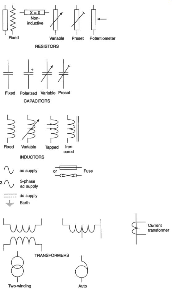
Fig. 1 Standard graphical symbols
For wires made from most conducting materials, the current flowing through the wire is directly related to the difference in potential between the ends of the wire.
Ohm's law gives this relationship between the potential difference V(V) and the current I (A) as V=IR or I=VG (eqn. 7)
where R (a) is the resistance, and G (S) = 1/R is the conductance (Fig. 2). For a wire of length l and cross-section area A, these quantities depend on the resistivity p (a - m) and conductivity Q (Wm) of the material
R I 4 V= IR
(eqn. 8)
1 A R=p- and G=o- A I

Fig. 2 Ohm's law
For materials normally described as conductors p is small, while for insulators p is large. Semicondz6ctors have resistivity in between these extremes, and are usually very dependent on purity and temperature.
In metal conductors, the resistivity increases with temperature approximately linearly:
RT=RT,(l +a("- To)) (eqn. 9)
…for a conductor with resistance RT, at reference temperature To. This is explained in more detail in section 3.4.1.
Charges can be stored on conducting objects if the charge is prevented from moving by an insulator. The potential of the charged conductor depends on the capacitance C (F) of the metal/insulator object, which is a function of its geometry.
The charge is related to the potential by A simple parallel-plate capacitor, with plate area A, insulator thickness d and relative permittivity E, has capacitance
Q=CV (eqn. 10)
(eqn. 11)
2.3 Magnetic fields
A flow of current through a wire produces a magnetic field in a circular path around the wire. For a current flowing forwards, the magnetic field follows a clockwise path, as given by the right-hand corkscrew rule (Fig. 3). The magnetic field strength H (A m-I) is a vector quantity whose magnitude at a distance d from a current Z is given by:
(eqn. 12)
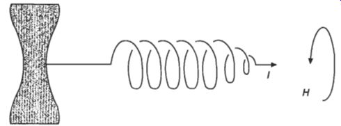
Fig. 3 Right-hand corkscrew rule
For a more complicated geometry, Amptrek law relates the number of turns N in a coil, each carrying a current I, to the magnetic field strength H and the distance around the lines of magnetic field I. HI (eqn. 13)
where F, (ampere-turns) is the magnetomotive force (mmf). This only works for situations where H is uniform along the lines of magnetic field.
The magnetic field produced by a current does not depend on the material surrounding the wire. However, the magnetic force on other conductors is greatly affected by the presence of ferromagnetic materials, such as iron or steel. The magnetic field produces a magnetic flux density B (T) in air or vacuum
B=M (eqn. 14)
where the permeability office space po = 4n x lo-' Wm.
In a ferromagnetic material with relative permeability
B = p&H (eqn. 15)
A second conductor of length I carrying an electric current Z will experience a force F in a magnetic flux density B F = BZ1 (eqn. 16)
The force is at right angles to both the wire and the magnetic field. Its direction is given by Fleming's left-hand rule (Fig. 4). If the magnetic field is not itself perpendicular to the wire, then the force is reduced; only the component of B at right angles to the wire should be used.
A flow of magnetic flux @ (Wb) is caused by the flux density in a given cross- section area A as
@= BA (eqn. 17)
The mmf F, required to cause a magnetic flux @to flow through a region of length I and cross-section area A is given by the reluctance R, (ANb) or the permeance A (Wb/A) of the region
where (eqn. 18)
1 R,= - POP4 (eqn. 19)
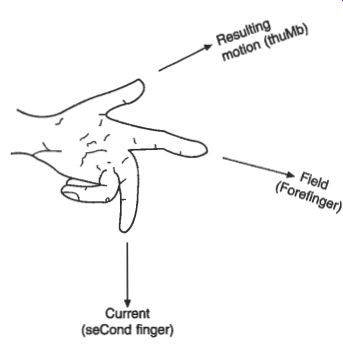
Fig. 4 Fleming's left-hand rule
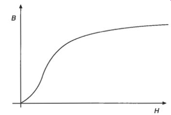
Fig. 5 Magnetic characteristics
In ideal materials, the flux density B is directly proportional to the magnetic field strength H. In ferromagnetic materials the relation between B and H is non-linear (Fig. 5(a)), and also depends on the previous magnetic history of the sample. The magnetization or hysteresis or BH loop of the material is followed as the applied magnetic field is changed (Fig. 5(b)). Energy is dissipated as heat in the material as the operating point is forced around the loop, giving hysteresis loss in the material.
These concepts are developed further in section 3.2.
2.4 Electromagnetism
Any change in the magnetic field near a wire generates a voltage in the wire by electromagnetic induction. The changing field can be caused by moving the wire in the magnetic field. For a length 1 of wire moving sideways at speed v (ds) across a magnetic flux density B, the induced voltage or electromotive force (emf) is given by The direction of the induced voltage is given by Fleming's right-hand rule (Fig. 6). An emf can also be produced by keeping the wire stationary and changing the magnetic field. In either case the induced voltage can be found using Faraday's law.
If a magnetic flux 0 passes through a coil of N turns, the magnetic flux linkage Y (Wb - t) is
V = Bvl (eqn. 20)
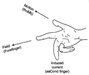
Fig. 6 Flemings right-hand rule Y= Ndi (eqn. 21)
Faraday's law says that the induced emf is given by dY v=-- dt
(eqn. 22)
The direction of the induced emf is given by Lenz's law, which says that the induced voltage is in the direction such that, if the voltage caused a current to flow in the wire, the magnetic field produced by this current would oppose the change in Y. The negative sign indicates the opposing nature of the emf.
A current flowing in a simple coil produces a magnetic field. Any change in the current will change the magnetic field, which will in turn induce a back-emf in the coil. The self-inductance or just inductance L (H) of the coil relates the induced voltage to the rate of change of current
dl v= L- dt (eqn. 23)
Two coils placed close together will interact. The magnetic field of one coil will link with the wire of the second. Changing the current in the primary coil will induce a voltage in the secondary coil, given by the mutual inductance M (H) a v, =M- dt
Placing the coils very close together, on the same former, gives close coupling of the coils. The magnetic flux linking the primary coil nearly all links the secondary coil.
The voltages induced in the primary and secondary are each proportional to their number of turns, so that and by conservation of energy, approximately (eqn. 25)
(eqn. 26)
A two-winding transformer consists of two coils wound on the same ferromagnetic core. An autotransformer has only one coil with tapping points. The voltage across each section is proportional to the number of turns in the section. Transformer action is described more fully in section 6.1.
Fig. 7 Series resistors
3. Circuits
3.1 DC circuits
DC power is supplied by a battery, dc generator or rectifying power supply from the mains. The power flowing in a dc circuit is the product of the voltage and current (eqn. 27)
2 p = VI = i2R = R
Power in a resistor is converted directly into heat.
...but their voltages must be added together (Fig. 7)
When two or more resistors are connected in series, they carry the same current (eqn. 28) v= vl+ m + v3 As a result, the total resistance is given by
(eqn. 29)
When two or more resistors are connected in parallel, they have the same voltage but their currents must be added together (Fig. 8)
Z=Il +n+n (eqn. 30)
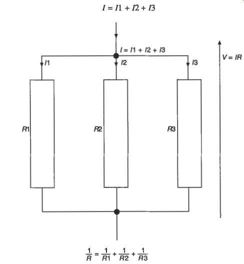
Fig. 8 Parallel resistors
The total resistance is given by:
(eqn. 31)
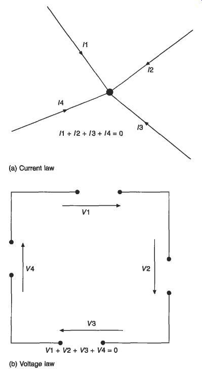
Fig. 9 Kirchhoff's laws
A complicated circuit is made of several components of brunches connected together at nodes forming one or more complete circuits, loops or meshes. At each node, Kirchhoff’s current law (Fig. 9(a)) says that the total current flowing into the node must be balanced by the total current flowing out of the node. In each loop, the sum of all the voltages taken in order around the loop must add to zero, by Kirchhoff's voltage law (Fig. 9(b)). Neither voltage nor current can be lost in a circuit.
DC circuits are made of resistors and voltage or current sources. A circuit with only two connections to the outside world may be internally complicated. However, to the outside world it will behave as if it contains some resistance and possibly a source of voltage or current. The Thevenin equivalent circuit consists of a voltage source and a resistor (Fig. 10(a)), while the Norton equivalent circuit consists of a current source and a resistor (Fig. 10(b)). The resistor equals the internal resistance of the circuit, the Thevenin voltage source equals the open-circuit voltage. and the Norton current source is equal to the short-circuit current.
Many circuits contain more than one source of voltage or current. The current flowing in each branch, or the voltage at each node, can be found by considering each source separately and adding the results. During this calculation by superposition, all sources except the one being studied must be disabled: voltage sources are short- circuited and current sources are open-circuited. In Fig. 11, each of the loop currents I1 and I2 can be found by considering each voltage source separately and adding the results, so that
I1 = I1a + I2b, and I2 = I2a + I2b.
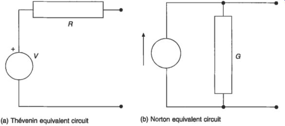
Fig. 10 Equivalent circuits--(a) Thevenin equivalent circuit (b) Norton
equivalent circuit
3.2 AC circuits
AC power is supplied by the mains from large ac generators or alternators, by a local alternator, or by an electronic synthesis. AC supplies are normally sinusoidal, so that at any instant the voltage is given by
(eqn. 32)
V,, is the peak voltage or amplitude, o is the angular frequency (rad s8) and @ the phase angle (rad). The angular frequency is related to the ordinary frequency f(Hz)
(eqn. 33)
and the period is 1/f.
The peak-to peak or pk-pk voltage is 2Vm, and the mot mean square or rms voltage is Vmax / radic. 2. It is conventional for the symbols V and Z in ac circuits to refer to the rms values, unless indicated otherwise. AC voltages and currents are shown diagrammatically on a phasor diagram (Fig. 12). It is convenient to represent ac voltages using complex numbers. A sinusoidal voltage can be written
(eqn. 34)
A resistor in an ac circuit behaves the same as in a dc circuit, with the current and voltage in phase and related by the resistance or conductance (Fig. 13). The current in an inductor lags the voltage across it by 90 deg. (d2 rad) (Fig. 14). The ac resistance or reactance X of an inductor increases with frequency x, = CUL (eqn. 35)
by The phase shift and reactance are combined in the complex impedance Z
V/1 = zL = jXL = jwL (eqn. 36)
Inductors in series behave as resistors in series
Ls = L1+ L2 + L3 (eqn. 37)
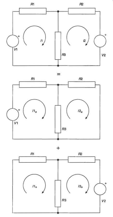
Fig. 11 Superposition
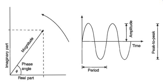
Fig. 12 Sinusoidal ac quantities
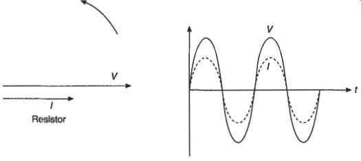
Fig. 13 Resistor in an ac circuit
... and inductors in parallel behave as resistors in parallel (eqn. 38)
For a capacitor, the current leads the voltage across it by 90" (1d2 rad) (Fig. 15). The reactance decreases with increasing frequency
Xc = 1/ wC (eqn. 39)
In a capacitor, the current leads the voltage, while in an inductor, the voltage leads the current.
The impedance is given by:
(eqn. 40)
Capacitors in series behave as resistors in parallel (eqn 41) and capacitors in parallel behave as resistors in series (eqn 42)
(eqn. 41)
Fig. 11 Inductor in an ac circuit
Fig. 15 Capacitor in an ac circuit
Cp = c1 + c2 + c3 (eqn. 42)
The direction of the phase shift in inductors and capacitors is easily remembered by the mnemonic CIVIL (i.e. C-IV, VI-L). Imperfect inductors and capacitors have some inherent resistance, and the phase lead or lag is less than 90". The difference between the ideal phase angle and the actual angle is called the loss angle 6. For a component of reactance X having a series resistance R
(eqn. 43)
R tan(6) = - X
The reciprocal of impedance is admittance
Z 1
-=y=- V Z
Combinations of resistors, capacitors and inductors will have a variation of impedance or admittance with frequency which can be used to select signals at certain frequencies in preference to others. The circuit acts as a filter; which can be low-pass, high-pass, band-pass, or band-stop.
An important filter is the resonant circuit. A series combination of inductor and capacitor has zero impedance (infinite admittance) at its resonant frequency
(eqn. 45)
A parallel combination of inductor and capacitor has infinite impedance (zero admittance) at the same frequency.
In practice a circuit will have some resistance (Fig. 16), which makes the resonant circuit imperfect. The quality factor Q of a series resonant circuit with series resistance R is given by e=(+) X =(%) w=wo e-0 and for a parallel circuit with shunt resistance:
(eqn. 46)
(eqn. 47)
A filter with a high Q will have a sharper change of impedance with frequency than one with a low Q, and reduced losses.
Mains electricity is generated and distributed using three phases. Three equal voltages are generated at 120 deg. phase intervals. The phase voltage V, is measured with respect to a common star point or neutral point, and the line voltage V, is measured between the separate phases. In magnitude,
v,= avp (eqn. 48)
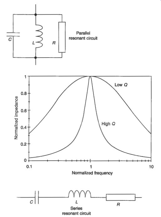
Fig. 16 Resonant circuits
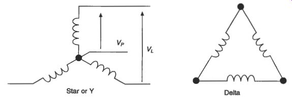
Fig. 17 Three-phase connections
Any three-phase generator, transformer or load can be connected in a star or Y configuration, or in a delta configuration (Fig. 17). 2.3.3 Magnetic circuits A reluctance in a magnetic circuit behaves in the same way as a resistance in a dc electric circuit. Reluctances in series add together
(eqn. 49)
…and for reluctances in parallel…
...or (eqn. 50).
Transformers and power reactors may contain no air gap in the magnetic circuit.
However, motors and generators always have a small air gap between the rotor and stator. Many reactors also have an air gap to reduce saturation of the ferromagnetic parts. The reluctance of the air gap is in series with the reluctance of the steel rotor and stator. The high relative permeability of steel means that the reluctance of even a small air gap can be much larger than the reluctance of the steel parts of the machine. For a total air gap g (m) in a magnetic circuit, the magnetic flux density B in the air gap is given approximately by...
(eqn. 51)
...where Nf is the number of series turns on the field winding of the machine, and If is the current in the field winding (Fig. 18).
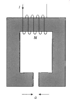
Fig. 18 Air-gap magnetic circuit.
4. Energy and power
4.1 Mechanical energy
According to Newton's third law of motion, mechanical force causes movement is a straight line, such that the force F (N) accelerates a mass m (kg) with acceleration a (m/s^2)
F=ma (eqn. 52)
Rotational movement depends in the same way upon torque T (N m) accelerating a moment of inertia J (kg . m^2) with angular acceleration alpha (rad^s2)
T= J alpha (eqn. 53)
Movement is often opposed by friction. Friction forces and torques always work against the movement. Friction between dry surfaces has a maximum value, depending on the contact force. Once the driving force exceeds the limiting friction force, the system will move and the friction force stays constant. Viscous damping gives a restraining force which increases with the speed. Friction between lubricated surfaces is mainly a viscous effect.
Objects store potential energy when they are lifted up. The stored energy W (J) of a mass m is proportional to the height h (m) above ground level when the acceleration due to gravity g = 9.81 m/s
W = mgh (eqn. 54)
Moving objects have kinetic energy depending on their linear speed v (m/s) or angular speed o (rads)
(eqn. 55)
Mechanical work is done whenever an object is moved a distance x (m) against an opposing force, or through an angle 8 (rad) against an opposing torque...
(eqn. 56)
Mechanical power P (W) is the rate of doing work...
P=Fv
(eqn. 57)
4.2 Electrical energy
In electrical circuits, electrical potential energy is stored in a capacitance C charged to a voltage V
1 w = -cv2 2 (eqn. 58)
...while kinetic energy is stored in an inductance L carrying a current I
(eqn. 59)
Capacitors and inductors store electrical energy
Resistors dissipate energy and convert it into heat. The power dissipated and lost to the electrical system in a resistor R has already been shown in eqn 27.
Electrical and mechanical systems can convert and store energy, but overall the total energy in a system is conserved. The overall energy balance in an electromechanical system can be written
W=-LZ2 1
electrical energy in + mechanical energy in
= electrical energy lost in resistance
+ mechanical energy lost in friction
+ magnetic energy lost in steel core
+ increase in stored mechanical energy
+ increase in stored electrical energy (eqn. 60)
The energy balance is sometimes illustrated in a power flow diagram (Fig. 19).
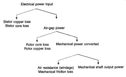
Fig. 19 Power flow diagram (example of a typical motor)
The overall efficiency of a system is the ratio of the useful output power to the total input power, in whatever form...
(eqn. 61)
In an ac circuit, the instantaneous power depends on the instantaneous product of voltage and current. For sinusoidal voltage and current waveforms, the apparent power S (VA) is the product of the rms voltage and the rms current.
s = VI (eqn. 62)
When the voltage waveform leads the current waveform by an angle @, the average, active or real power P(W) is P = VI cos(@) (eqn. 63)
The factor relating the real power to the apparent power is the power factor A a = cos(@) (eqn. 64)
The real power is converted into heat or mechanical power. In addition there is an oscillating flow of instantaneous power, which is stored and then released each cycle by the capacitance and inductance in the circuit. This imaginary or reactive power Q (VAr) is given by
Q = VI sin($) (eqn. 65)
By convention an inductive circuit (where the current lags the voltage) absorbs VAr, while a capacitive circuit (where the current leads the voltage) acts as a source of VAr. The relationship between S, P and Q is
S^2= P^2 + Q^2 (eqn. 66)
In a three-phase circuit, the total real power is the sum of the power flowing into each phase. For a balanced three-phase circuit with phase-neutral voltage Vp and phase current Ip the total power is the sum of the powers in each phase
P = 3 vpzp cos($) (eqn. 67)
In terms of the line voltage VL, the real power is...
P = fiVL zp cos( $) (eqn. 68)
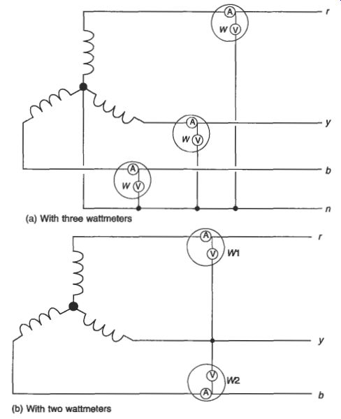
Fig. 20 Three-phase power measurement
Similar relations hold for the reactive and apparent power.
The power in a three-phase circuit can be measured using three wattmeters, one per phase, and the measurements added together (Fig. 20(a)). If it is known that the load is balanced, with equal current and power in each phase, the measurement can be made with just two wattmeters (Fig. 200)). The total power is then
w= WI + w, (eqn. 69)
The two wattmeter arrangement also yields the power factor angle (eqn. 70)
4.3 Per-unit notation
Power systems often involve transformers which step the voltage up or down.
Transformers are very efficient, so that the output power from the transformer is only slightly less than the input power. Analysis and design of the circuit is made easier if the circuit values are normalized, such that the normalized values are the same on both sides of the transformers. This is accomplished using the per-unit system. A given section of the power system operates at a certain base voltage VB. Across transformers the voltage steps up or down according to the turns ratio. The base voltage will be different on each side of the transformer. A section of the system is allocated a base apparent power rating or base VA V . AB. This will be the same on both sides of the transformer. Combining these base quantities gives a base impedance ZB and base current I, (eqn. 71)
The base impedance and base current change across a transformer.
All voltages and impedances in the system are normalized using the appropriate base value. The resulting normalized quantities are per-unit values. Once the circuit has been converted to per-unit values, the transformers have no effect on nominal tap position, and can be replaced by their own equivalent per-unit impedance.
The per-unit values are sometimes quoted as per cent values, by multiplying by 100 percent.
A particular advantage of the per-unit and per cent notation is that the resulting impedances are very similar for equipment of very different sizes.
4.4 Energy transformation effects
Most electrical energy is generated by electromagnetic induction. However, electricity can be produced by other means than electromagnetic induction. Batteries use electrochemistry to produce low voltages (typically 1-2 V). An electrolyte is a solution of chemicals in water such that the chemical separates into positively and negatively charged ions when dissolved. The charged ions react with the conducting electrodes and release energy, as well as giving up their charge (Fig. 21). A fixed electrode potential is associated with the reaction at each electrode; the difference between the two electrode potentials drives a current around an external circuit. The electrolyte must be sealed into a safe container to make a suitable battery. 'Dry' cells use an electrolyte in the form of a gel or thick paste. A primary cell releases electricity as the chemicals react, and the cell is discarded once all the active chemicals have been used up, or the electrodes have become contaminated. A secondary cell uses a reversible chemical reaction, so that it can be recharged to regenerate the active chemicals. The fuel cell is a primary cell which is constructed so that the active chemicals (fuel) pass through the cell, and the cell can be used for long periods by replenishing the chemicals. Large batteries consist of cells connected in series or parallel to increase the output voltage or current. The main types of primary, secondary and fuel cell are described in sections 12.2, 12.3 and 12.4, respectively.
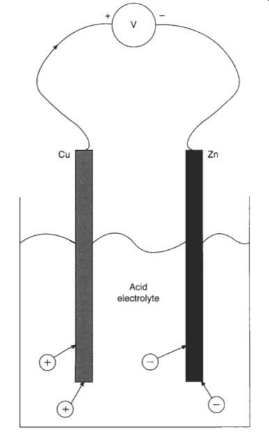
Fig. 21 Simple cell
Electricity can be generated directly from heat. When two different materials are used in an electrical circuit, a small electrochemical voltage (contact potential) is generated at the junction. In most circuits these contact potentials cancel out around the circuit and no current flows. However, the junction potential varies with temperature, so that if one junction is at a different temperature from the others, the contact potentials will not cancel out and the net circuit voltage causes current to flow (Seebeck effect). The available voltage is very small, but can be made more useful by connecting many pairs of hot and cold junctions in series. The thermocouple is used mostly for measurement of temperature by this effect, rather than for the generation of electrical power (Fig. 22). The efficiency of energy conversion is greater with semiconductor junctions, but metal junctions have a more consistent coefficient and are preferred for accurate measurements. The effect can be reversed with suitable materials, so that passing an electric current around the circuit makes one junction hotter and the other colder (Peltier effect). Such miniature heat pumps are used for cooling small components.
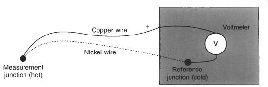
Fig. 22 A thermocouple (Seebeck effect)
Certain crystalline chemicals are made from charged ions of different sizes. When a voltage is applied across the crystal, the charged ions move slightly towards the side of opposite polarity, causing a small distortion of the crystal. Conversely, applying a force so as to distort the crystal moves the charged ions and generates a voltage.
This piezoelectric effect is used to generate high voltages from a small mechanical force, but very little current is available. The use of piezoelectric sensors for the measurement of mechanical pressure and force is described in section 4.42.
Ferromagnetic materials also distort slightly in a magnetic field. The magnetostrictive effect produces low frequency vibration (hum) in ac machines and transformers.
Electricity can be produced directly from light. The photovoltaic effect occurs when light falls on suitable materials, releasing electrons from the material and generating electricity. The magnitude of the effect is greater with short wavelength light (blue) than long wavelength light (red), and stops altogether beyond a wavelength threshold. Light falling on small photovoltaic cells is used for light measurement, communications and for proximity sensors. On a larger scale, semiconductor solar cells are being made with usable efficiency for power generation.
Light is produced from electricity in incandescent filament bulbs, by heating a wire to sufficiently high temperature that it glows. Fluorescent lights produce an electrical discharge through a low-pressure gas. The discharge emits ultraviolet radiation, which causes a fluorescent coating on the inside of the tube to glow.