AMAZON multi-meters discounts AMAZON oscilloscope discounts
1. Introduction
The performance of most types of electrical equipment (as opposed to electronic equipment) relies for their safe and efficient performance on an electrical circuit and the means to keep this circuit isolated from the surrounding materials and environment.
Many types of equipment also have a magnetic circuit, which is linked to the electrical circuit by the laws outlined in Section 2.
The main material characteristics of relevance to electrical engineering are therefore those associated with conductors for the electrical circuit, with the insulation system necessary to isolate this circuit, and with the specialized steels and permanent magnets used for the magnetic circuit.
Although other properties, e.g. mechanical, thermal and chemical, are also relevant, these are often important in specialized cases and coverage of these properties is best left to other books which address these areas more broadly. The scope of this Section is restricted to the main types and characteristics of conductors, insulation systems and magnetic materials which are used generally in electrical plant and equipment.
2. Magnetic materials
All materials have magnetic properties. These characteristic properties may be divided into five groups:
- diamagnetic
- paramagnetic
- ferromagnetic
- anti-ferromagnetic
- ferrimagnetic
Only the ferromagnetic and ferrimagnetic materials have properties that are useful in practical applications.
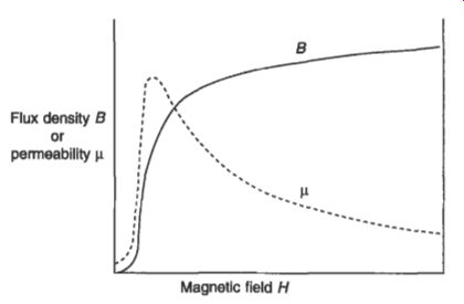
Fig. 1 Magnetization and permeability curves
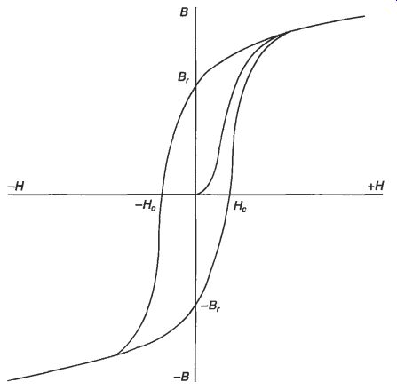
Fig. 2 Magnetization and hysteresis curves
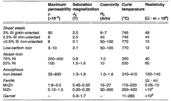
Table 1 Properties of soft magnetic materials
Ferromagnetic properties are confined almost entirely to iron, nickel and cobalt and their alloys. The only exceptions are some alloys of manganese and some of the rare earth elements.
Ferro-magnetism is the magnetism of the mixed oxides of the ferromagnetic elements.
These are variously called ferrites and garnets. The basic ferrite is magnetite, or Fe3O4, which can be written as FeO.FeO3. By substituting for the FeO with other divalent oxides, a wide range of compounds with useful properties can be produced.
The main advantage of these materials is that they have high electrical resistivity which minimizes eddy currents when they are used at high frequencies.
The important parameters in magnetic materials can be defined as: permeability -- this is the flux density B per unit of magnetic field H, as defined in eqs 2.14 and 2.15. It is usual and more convenient to quote the value of relative permeability pr, which is B/poH. A curve showing the variation of permeability with magnetic field for a ferromagnetic material is given in Fig. 1. This is derived from the initial magnetization curve and it indicates that the permeability is a variable which is dependent on the magnetic field.
The two important values are the initial permeability, which is the slope of the magnetization curve at H = 0, and the maximum permeability, corresponding to the knee of the magnetization curve.
0 saturation - when sufficient field is applied to a magnetic material it becomes saturated. Any further increase in the field will not increase the magnetization and any increase in the flux density will be due to the added field. The saturation magnetization is M, in Ah and J, or B, in tesla.
remanence, B, and coercivity, H,- these are the points on the hysteresis loop shown in Fig. 2 at which the field H is zero and the flux density B is zero, respectively. It is assumed that in passing round this loop the material has been saturated. If this is not the case, then an inner loop is traversed with lower values of remanence and coercivity.
--Ferromagnetic and ferrimagnetic materials are characterized by moderate to high permeabilities, as shown in Table 1. The permeability varies with the applied magnetic field, rising to a maximum at the knee of the B-H curve and reducing to a low value at very high fields. They also exhibit magnetic hysteresis whereby the intensity of magnetization of the material varies according to whether the field is being increased in a positive sense or decreased in a negative sense, as shown in Fig. 2. When the magnetization is cycled continuously round a hysteresis loop, as for example when the applied field arises from an alternating current, there is an energy loss proportional to the area of the included loop. This is the hysteresis loss, and it is measured in joules/m^3. High hysteresis loss is associated with permanent magnetic characteristics exhibited by materials commonly termed 'hard' magnetic materials, as these often have hard mechanical properties. Those materials with low hysteresis loss are termed soft and are difficult to magnetize permanently.
Ferromagnetic or ferrimagnetic properties disappear reversibly if the material is heated above the Curie temperature, at which point it becomes paramagnetic, that is effectively non-magnetic.
2.1 Soft (high-permeability) materials
There is a wide variety of soft magnetic materials for applications from constant dc field through 50 Hz up to microwave frequencies. For the bulk of applications iron, steel or cast iron are used. They have the advantage of low cost and strength, but they should only be used for dc applications since they have low electrical resistivity which would result in eddy currents if used in alternating fields.
In choosing a high-permeability material for a particular application there may be special considerations and the following is a guide to the choice. If the frequency of the applied voltage is 10 kHz or above then ferrites or garnets will normally be used.
For constant-field applications mild steel will be used, or low-carbon iron where the highest permeability or lowest coercivity is needed. For 50 Hz power transformers, grain-oriented silicon steel is used but there is now serious competition from amorphous strip and although this is more expensive the core loss is significantly lower than that of silicon steel. For the highest permeability and lowest coercivity in specialist applications up to about 10 kHz nickel iron would be the preferred choice although its cost may be prohibitive.
2.1.1 Sheet steels
There are a number of grades of sheet steel and these comprise by far the greatest part of the soft, high-permeability material which is used. These metallic materials have a comparatively low electrical resistivity and they are used in sheet (or lamination) form because this limits the flow of eddy currents and the losses which result. The range of sheet thickness used for 50 or 60 Hz applications is 0.35-0.65 mm for non- oriented materials and 0.13-0.35 mm for grain-oriented silicon steels. For higher frequencies of 400-1000 Hz thicknesses of 0.05-0.20 mm are used.
In grain-oriented steel an increasing level of silicon content reduces the losses but also reduces the permeability; for many applications a 3 per cent silicon content represents a good balance. The effect of the silicon is to increase the electrical resistivity of the steel; not only does this reduce eddy current losses but it also improves the stability of the steel and aids the production of grain orientation. The sheet is subject to cold rolling and a complex annealing treatment to produce the grain orientation in the rolling direction and this also gives improved magnetic permeability in that direction. The properties are further improved at the annealing stage with a glass film on the surface which holds the steel in a state of tension and provides electrical insulation between laminations in a core. A phosphate coating is applied to complete the tensioning and insulation. The grain size in the resulting sheets is comparatively large and the domain boundaries are quite widely spaced.
Artificial grain boundaries can be produced by laying down lines of ablated spots on the steel surface; this gives a stress and atomic disruption pattern which pins domain walls and leads to a smaller wall spacing. Various methods have been used to produce this ablating, including spark and laser techniques. All these processes are applied within the steel manufacturer's works and the resulting steel is often referred to as fully processed. The main application of this grain-oriented material is in power transformers where low power loss is important, since the transformer is always connected even when its loading is at a minimum.
For rotating machinery, especially motors rated more than about 100 kW. non- oriented steels with a lower silicon content are used. Whilst efficiency remains important in this application, high permeability is now also important in order to minimize magnetizing current and to maximize torque. This material is also used in smaller transformers, chokes for fluorescent tubes, meters and magnetic shielding.
For smaller motors silicon-free non-oriented steels are often used. These are produced by the steel manufacturer with a relatively high carbon content. The carbon makes the sheet sufficiently hard for punching into laminations and after punching the material is decarburized and annealed to increase the grain size. Because of the need for this secondary processing the materials are often known as semi- processed. These materials are generally cheaper than silicon steels but in their finished form they have a much higher permeability; in small motors particularly this can be more important than efficiency. Other applications include relays and magnetic clutches.
Silicon steels are also produced in the form of bars, rods or wires for relays, stepping motors and gyroscope housings. The tensile strength of the silicon steels may be improved by the addition of alloying elements such as manganese; this type of material is used in highly stressed parts of the magnetic circuit in high-speed motors or generators.
2.1.2 Amorphous alloys
This class of alloys, often called metallic glasses, is now an established group of soft magnetic materials. The materials are produced by rapid solidification of the alloy at cooling rates of about a million degrees centigrade per second. The alloys solidify with a glass-like atomic structure which is a non-crystalline frozen liquid. The rapid cooling is achieved by causing the molten alloy to flow through an orifice onto a rapidly rotating water-cooled drum. This can produce sheets as thin as 10 pm and a meter or more wide.
There are two main groups of amorphous alloys. The first is the iron-rich group of magnetic alloys, which have the highest saturation magnetization among the amorphous alloys and are based on inexpensive raw materials. Iron-rich alloys are currently being used in long-term tests in power transformers in the USA. The second is the cobalt-based group. which has very low or zero magnetostriction, leading to the highest permeability and the lowest core loss. Cobalt-based alloys are used for a variety of high-frequency applications including pulsing devices and tape recorder heads, where their mechanical hardness provides excellent wear resistance.
All of these alloys have a resistivity which is higher than that of conventional crystalline electrical steels. Because of this, eddy current losses are minimized both at 50 Hz and at higher frequencies. The alloys have other advantages including flexibility without loss of hardness, high tensile strength and better corrosion resistance than similar crystalline materials.
2.1.3 Nickel-iron alloys
The very high magnetic permeability and low coercivity of nickel-iron alloys are due to two fundamental properties, which are magnetostriction and magnetic anisotropy.
At a nickel content of about 78 per cent both of these parameters are zero.
Magnetostriction has been briefly referred to in section 2.4.4; it is the change of dimensions in a material due to magnetization, and when this is zero there are no internal stresses induced during magnetizing. Magnetic anisotropy is the difference between magnetic behavior in different directions; when this is zero the magnetization increases steeply under the influence of a magnetic field, independent of crystal direction. The alloys with about 78 per cent nickel content are variously called Mumetal or Permalloy.
The commercial alloys in this class have additions of chromium, copper and molybdenum in order to increase the resistivity and improve the magnetic properties.
Applications include special transformers, circuit breakers, magnetic recording heads and magnetic shielding.
Fifty per cent nickel-iron alloys have the highest saturation magnetization of this class of materials, and this results in the best flux-carrying capacity. They have a higher permeability and better corrosion resistance than silicon iron materials, but they are more expensive. A wide range of properties can be produced by various processing techniques. Severe cold reduction produces a cube texture and a square hysteresis loop in annealed strip. The properties can also be tailored by annealing the material below the Curie temperature in a magnetic field. Applications for this material include chokes, relays and small motors.
2.1.4 Ferrites and garnets
Ferrites are iron oxide compounds containing one or more other metal oxide. The important high magnetic permeability materials are manganese zinc ferrite and nickel zinc ferrite. They are prepared from the constituent oxides in powder form, preferably of the same particle size intimately mixed. The mixture is fired at about 1000°C and this is followed by crushing, milling and then pressing of the powder in a die or extrusion to the required shape. The resulting compact is a black brittle ceramic and any subsequent machining must be by grinding. The materials may be prepared with high permeability, and because their high electric resistivity limits eddy currents to a negligible level they can be used at frequencies up to 20 MHz as the solid core of inductors or transformers.
A combination of hysteresis, eddy current and residual losses occurs, and these components may be separately controlled by composition and processing conditions, taking into account the required permeability and the working frequency.
The saturation flux density of ferrites is relatively low, making them unsuitable for power applications. Their use is therefore almost entirely in the electronic and telecommunications industry where they have now largely replaced laminated alloy and powder cores.
Garnets are used for frequencies of 100 MHz and above. They have resistivities in excess of lo8 S2 . m compared with ferrite resistivity which is up to lo3 &2 . m.
Since eddy current losses are limited by resistivity, they are greatly reduced in garnets. The basic Yttrium-Iron Garnet (YIG) composition is 3Y203 - 5Fe203.
This is modified to obtain improved properties such as very low loss and greater temperature stability by the addition of other elements including A1 and Gd. The materials are prepared by heating of the mixed oxides under pressure at over 1300°C for up to 10 hours. Garnets are used in microwave circuits in filters, isolators, circulators and mixers.
2.7.5 Soft magnetic composites
These composites (SMC) consist of iron or iron alloy powder mixed with a binder and a small amount of lubricant. The composite is pressed into the final shape which can be quite complex. The lubricant reduces the friction during pressing and aids the ejection of the part from the die. After pressing the parts are either cured at 150 to 275°C or heat treated at 500°C. The isolation of the particles within the binder minimizes the eddy currents and makes the components very suitable for medium frequency applications up to 1 kHz or more. They have the added advantages of being isotropic and can be used for components with quite complex shapes.
2.2 Hard (permanent magnet) materials
The key properties of a permanent magnet material are given by the demagnetization curve, which is the hysteresis curve in the second quadrant between B, and -H,. It can be shown that when a piece of permanent magnet material is a part of a magnetic circuit, the magnetic field generated in a gap in the circuit is proportional to B x H x V, where B and H represent a point on the demagnetization curve and V is the volume of permanent magnet. To obtain a given field with a minimum volume of magnet the product B x H must therefore be a maximum, and the (BH),,, value is useful in comparing material characteristics.
The original permanent magnet materials were steels, but these have now been superseded by better and more stable materials including Alnico, ferrites and rare earth alloys. The magnetic properties of all the permanent magnet materials are summarized in Table 2.
2.2.7 Alnico alloys
A wide range of alloys with magnetically useful properties is based on the Al-Ni- Co-Fe system. These alloys are characterized by high remanence, high available energy and moderately high coercivity. They have a low and reversible temperature coefficient of about -0.02 percent/OC and the widest useful temperature range (up to over 500°C) of any permanent magnet material.
The alloys are produced either by melting or sintering together the constituent elements. Anisotropy is achieved by heating to a high temperature and allowing the material to cool at a controlled rate in a magnetic field in the direction in which the magnets are to be magnetized. The properties are much improved in this direction at the expense of properties in the other directions. This is followed by a tempering treatment in the range 650-550 C. A range of coercivities can be produced by varying the cobalt content. The properties in the preferred direction may be further improved by producing an alloy with columnar crystals.
2.2.2 Ferrites
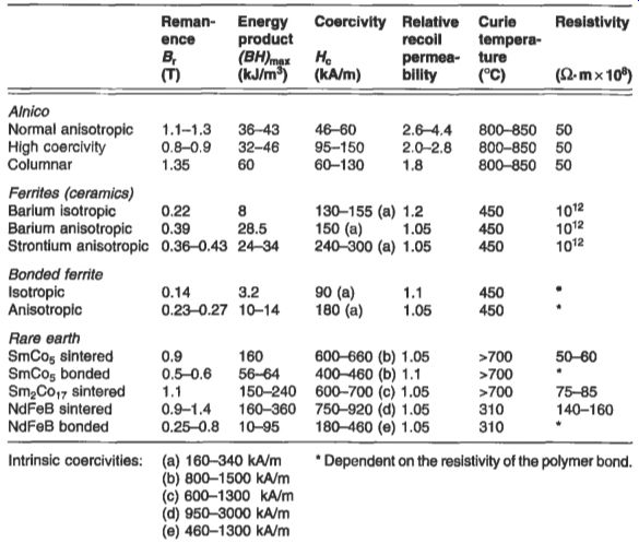
Table 2 Characteristics of permanent magnet materials
The permanent magnet ferrites are also called ceramics and they are mixtures of ferric oxide and an oxide of a divalent heavy metal, usually barium or strontium.
These ferrites are made by mixing together barium or strontium carbonate with iron oxide. The mixture is fired and the resulting material is milled to a particle size of about 1 p. The powder is then pressed to the required shape in a die and anisotropic magnets are produced by applying a magnetic field in the pressing direction. The resulting compact is then fired.
2.2.3 Rare earth alloys
The (BH), values that can be achieved with rare earth alloys are 4-6 times greater than those for Alnico or ferrite.
There are three main permanent magnet rare earth alloys, two of which (SmCo5 and Sm2Col,) are based on samarium and cobalt, the other being neodymium iron boron (NdFeB). These materials may be produced by alloying the constituent elements together, or more usually by reducing a mixture of the oxides together in a hydrogen atmosphere using calcium as the reducing agent. The alloy is then milled to a particle size of about 10 pm, pressed in a magnetic field and sintered in vacuum.
SmCo5 was the first alloy to be available, but this has gradually been replaced by Sm2Col7 because of its lower cost and better temperature stability. The more recently developed NdFeB magnets have the advantage of higher remanence B, and higher (BH)mau, and they are lower in cost because the raw materials are cheaper. The disadvantage of NdFeB materials is that they are subject to corrosion and they suffer from a rapid change of magnetic properties (particularly coercivity) with temperature.
Corrosion can be prevented by coating the magnets and the properties at elevated temperature may be improved by small additions of other elements.
2.2.4 Bonded magnets
Ferrites and rare earth magnets are also produced in bonded forms. The magnet powder particles are mixed with the bond and the resulting compact can be rolled, pressed or injection molded. For a flexible magnet the bonds may be rubber: or for a rigid magnet they may be nylon, polypropylene, resin or other polymers. Although the magnetic properties are reduced by the bond, they can be easily cut or sliced and in contrast to the sintered magnets they are not subject to cracking or chipping.
Rolled or pressed magnets give the best properties as some anisotropy may be induced.
but injection molding is sometimes preferred to produce complex shapes which might even incorporate other components. Injection molding also produces a precise shape with no waste of material.
2.2.5 Applications
Permanent magnets have a very wide range of applications and virtually every part of industry and commerce uses them to some extent. At one time Alnico was the only available high-energy material, but it has gradually been replaced by ferrites and rare earth alloys except in high-stability applications. Ferrites are much cheaper than Alnico but because of their lower flux density and energy product a larger magnet is often required. However, about 70 per cent of magnets used are ferrite. They find bulk applications in loudspeakers, small motors and generators and a wide range of electronic applications. The rare earth alloys are more expensive but despite this and because of their much greater strength they are being used in increasing quantities.
They give the opportunity for miniaturization, the 'Walkman' portable stereo player being an example. Figures 3.3 and 3.4 show the range of applications for permanent magnets in the home and in a car.
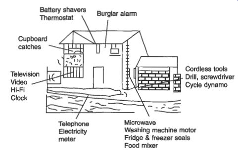
Fig. 3 Magnets in the home
-----------
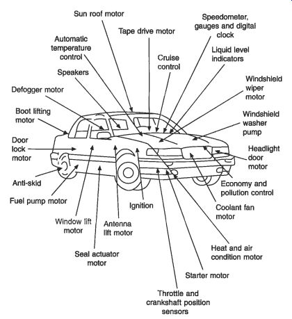
Fig. 4 Magnets in the car
---------
2.3 Other materials
In addition to the two main groups of soft and hard magnetic materials there are other materials which meet special needs.
The feebly magnetic steels are austenitic, and their virtually non-magnetic properties are achieved by additions of chromium and nickel to a low-carbon steel. To attain a relative permeability of 1.05 or less the recommended composition is 18 per cent chromium and 10 per cent nickel, or greater. These steels, which have minimum strength requirements, are used for non-magnetic parts of machinery, for magnetic measuring equipment and for minesweeping equipment, where magnetic flux can actuate magnetic mines.
Magnetic recording makes use of fine magnetic particles which are embedded in the tape or disc. These particles are of metal or of iron or chromium oxide and the choice depends on a compromise between price and quality. The heads used for magnetic recording are usually made from high-permeability ferrites, but amorphous metal is now also being used. Magnetic storage is a rapidly expanding area with higher and higher information densities being achieved.
2.4 Standards
The main international standard for magnetic materials is IEC 60404, to which BS 6404 is equivalent. This standard has many parts with specifications for the properties of silicon steels, nickel irons and permanent magnets. Also included are measurement standards for these materials.
3. Insulating materials
The reason for using insulating materials is to separate electrically the conducting parts of equipment from each other and from earthed components. Earthed components may include the mechanical casing or structure that is necessary to enable the equipment to be handled and to operate. Whereas the 'active' parts of the equipment play a useful role in its operation, the insulation is in many ways a necessary evil. For example. in an electric motor the copper of the winding and the steel core making up the magnetic circuit are the active components and both contribute to the power output of the motor; the insulation which keeps these two components apart contributes nothing, in fact it takes up valuable space and it may be considered by the designer as not much more than a nuisance.
For these reasons, insulating materials have become a design focus in many types of electrical equipment, with many companies employing specialists in this field and carrying out sophisticated life testing of insulation systems. Such is the importance attached to this field that major international conferences on the subject are held regularly, for instance by the IEEE in USA and by IEE and BEAMA in the UK. The simplest way to define an insulating material is to state what it is not. It is not a good conductor of electricity and it has a high electrical resistance that decreases with rising temperature, unlike conductors. The following are the most important properties of insulating materials:
volume resistivity, which is also known as specific resistance
re1ativepermirri~~it;v (or dielectric constant), which is defined as the ratio of the electric flux density produced in the material to that produced in a vacuum by the same electric field strength. The definitions have been set down in eqs 2.1 and 2.2. Relative permittivity can be expressed as the ratio of the capacitance of a capacitor made of that material to that of the same capacitor using a vacuum as its dielectric (see eqn 2.11).
dielectric loss (or electrical dissipation factor), which is defined as the ratio of the power loss in a dielectric material to the total power transmitted through it. It is given by the tangent of the loss angle and is commonly known as tan delta. Tan delta has been defined in eqn 2.43.
The volume resistivity, relative permittivity and tan delta values for a range of insulating materials are shown in Table 3.
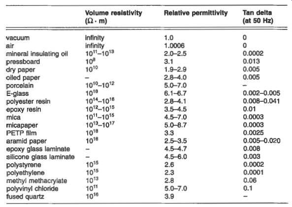
Table 3 Representative properties of typical insulating materials
The most important characteristic of an insulating material is its ability to withstand electric stress without breaking down. This ability is sometimes known as its dielectric strength. and is usually quoted in kV/mm. Typical values may range from 5 to 100 kV/mm, but it is dependent on a number of other factors which include the speed of application of the electric field, the length of time for which it is applied, temperature and whether ac or dc voltage is used.
Another significant aspect of all insulating materials that dominates the way in which they are categorized is the maximum temperature at which they will perform satisfactorily. Generally speaking, insulating materials deteriorate more quickly at higher temperatures and the deterioration can reach a point at which the insulation ceases to perform its required function. This characteristic is known as ageing, and for each material it has been usual to assign a maximum temperature beyond which it is unwise to operate if a reasonable life is to be achieved. The main grading or classes of insulation as defined in IEC 60085 and its UK equivalent BS 2757 are listed in Table 4. Where a thermal class is used to describe an item of electrical equipment, it normally represents the maximum temperature found within that product under rated load and other conditions. However, not all the insulation is necessarily located at the point of maximum temperature, and insulation with a lower thermal classification may be used in other parts of the equipment.
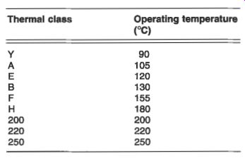
Table 4 Thermal classes for insulation
The ageing of insulation depends not only on the physical and chemical properties of the material and the thermal stress to which it is exposed, but also on the presence and degree of influence of mechanical, electrical and environmental stresses. The processing of the material during manufacture and the way in which it is used in the complete equipment may also significantly affect the ageing process. The definition of a useful lifetime will also vary according to the type and usage of equipment; for instance the running hours of a domestic appliance and a power station generator will be very different over a 25-year period. All of these factors should therefore influence the choice of insulating material for a particular application.
There is therefore a general movement in the development of standards and methods of testing for insulating materials towards the consideration of combinations of materials or insulating systems, rather than focusing on individual materials. It is not uncommon to consider life testing in which more than one form of stress is introduced; this is known as multifunctional or multifactor testing.
Primary insulation is often taken to mean the main insulation, as in the PVC coating on a live conductor or wire. Secondary insulation refers to a second 'line of defense' which ensures that even if the primary insulation is damaged, the exposed live component does not cause an outer metal casing to become live. Sleeving is frequently used as a secondary insulation.
Insulating materials may be divided into basic groups which are solid dielectrics, liquid dielectrics, gas and vacuum. Each is covered separately in the following sections.
3.1 Solid dielectrics
Solid dielectric insulating materials have in the past (for instance in BS 5691 part 2) been subdivided into three general groups: solid insulation of all forms not undergoing a transformation during application solid sheet insulation for winding or stacking, obtained by bonding superimposed layers insulation which is solid in its final state, but is applied in the form of a liquid or paste for filling, varnishing or bonding A more convenient and up-to-date way to subdivide this very large group of materials is used by the IEC Technical Committee 15: Insulating Materials:
inorganic (ceramic and glass) materials
plastic films
flexible insulating sleeving
rigid fibrous reinforced laminates
resins and varnishes
pressure-sensitive adhesive tapes
cellulosic materials
combined flexible materials
mica products
This subdivision is organized on the basis of application and is therefore more helpful to the practicing engineer. A brief description of each of these classes of material is given in the following sections.
3.1.1 Inorganic (ceramic and glass) materials
A major application for materials in this category is in high-voltage overhead lines as suspension insulators (see Figs 14.2 and 14.8), or as bushings on high-voltage transformers and switchgear (see Fig. 6.14). In either case the material is formed into the well-known series of flanged discs to increase the creepage distance along the surface of the complete insulator. Ceramic materials are used for a number of reasons including: ease of production of a wide range of shapes e good electrical breakdown strength retention of insulating characteristics in the event of surface damage.
3.1.2 Plastic films
Materials such as polyethylene terephthalate (PETP, more commonly referred to as polyester), polycarbonate, polyimide and polyethylene naphthalate (PEN) have been used as films in a variety of applications such as the insulation between foils in capacitors, slot insulation in rotating electrical machines (either by themselves or as a composite with other sheet materials) and more recently as a backing for mica- based products used in the insulation of high-voltage equipment. Plastic films are used in applications requiring dimensional stability, high dielectric strength, moisture resistance and physical toughness.
3.1.3 Flexible insulating sleeving
This fulfils a number of requirements including the provision of primary or secondary electrical insulation of component wiring, the protection of cables and components from the deleterious effects of mechanical and thermal damage, and as a rapid and low-cost method of bunching and containing cables. Sleevings may find application in electrical machines, transformers, domestic and heating appliances, light fittings, cable connections, switchgear and as wiring harnesses in domestic appliances and in vehicles. They are used because of their ease of application, flexibility and high dielectric strength; they lend themselves to an extremely wide range of formats including shrink sleeving, expandable constructions and textile-reinforced grades for low and high voltage and temperatures across the range -70°C to +450"C.
3.1.4 Rigid fibrous reinforced laminates
In the manufacture of most electrical equipment there is a need for items machined out of solid board or in the form of tubes and rods. These items can take the form of densified wood or laminates of paper, woven cotton, glass or polyester, or glass or polyester random mats laminated together with a thermosetting resin which might be phenolic, epoxy, polyester, melamine, silicone or polyimide, depending upon the properties required. Rigid boards are used because they are capable of being machined to size, and they retain their shape and properties during their service life, unlike unseasoned timber which was used in early equipment.
3.1.5 Resins and varnishes
In addition to their use in the laminates outlined in section 3.3.1.4, a wide range of varnishes and resins are used by themselves in the impregnation and coating of electrical equipment in order to improve its resistance to working conditions, to enhance its electrical characteristics and to increase its working life. At first many resins and varnishes were based on naturally occurring materials such as bitumen, shellac and vegetable oils, but now they are synthetically produced in a comprehensive range of thermoplastic, thermosetting and elastomeric forms. The more common types are phenolic, polyester, epoxy, silicone and polyimide, and these can be formulated to provide the most suitable processing and the required final characteristics. Varnishes and resins are used because of their ability to impregnate, coat and bond basic insulating materials; this assists in the application of the insulating materials and it significantly improves their service life and their ability to withstand dirt and moisture.
3.1.6 Pressure-sensitive adhesive tapes
Certain types of pressure-sensitive adhesive (PSA) tapes have become so much a part of modern life that the trade names have been absorbed into everyday language.
The usefulness of PSA in short lengths for holding down, sealing or locating applies equally in the field of insulation and a range of tapes has been developed which is based on paper, film or woven glass cloth, coated with suitable adhesive such as rubber, silicone or acrylic.
3.1.7 Cellulosic materials
Materials in the form of papers, pressboards and press papers continue to play a vital role in oil-filled power transformers. Included in this area are other materials which are produced by paper-making techniques, but which use aramid fibers; these materials have found wide application in high-temperature and dry-type transformers as well as in other types of electrical equipment. Cellulose materials are mainly used in conjunction with oil, and it is their porous nature that lends itself to successful use in transformers and cables.
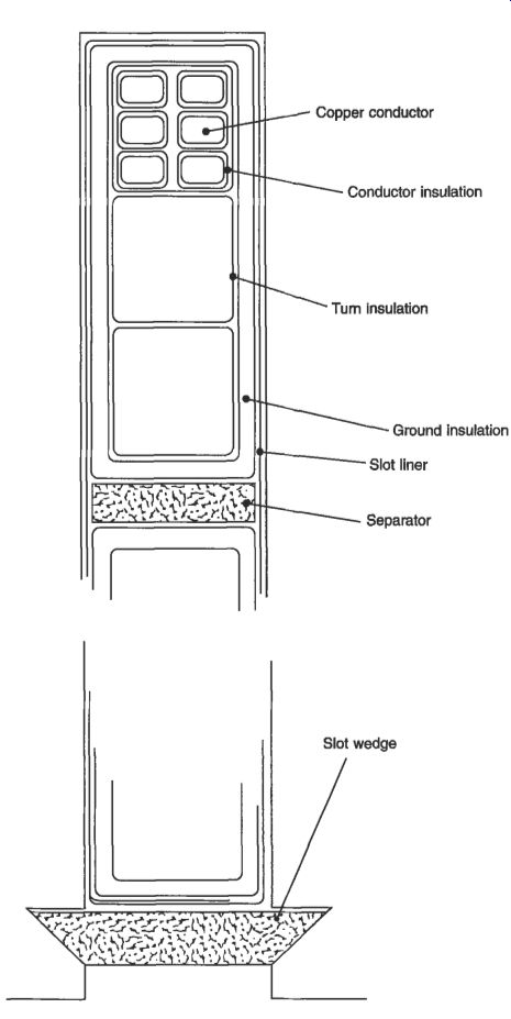
Fig. 5 Stator coil section of a high-voltage electrical machine
3.1.8 Combined flexible materials
In order to produce suitable materials with the required properties such as tear strength, electric strength and thermal resistance at an acceptable price, a range of laminated or combined flexible sheet products has been developed. These employ cellulosic, aramid and glass fleeces as well as other materials, in combination with many of the plastic films already referred to, in a range of forms to suit the application.
These products are used in large quantities in low-voltage electric motors.
3.1.9 Mica products
Materials based on mica, which is a naturally occurring mineral, play a central part in the design and manufacture of high-voltage rotating machines. Originally the material was in the form of mica splittings, but at present the industry uses predominantly mica-paper, which is produced by breaking down the mica into small platelets by chemical or mechanical means, producing a slurry and then feeding this through a traditional paper-making machine. The resulting micapaper, when suitably supported by a woven glass or film backing and impregnated with epoxy or a similar resin, is used to insulate the copper bars which make up the stator winding of the machine.
Micapaper is used in the ground insulation of the winding which is shown as part of the stator slot section illustrated in Fig. 5.
Micapaper is available in a resin-rich form, in which all the necessary resin for consolidation of the insulation around the winding is included within the material.
This consolidation is usually carried out in large steam or electrically heated processes into which an insulated coil side or bar can be placed; heat and pressure are then applied as necessary to cure fully the resin-rich micapaper insulation. Alternatively it is available for use with vacuum pressure impregnation (VPI), in which most of the resin is introduced after winding the machine. The use of VPI eliminates the need to consolidate the insulation in a press; consolidation is achieved either by the use of hydrostatic forces or by ensuring full impregnation of the bars or coils already placed or wound into slots. A large electrical machine stator is shown being lowered into a VPI tank in Fig. 6.
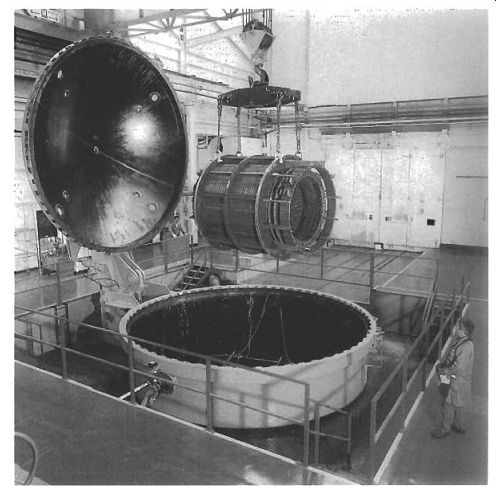
Fig. 6 A large vacuum and pressure impregnation facility capable of
treating stators up to 100 MVA
Mica-based products dominate high-voltage insulation systems because of their unique combination of properties, which include:
high dielectric strength
low dielectric loss at high frequency
high surface and volume resistivity
excellent resistance to corona discharge and electric arc erosion
temperature capability from -273°C to 1000°C
flame resistance
excellent chemical resistance
high resistance to compressive forces
3.1.10 Textile insulation
Although the use of fully varnished fabric is becoming less common, products using glass and polyester-based yarn, and to a lesser extent cotton and rayon, are still in use.
A much larger range of unvarnished narrow-fabric products, more commonly called woven tapes, exist and these use a variety of combinations of different glass and polyester yams tailored to meet specific applications. Primarily these tapes are used for finishing on top of other insulation such as micapaper, in order to provide a tough outer surface which can readily be coated with a final varnish or paint finish. When manufactured on modern shuttle-less looms they are an economic proposition.
Woven tapes are used because of their ease of application, good conformity and bedding down. An example of the complex shapes that they can be used to cover is shown in Fig. 7, which illustrates the end winding of a high-voltage electrical machine.
3.1.11 Elastomers and thermoplastics
There is a very wide range of polymeric and rubber-like insulation materials. These have traditionally been dealt with in connection with electric cables and IEC and BSI reflect this by dealing with them separately in Technical Committee 20: Electrical Cables. Some elastomers such as silicone have found application in sleeving, traction systems and increasingly as overhead line insulators, but the bulk of their application continues to be related to cables. The leading materials such as PVC, MDPE, XLPE and EPR are therefore referred to in Section 9.
3.2 Liquid dielectrics
A liquid dielectric remains in the liquid state throughout its working life, unlike resins and varnishes which become solid after processing.
The principal uses of liquid dielectrics are as a filling and cooling medium for transformers, capacitors and rheostats, as an arc-quenching medium in switchgear and as an impregnant of absorbent insulation used mainly in transformers, switchgear, capacitors and cables. The important properties of dielectric liquids are therefore electric strength, viscosity, chemical stability and flashpoint.
Typical materials include highly refined hydrocarbon mineral oils obtained from selected crude petroleum, silicone fluids, synthetic esters and hydrocarbons with high molecular weight. A specially interesting material for cables has been the waxy Mineral Insulating Non-Draining (MIND) compound which has been used in paper- insulated cables; this is described in section 9.2.3. A group of polychlorinated biphenyls (PCBs) has been used in transformers, but these materials are now being replaced and carefully disposed of because of their toxic nature and their resistance to biological and chemical degradation.
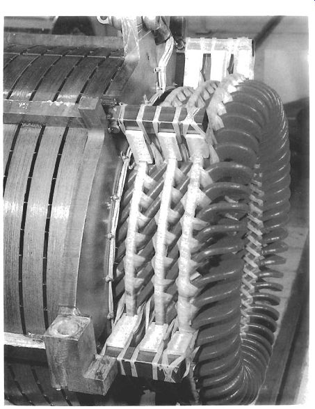
Fig. 7 Stator end winding bracing system for a 4-pole. 11 kV, 8 MW induction
motor.
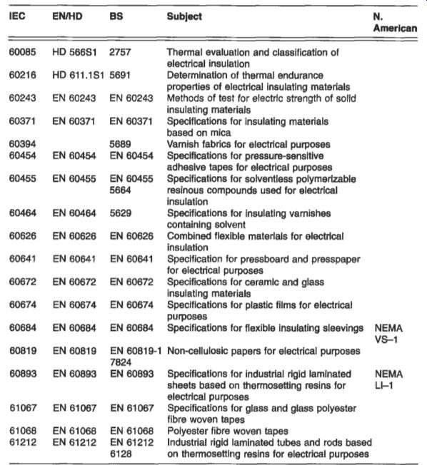
Table 5 National and international standards relating to insulating
materials
3.3 Gas insulation
Two gases already in common use for insulation are nitrogen and sulphur hexafluoride (SF6). Nitrogen is used as an insulating medium in some sealed transformers, while SF6 is finding increasing use in transmission and distribution switchgear because of its insulating properties and its arc-extinguishing capabilities; this is described further in sections 7.4.1 and 7.5.3(b).
3.4 Vacuum insulation
Vacuum insulation is now used in a range of medium-voltage switchgear. Like SF6, it has both insulating and arc-extinguishing properties. The action of the vacuum in a circuit breaker is explained in section 7.4.1.
3.5 Standards
A selection of national and international standards covering the insulation field is given in Table 5. The majority of the IEC standards with their EN and BSEN equivalents consist of three parts:
Part 1: Definitions, classification and general requirements Part 2: Methods of test Part 3: Specifications for individual materials
4. Conducting materials
Strictly, conducting materials fall into three groups, which are conductors, semiconductors and imperfect insulators. Insulators have been covered in section 3.3, so the focus here is on conductors and semiconductors.
4.1 Conductors
In general, metals and alloys are conductors of electricity. The conductivity in metals such as copper and aluminum is due to electrons which are attracted to the positive terminal when a voltage is applied. The freedom with which the electrons can move determines the conductivity and resistivity. The restraints on electron movements are impurities, stresses and thermal lattice vibrations, so to obtain the highest conductivity the metal must be very pure and in the annealed state. With increasing temperature the thermal lattice vibrations increase and conductivity is therefore reduced.
The principal materials for commercial application as conductors are the pure metals aluminum and copper, although very widely used are the alloys of these metals, with small additions of other elements to improve their properties for particular applications. Table 6 compares typical values of the key parameters for the two metals.
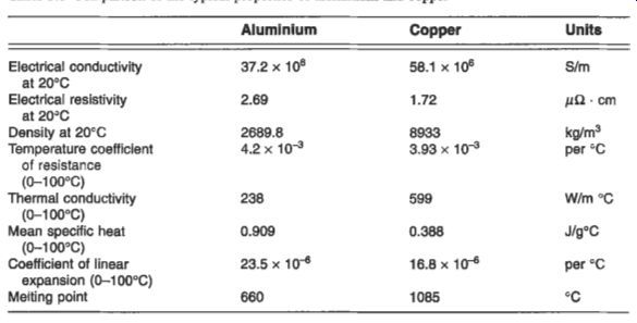
Table 6 Comparison of the typical properties of aluminum and copper

Table 7 IEC and BSI recommended sizes of annealed copper wires
4.1.1 Copper and its alloys
Copper has the highest electrical and thermal conductivity of the common industrial metals. It has good mechanical properties, is easy to solder, is readily available and has high scrap value. It is widely used in wire form, and Table 7 gives information for the commonly used wire sizes.
The electrical resistance of copper, as of all other pure metals, varies with temperate.
The variation is sufficient to reduce the conductivity of pure copper at 100°C to about 76 per cent of its value at 20°C. The resistance RtI at temperature rI is given by the relationship
R~I = Rr[1 + ar(tl - t)l (3.1)
where CC, is the constant-mass temperature coefficient of resistance of copper at the reference temperature t ("C). Although resistance may be regarded for practical purposes as a linear function of temperature, the value of the temperature coefficient is not constant, but depends upon the reference temperature according to the law in eqn 3.2.
a, = (3.2)
At 20"C, the value of qo which is given by eqn 3.2 is 0.00393/C, and this is the value which is adopted by IEC. Multiplier constants and their reciprocals correlating the resistance of copper at a standard temperature with the resistance at other temperatures may be obtained from tables which are included in BS 125, BS 1432- 1434 and BS 4109.
Cadmium copper, chromium copper, silver copper, tellurium copper and sulphur copper find wide application in the electrical industry where high conductivity is required. The key physical properties of these alloys are shown in Table 8. It can be seen that some of the alloys are deoxidized and some are 'tough pitch' (oxygen containing) or deoxidized. Tough pitch coppers and alloys become embrittled at elevated temperatures in a reducing atmosphere, and where such conditions are likely to be met, oxygen-free or deoxidized materials should be used.
Cadmium copper has greater strength than ordinary copper under both static and alternating stresses and it has better resistance to wear. It is particularly suitable for the contact wires in electric railways, tramways, trolley buses, gantry cranes and similar equipment, and is also used in overhead telecommunications lines and transmission lines of long span. It retains its hardness and strength in temperatures at which high conductivity copper would soften, and is used in electrode holders for spot and seam welding of steel; it has also been used in commutator bars for certain types of motor. Because it has a comparatively high elastic limit in the work-hardened condition, it is also used in small springs required to carry current, and is used as thin hard-rolled strip for reinforcing the lead sheaths of cables which operate under internal pressure. Castings of cadmium copper have some application in switchgear components and in the secondaries of transformers for welding machines. Cadmium copper can be soft soldered, silver soldered and brazed in the same way as ordinary copper, although special fluxes are required under certain conditions, and these should contain fluorides: being a deoxidized material there is no risk of embrittlement by reducing gases during such processes.
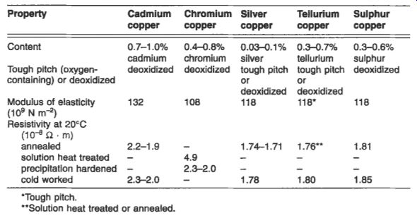
Table 8 Selected physical properties of copper alloys
Chrome copper is particularly suitable for high-strength applications such as spot and seam types of welding electrodes. Strip and, to a lesser extent, wire are used for light springs which carry current. In its heat-treated state, the material can be used at temperatures up to 350°C without risk of deterioration of properties, and it is used for commutator segments in rotating machines where the temperatures are higher than normal. In the solution heat-treated condition, chromium copper is soft and can be machined; in the hardened state it is not difficult to cut but it is not free-machining like leaded brass or tellurium copper. Joining methods similar to cadmium copper are applicable, and chromium copper can be welded using gas-shielded arcs.
Silver copper has the same electrical conductivity as ordinary high-conductivity copper, but its softening temperature, after hardening by cold work, is much higher and its resistance to creep at moderately elevated temperatures is enhanced. Because its outstanding properties are in the work-hardened state it is rarely required in the annealed condition. Its principal uses are in electrical machines which operate at high temperatures or are exposed to high temperatures in manufacture. Examples of the latter are soft soldering or stoving of insulating materials. Silver copper is available in hard-drawn or rolled rods and sections, especially those designed for commutator segments, rotor bars and similar applications. Silver copper can be soft soldered, silver soldered, brazed or welded without difficulty but the temperatures involved in all these processes are sufficient to anneal the material if in the cold-worked condition.
Because the tough pitch material contains oxygen as dispersed particles of cuprous oxide, it is also important to avoid heating it to brazing and welding temperatures in a reducing atmosphere. In the work-hardened state silver copper is not free-cutting, but it is not difficult to machine.
Telliirium copper offers free-machining, high electrical conductivity, retention of work hardening at moderately elevated temperatures and good corrosion resistance.
It is unsuitable for most types of welding, but gas-shielded arc welding and resistance welding can be effected with care. A typical application is magnetron bodies, which are often machined from solid. Tellurium copper can be soft soldered, silver soldered and brazed without difficulty. For tough pitch, brazing should be done in an inert or slightly oxidizing atmosphere since reducing atmospheres are conducive to embrittlement. Deoxidized tellurium copper is not subject to embrittlement.
Sulphur copper- is free-machining and does not have the tendency of tellurium copper to form coarse stringers in the structure which can affect accuracy and finish. It has greater resistance to softening than high-conductivity copper at moderately high temperatures and gives good corrosion resistance. Sulphur copper has applications in all machined parts requiring high electrical conductivity, such as contacts and connectors; its joining characteristics are similar to those of tellurium copper. It is deoxidized with a controlled amount of phosphorus and therefore does not suffer from hydrogen embrittlement in normal torch brazing, but long exposure to a reducing atmosphere can result in loss of sulphur and consequent embrittlement.
4.1.2 Aluminum and its alloys
For many years aluminum has been used as a conductor in most branches of electrical engineering. Several aluminum alloys are also good conductors, combining strength with acceptable conductivity. Aluminum is less dense and cheaper than copper, and its price is not subject to the same wide fluctuations as copper. World production of aluminum has steadily increased over recent years to overtake that of copper, which it has replaced in many electrical applications.
There are two specifications for aluminum, one for pure metal grade ZE and the other for a heat-treatable alloy 91E. Grade 1E is available in a number of forms which are extruded tube (ElE), solid conductor (ClE), wire (GlE) and rolled strip (D 1E). The heat-treatable alloy, which has moderate strength and a conductivity approaching that of aluminum, is available in tubes and sections (E91E). The main application areas are: Busburs. Although aluminum has been used as busbars for many years, only recently has it been accepted generally. The electricity supply industry has now adopted aluminum busbars as standard in 400 kV substations, and they are also used widely in switchgear, plating shops, rising mains and in the UK aluminum smelting plants.
Sometimes the busbars are tin-plated in applications where joints have to be opened and remade frequently.
Cable. The use of aluminum in wires and cables is described at length in Section
9. Aluminum is used extensively in cables rated up to 11 kV and house wiring cable above 2.5 mm2 is also available with aluminum conductor.
Overhead lines. The Aluminum Conductor Steel Reinforced (ACSR) conductor referred to in section 14.3 and Fig. 14.3 is the standard adopted throughout the world, although in the USA Aluminum Conductor
Aluminum alloy wire Reinforced (ACAR) is rapidly gaining acceptance; it offers freedom from bimetallic corrosion and improved conductance for a given cross-section.
Motors. The use of aluminum in cage rotors of induction motors is described in Section 10. Motor frames are often die-cast or extruded from aluminum, and shaft- driven cooling fans are sometimes of cast aluminum.
Foil windings are suitable for transformers, reactors and solenoids. They offer a better space factor than a wire-wound copper coil, the aluminum conductor occupying about 90 per cent of the space, compared to 60 per cent occupied by copper. Heat transfer is aided by the improved space factor and the reduced insulation that is needed in foil windings, and efficient radial heat transfer ensures an even temperature gradient. Windings of transformers are described in more depth in section 6.2.2.
Hearing elements have been developed in aluminum but they are not widely used at present. Applications include foil film wallpaper, curing concrete and possibly soil warming.
Heat sinks are an ideal application for aluminum because of its high thermal conductivity and the ease of extrusion or casting into solid or hollow shapes with integral fins. They are used in a variety of applications such as semiconductor devices and transformer tanks. The low weight of aluminum heat sinks make them ideal for pole-mounted transformers and there is the added advantage that the material does not react with transformer oil to form a sludge.
4. f. 3 Resistance alloys
Many alloys with high resistivity have been developed, the two main applications being resistors and heating elements.
Alloys for standard resistors are required to have a low temperature coefficient of resistivity in the region of room temperature. The traditionally used alloy is Manganin, but this has increasingly been replaced by Ni-Cr-A1 alloys with the trade names Karma and Evanohm. The resistivity of these alloys is about 1.3 pa m and the temperature coefficient is k 0.5 x 10^-5/0C. For lower-precision applications copper- nickel alloys are used, but these have a lower resistivity and a relatively high thermo emf against copper.
For heating elements in electric fires, storage heaters and industrial and laboratory furnaces there is a considerable range of alloys available. A considerable resistivity is required from the alloy in order to limit the bulk of wire required, and the temperature coefficient of resistivity must be small so that the current remains reasonably constant with a constant applied voltage. Ni-Cr alloys are used for temperatures up to 1 100°C, and Cr-Fe-Al alloys are used up to 1400°C. Ceramic rods are used for higher temperatures and silicon carbide may be used up to 1600°C. For even higher temperatures, the cermets MoSiz and Zircothal are used. The maximum temperatures at which the materials may be used depend on the type of atmosphere.
4.2 Semiconductors
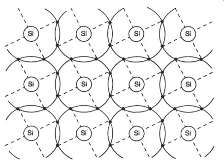
Fig. 8 Atoms in a silicon crystal
A semiconductor is able at room temperature to conduct electricity more readily than an insulator but less readily than a conductor. At low temperatures, pure semiconductors behave like insulators. When the temperature of a semiconductor is increased, or when it is illuminated, electrons are energized and these become conduction electrons.
Deficiencies or 'holes' are left behind: these are said to be camera of positive electricity.
The resulting conduction is called intrinsic conduction.
The common semiconductors include elements such as silicon, germanium and selenium and compounds such as indium arsenide and gallium antimonide. Germanium was originally used for the manufacture of semiconductor devices, but because of resistivity problems and difficulty of supply it was replaced by silicon which is now the dominant material for production of all active devices such as diodes, bipolar transistors, MOSFETs, thyristors and IGBTs.
Both silicon and germanium are group IV elements of the periodic table, having four electrons in their outer orbit. This results in a diamond-type crystal giving a tight bond of the electrons. Figure 3.8 shows the atoms in a silicon crystal. Each atom is surrounded by eight electrons, four its own and four from neighboring atoms; this is the maximum number in an orbit and it results in a strong equilibrium. It is for this reason that pure crystals of silicon and germanium are not good conductors at low temperature.
4.2.1 Impurity effects and doping
The conductivity of group IV semiconductors like silicon can be greatly increased by the addition of small amounts of elements from group V (such as phosphorus, arsenic or tin) or group 111 (such as boron, aluminum, gallium or indium). Phosphorus has five electrons in its outer shell and when an atom of phosphorus replaces an atom of silicon it generates a free electron, as shown in Fig. 9. This is called doping. The extra electrons are very mobile; when a voltage is applied they move very easily and a current passes. If 10l6 phosphorus atoms/cm3 are added to a pure crystal, the electron concentration is greatly increased and the conductivity is increased by a factor of about a million. The impurities are called donor atoms and the material is an impurity semiconductor. This is called an n-type semiconductor, and n represents the excess of free electron carriers.
If the material is doped with group III atoms such as indium, then a similar effect occurs. This is shown in Fig. 10. The missing electron forms a 'hole' in the structure which acts as a positive carrier. This structure is known as a p-type semiconductor -- and p represents the excess of positive carriers. The impurities are called acceptor atoms.
A single crystal containing both n-type and p-type regions can be prepared by introducing the donor and acceptor impurities into molten silicon at different stages of the crystal formation. The resultant crystal has two distinct regions of p-type and n-type material, and the boundary joining the two areas is known as a p-n junction.
Such a junction may also be produced by placing a piece of donor impurity material against the surface of a p-type crystal or a piece of acceptor impurity material against an n-type crystal, and applying heat to diffuse the impurity atoms through the outer layer. When an external voltage is applied, the n-p junction acts as a rectifier, permitting current to flow in only one direction. If the p-type region is connected to the positive terminal of a battery and the n-type to the negative terminal. a large current flows through the material across the junction, but when the battery is connected in the opposite manner, no current flows. This characteristic is shown in Fig. 11.
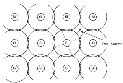
Fig. 9 Representation of an n-type semiconductor Fig. 10 Representation
of a p-type semiconductor
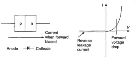
Fig. 11 Construction, symbol and characteristic of a semiconductor diode
4.2.2 The transistor
Many types of device can be built with quite elaborate combinations and constructions based around the n-p and pn junction. Further information on these devices may be found in reference 3F. Possibly the most important single device is the transistor, in which a combination of two or more junctions may be used to achieve amplification. One type, known as the n-p-n junction transistor, consists of a very thin layer of p-type material between two sections of n-type material, arranged in a circuit shown in Fig. 12. The n-type material at the left of the diagram is the emitter element of the transistor, constituting the electron source. To permit the flow of current across the n-p junction, the emitter has a small negative voltage with respect to the p-type layer, or base component, that controls the electron flow. The n-type material in the output circuit serves as the collector element, which has a large positive voltage with respect to the base in order to prevent reverse current flow. Electrons moving from the emitter enter the base, are attracted to the positively charged collector, and flow through the output circuit. The input impedance between the collector and base is low, whereas the output impedance between collector and base is high. Therefore, small changes in the voltage of the base cause large changes in the voltage drop across the collector resistance, making this type of transistor an effective amplifier.
Similar in operation to the n-p-n type is the p-n-p junction transistor also shown in Fig. 12. This also has two junctions and is equivalent to a triode vacuum tube.
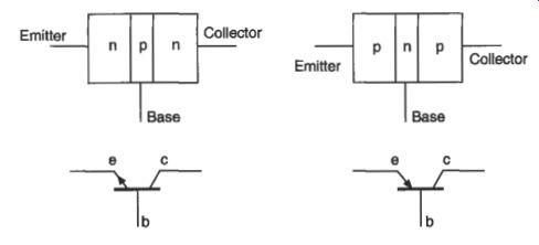
Fig. 12 Construction and symbols for n-p-n and p-n-p transistors
Other types, such as the n-pn-p junction transistor, provide greater amplification than these two-junction transistors.
4.2.3 Printed circuits and integrated circuits
A printed circuit is an electrical circuit made by printing and bonding conducting material as a network of fine threads on a thin ceramic or polymer insulating sheet.
This replaces the wiring used in conventional circuits. Other elements such as transistors, resistors and capacitors can be deposited onto the same base as the printed circuit.
An integrated circuit is effectively a combination of many printed circuits. It is formed as a single unit by diffusing impurities into single-crystal silicon, which then serves as a semiconductor material, or by etching the silicon by means of electron beams. Several hundred Integrated Circuits (ICs) are made at a time on a thin wafer several centimeters in diameter, and the wafer is subsequently sliced into individual ICs called chips.
In large-scale integration (LSI), several thousand circuit elements such as resistors and transistors are combined in a 5 mm square area of silicon no more than 0.5 mm thick. Over 200 such circuits can be arrayed on a silicon wafer 100 mm in diameter.
In very large-scale integration (VLSI), hundreds of thousands of circuit elements fit onto a single silicon chip. Individual circuit elements on a chip are interconnected by thin metal or semiconductor films which are insulated from the rest of the circuit by thin dielectric layers. This is achieved by the formation of a silicon dioxide layer on the silicon wafer surface, silicon dioxide being an excellent dielectric. Metal oxide semi-conductor field effect transistors (MOSFETs) are made using this technique.
These transistors are used for high-frequency switching applications and for random access memories in computers. They have very high speed and low power consumption.
4.2.4 The microprocessor
The microprocessor is a single chip of silicon which has the ability to control processes.
It can form the central processing unit (CPU) of a small computer and it can be used in a wide range of other applications. A microprocessor may incorporate from a thousand up to several hundred thousand elements. It typically contains a read-only memory (ROM), that is a memory that can be read repeatedly but cannot be changed, but it may also have some random-access memory (RAM) for holding transient data.
Also present in a microprocessor are registers for holding computing instructions, for holding the 'address' of each instruction in turn and for holding data, and a logic unit.
Interfaces for connecting with external memories and other systems are included as required.
The microprocessors used in personal computers (PCs) have been the subject of intensive development during the last decade. The speed of operation is usually defined as a frequency and chips with frequencies of 667 MHz or higher are now available; this corresponds to an individual operation time of 1.5 nanoseconds. The amount of information that can be transferred in parallel and held in registers is known as a bit, and 64-bit processors are now available.
4.3 Superconductors
The ideal superconducting state is characterized by two fundamental properties, which are the disappearance of resistance when the temperature is reduced to a critical value, and the expulsion of any magnetic flux in the material when the critical temperature (T,) is reached. Superconductivity was first discovered in mercury in 1911. Other elements have subsequently been found to exhibit superconductivity and theories have been developed to explain the phenomenon. The critical temperatures for these materials were typically about 10K (-263°C) which meant that they had to be cooled with liquid helium at 4K. In general these materials have been of academic interest only because they could only support a low current density in a low magnetic field without losing their superconducting properties.
In the 1950s a new class of materials was discovered. These are metallic alloys, the most important being niobium titanium and niobium tin. The highest critical temperatures achieved by these materials is 23.2K and they can be used to produce magnetic flux densities of over 15 T. The main commercial application for these low- T, superconductors is for magnets in medical imaging equipment which requires the high fields to excite magnetic resonance in nuclei of hydrogen and other elements.
The magnet or solenoid of the magnetic resonance imaging (MRI) unit has an internal diameter of about 1.2 m and the patient to be examined is put into this aperture. The image from the resonance test shows unexpected concentrations of fluids or tissue and enables a diagnosis. Superconducting magnets producing high magnetic fields are also used in magnetic research and in high-energy physics research; other applications such as dc motors and generators, levitated trains, cables and ac switches have been explored but the complexity and high cost of providing liquid helium has prevented commercial development.
In late 1986 a ceramic material LaBaCuO was discovered to be superconducting at 35K and in 1987 the material Yl3aCuO was found to have a critical temperature of 92K. Since that time the critical temperatures of new materials has progressively increased to over 130K. Examples of these are BiSrCaCuO (with a T, of 106K), ThBaCaCuO (T, of 125K) and HgBaCaCuO (T, of 133K). The enormous significance of these discoveries is that the materials will be superconducting in liquid nitrogen, which has a boiling point of 77K and is much easier and cheaper to provide than helium.
The consequence of these high-temperature superconductors has been an unprecedented upsurge of research activity throughout the world. Much of this work is directed towards finding materials with even higher T, values and towards establishing viable production methods. These new materials are brittle and unless they are in the form of very thin films they will only operate up to current densities of about 0.1-1 Nm^2. The indications are, however, that they will operate in flux densities exceeding 50 T. Attention is now being turned to applications for the materials which are available.
Their brittleness rules out their direct use as conventional wires in magnets or cables, although a prototype cable carrying 2300 A over 1 m has been made. In this case the superconducting ceramic oxide was deposited onto flexible tape, and this technique leads to the possible use of cable for winding solenoids to produce high magnetic fields. Other applications which are already in use are superconducting quantum interference device (SQUID) magnetometers which are used for detecting very small currents in the human body to detect and pinpoint defects. The materials are also in use in transmission aerials, in which low noise at low temperatures is an advantage.
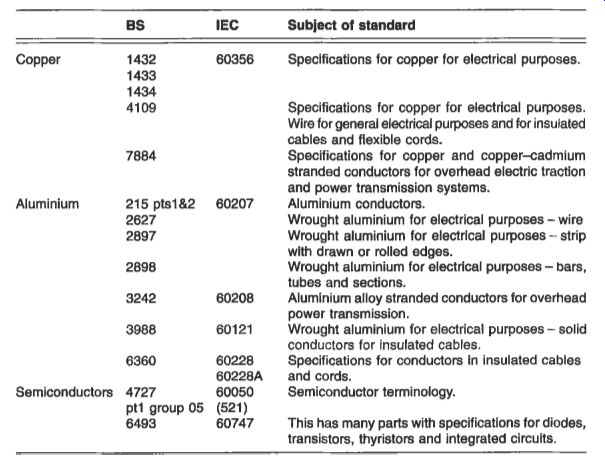
Table 9 Standards for conducting materials
5. Standards
Each country has in the past had its own standards for materials. Over the past 20 years or so there has been a movement towards international standards which for electrical materials are produced by IEC (International Electrotechnical Commission). When an IEC standard is produced the member countries copy this standard and issue it under their own covers. This now applies to BSI, ASTM, DIN and the French standards organization. Where appropriate, standards are also issued as applying to all the European Union.
Leading standards for electrical materials are shown in Table 9.