AMAZON multi-meters discounts AMAZON oscilloscope discounts
1. Introduction
Much of industry depends on heat processes to refine, shape, modify, dry, bake or carry out any one of a number of operations. Traditionally, much of this heat has been provided by fossil fuel; in earlier days this was coal and its derivatives and more recently it has been oil and gas. Electricity was used to provide drives for machinery and auxiliaries such as blowers, or for very specialized applications. The large-scale use of electricity was limited to such processes as electrochemical extraction of the chemicals originating from salt, or the extraction of aluminum from bauxite. In part, the explanation for the limited use of electroheat has been an economic one, and in some areas this continues to be the case. At the point of delivery, electricity in most countries is much more expensive than fossil fuels. This is inevitable because most electricity has been generated using fossil fuel, with a conversion efficiency that cannot be better than that of the Carnot cycle. Furthermore, the equipment necessary for the generation and distribution of electricity requires very significant capital investment. As a result, the case for the use of electricity in process heating needs to take into account other aspects of manufacturing costs and process benefits, such as improvements in product quality, reduced manning levels and increased throughput for a given capital investment.
Nevertheless, electroheat technologies are now widely established in processing and manufacturing industries ranging from metals, glass and ceramics to textiles, paper, food and drink. The heating techniques use frequencies which cover a significant part of the electromagnetic spectrum, from dc to terahertz, and at powers which range from a few watts to many megawatts. The different processes which have been developed, and the frequency and power ranges which they use, are summarized in Table 1.
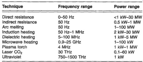
Table 1 Electric heating processes
The relative importance of the different techniques has changed as industry moves away from heavy engineering operations. In particular, some electroheat processes related to the iron and steel industry have decreased in relative importance whilst others, aimed at materials with higher added value, are becoming more widely accepted.
It is also apparent that even in the heavy industries such as metals and ceramics, certain traditional and novel electroheat techniques are of great importance since they bring with them better process control, leading to higher product quality and reduced manufacturing costs. Further details of most of these processes can be found in reference 13A. It is possible to categorize electroheat techniques in a variety of ways. The following are examples:
by the part of the frequency spectrum in which they operate, for example infrared, microwave or ultraviolet
by the material being processed, such as metal melting or metal heat treatment
by the generic name of the process, such as induction heating, dielectric heating or laser
No single categorization is generally accepted and a mixture of these is adopted in the structure of this Section. Metal melting by various methods is dealt with in section 2. The route to a final component may also involve heat treatment, either for size reduction, to modify properties or to work into final form. A number of electroheat techniques are used and these are grouped under direct resistance heating, in section 3, and indirect resistance heating, in section 4. The later sections deal with more recently accepted technologies.
2. Metal melting
Electroheat is used in a number of ways in the metals industry, from the initial refining through to the formation into finished shape. In the case of refining, perhaps the greatest use is for the extraction of aluminum from bauxite. Because this is a very energy-intensive process, it is normally carried out in places where cheap hydroelectric power is available, such as Canada. There are relatively few installations in Europe.
Metal melting may take place for secondary refining, for recycling of scrap or for the production of castings. It is normally considered separately from metal heating for hot working, because the implementation of the methods for liquid metals is usually quite different.
The electroheat furnaces which are established for the melting of metals include arc, electron beam and coreless induction furnaces. The choice is usually based on the demand schedule for liquid metal which is required by the casting process. The requirements of a small foundry producing a few specialist castings each day are quite different from those of a large automated foundry. The seven main types of furnaces commonly used in the melting of metals are described in the following sections.
2.1 The arc furnace
This is mainly used for the production of liquid steel by the melting of scrap. It consists of a squat, refractory-lined cylindrical vessel with a movable domed refractory roof, as shown in Fig. 1. The roof is swung open to allow the furnace to be charged with scrap metal, and is closed prior to the start of the melting process. The three graphite electrodes pass through holes in the roof, and each is supplied through flexible cables and bus tubes from one of the three phases of a transformer. The metal charge forms the star point of the three-phase load circuit.
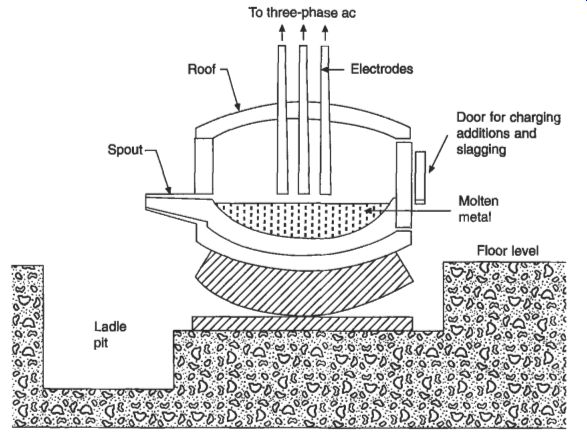
Fig. 1 Arc furnace
A variant of this conventional scrap melter is the vacuum arc furnace, which is used for the refining of metals. A partial vacuum is maintained in the vessel to minimize oxidation during melting.
The substation for a large arc furnace is normally adjacent to the furnace itself, and it contains the furnace transformer, which normally has a star-connected primary and (in the UK) an input voltage of 33 kV. The transformer must withstand the very large electromechanical forces which are produced by the high short-circuit currents.
It is oil cooled and the power is varied using on-load tapchangers. Further comments on this class of transformer can be found in section 6.3.10.
As an electrical load, the arc furnace is less than ideal. The current can vary from zero, when the arc is extinguished at current zero, to a short-circuit level when scrap contacts the electrodes. The physical movement of the pieces of solid charge and of the melt causes variation in the arc length which can fluctuate many times within a second. In addition, the arc length varies due to mechanical vibration of the electrode and its supporting structure. These effects combine to prevent a constant power level being delivered by each of the phases, and this results in a number of problems which affect the performance of the furnace, the local electricity supply and the acoustic noise level.
2.2 The submerged arc process
This is not essentially an arc process, since heating occurs mainly by direct resistance effects, with perhaps some limited heating from arcs and sparks during interruption of the current path. The general arrangement is shown in Fig. 2.
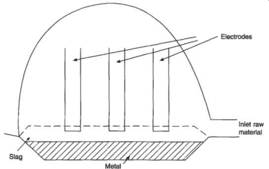
Fig. 2 Submerged arc furnace
The principal application is in the reduction of ferroalloys such as ferromanganese, nickel, chrome, silicon, tungsten and molybdenum, which have a high melting point.
These metals are subsequently re-melted in an arc furnace to produce special alloys.
Fused oxides may also be produced by the submerged arc process.
2.3 Electroslag refining
This is an alternative to vacuum arc processes for materials which are not unduly reactive in air. A high degree of refining can be obtained, since the droplets of molten metal penetrate the molten slags, enabling de-sulphurization to be carried out and oxide inclusions to be removed. As in the vacuum arc furnace, a molten pool is formed on the solidifying ingot, and there are similar advantages.
The general arrangement of an electroslag refining furnace is shown in Fig. 3.
The current path vanes according to the construction of the furnace and varies with the state of the melt. In general terms, current passes from the electrodes, through the slag and from the slag to the baseplate, through the vessel walls or the ingot, or both.
2.4 The electron-beam furnace
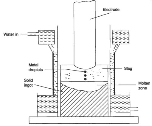
Fig. 3 Electroslag refining furnace
Electron beams can be used for melting, as well as for welding and the production of evaporated coatings. The beam is obtained from a heated filament or plate, and is accelerated in an electron gun by a high electric field which is produced by one or more annular electrodes. Electrons on the axis of the gun pass through the final anode at very high speeds, typically 85 x 10^6 m/s at 20 kV. The electron gun and chamber are kept at a low pressure of around 0.001 Pa. Since little energy is lost from scatter or from the production of secondary electrons, practically all of the kinetic energy of the beam is converted into heat at the workpiece. The conversion from electrical energy input to thermal energy in the workpiece is therefore very high.
The electron-beam furnace is shown diagrammatically in Fig. 4. It utilizes a cooled ingot mold in the same way as the vacuum and electroslag furnaces.
2.5 The coreless induction furnace
This consists of a refractory crucible encircled by a solenoid coil which is excited from a single-phase ac supply. A diagrammatic view is shown in Fig. 5.
The fluctuating axial magnetic field links the charge within the crucible and causes Z2R heating in the charge. The power induced in the charge and the efficiency of the furnace can be calculated according to the equations given later in section 13.6. using appropriate material property values. Depending upon the resistivity of the material in the charge, the coreless furnace converts the electrical input power to heat in the charge with an efficiency of 65-80 percent. This efficiency is largely independent of frequency, but is improved by the high charge permeability found in ferromagnetic materials such as steel scrap.
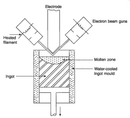
Fig. 4 Electron-beam melting furnace.
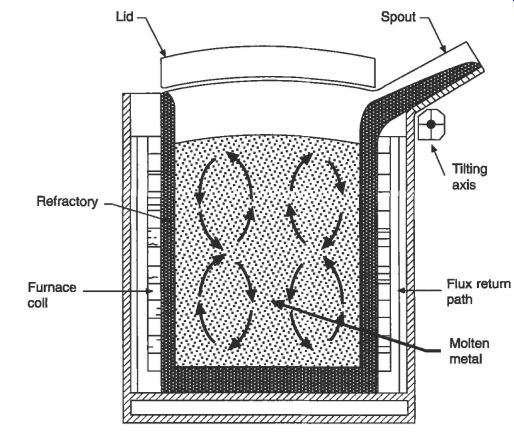
Fig. 5 Diagrammatic view of a coreless induction furnace.
2.6 The channel induction furnace
During the 1970s the channel furnace became accepted as a melting unit for cast iron, and largely replaced the coke-fired cupola. Its acceptance was due mainly to improved refractory technology, which allowed useful levels of power to be applied.
Until that time the furnace had mainly found application in iron foundries as a holding unit, in which previously melted liquid metal is maintained at a temperature suitable for pouring into the casting molds.
In the channel induction furnace, a mains-frequency solenoid coil encircles one leg of a lamination pack, and the resultant alternating magnetic field induces joule heating in a loop of molten metal surrounding the coil, this metal loop acting as a single-turn secondary of the transformer. The arrangement is illustrated in Fig. 6.
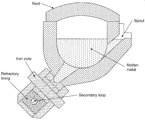
Fig. 6 Diagrammatic view of a channel induction furnace
The close coupling between the induction coil and the metal loop results in a higher power factor than is achieved with the coreless induction coil, and the efficiency of converting electrical power into heat is therefore also higher, being typically above 95 percent. The molten metal loop must be continuous, and it is not allowed to solidify while energized in case the continuity is broken during contraction.
The use of channel furnaces for aluminum melting has been constrained by problems of oxide build-up in the metal loop. This necessitates special designs to allow easy cleaning. For bulk melting applications, European furnace companies and researchers have in recent years produced high-power designs of up to 1.3 MW per inductor, with freedom from loop blockage. This enables the high efficiency of this type of furnace to minimize melting costs.
2.7 The resistance furnace
Electric radiant heating techniques for metal melting are most widely used in the zinc and aluminum foundry sectors. There is much less use in the copper base alloy market which requires higher melting temperatures. In general, resistance heating is used where induction furnaces are not suited to the metal demand patterns. In the case of aluminum the application of resistance heating ranges from crucible bale-out furnaces of 25 kg capacity, where metal is scooped out of the container as required for pouring into molds, to well-insulated box-like receivers of over 10 tomes capacity.
Crucible furnace designs comprise a steel shell which contains insulating material, heating elements and a carbon-based crucible which is located in the central chamber.
The general arrangement is shown in Fig. 7. The highest outputs are around 120 kW, which gives a maximum melting rate for aluminum of 230 kg/hour in a 600 kg capacity furnace. This can be compared with a coreless induction furnace of similar capacity which, with its higher power density, can achieve melting rates about three times greater.
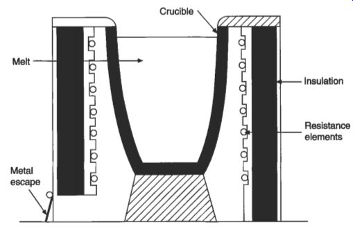
Fig. 7 Diagrammatic view of a resistance crucible furnace.
Crucible furnaces exist in both tilting and bale-out configurations, and great strides have been made to improve performance figures in the light of competition between manufacturers and from other fuels. As an example, a typical 180 kg bale-out furnace has a holding requirement of about 4 kW, with advantages of automatic start-up, good working environment and close temperature control. Typically, the metal content is about eight times the optimum melt rate achieved when these large structures have reached thermal equilibrium.
An alternative high-efficiency heating mode for metals with a low melting point is provided by immersion heating, using silicon carbide or wire elements in silicon carbide-based tubes.
3. Heat treatment by direct resistance heating
This is used in the iron and steel industry for heating rods, wire and billets prior to rolling, forging or other hot working. It is also used for annealing of ferrous and non- ferrous materials. The process works through direct contact with the material, and a schematic of the general arrangement is shown in Fig. 8.
Direct resistance heating is also used for melting glass, in electrode boilers for water heating or steam raising, and in salt baths for the surface heat treatment of metallic components. In these applications it may be used alone or in combination with other fuels.
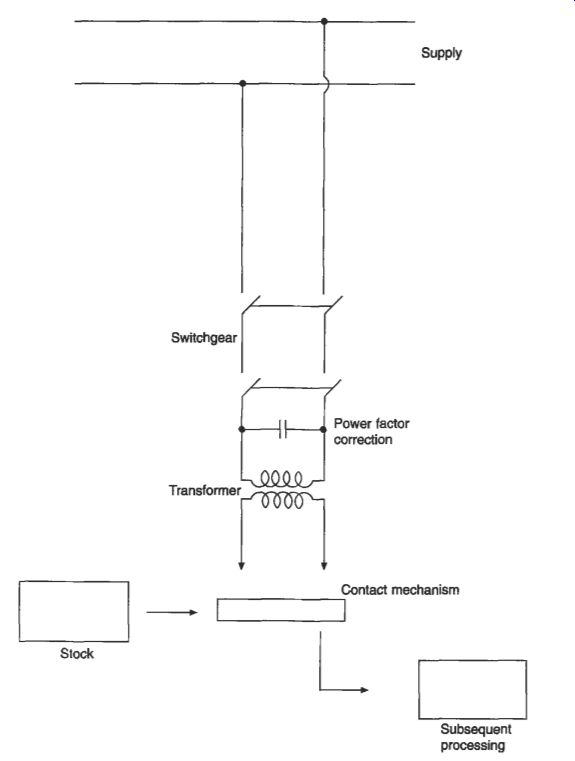
Fig. 8 Direct resistance heating
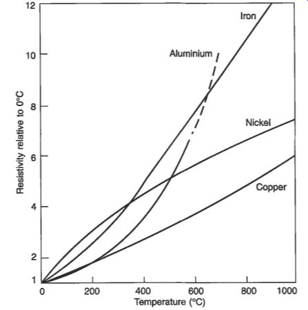
Fig. 9 Variation of resistivity with temperature for aluminum, copper,
nickel and iron
Table 2 Electrical resistivity of typical metals
3.1 Metals
The resistivity of several common metals is shown in Table 13.2, and the variation of some of these resistivities with temperature is illustrated in Fig. 9.
Because of its relatively high resistivity, steel can be heated efficiently in billets of up to 200 mm^2 section, provided that the length of the billet is several times greater than its diameter. Heating time is from seconds to a few minutes, so heat losses (for instance radiation from the surface and thermal conduction through the contacts) are small. The efficiency of the process can be 90 percent or better. The workpiece resistance is low, and for these high efficiencies to be achieved the supply resistance must be much lower.
For copper and other low-resistivity metals, the length-to-diameter ratio of the billet should be considerably greater than 6 if the process is to be successful, and consequently it is usually applied to the annealing of wire and strip.
In all cases the cross-sectional area of the current path must be uniform, otherwise excessive heating will occur at the narrower sections, with the possibility of melting.
In billets of larger cross-section, a non-uniform current density can arise as a result of skin effect. This leads to higher heating rates at the surface, but these are counteracted by increased heat loss at the surface.
The direct resistance heating of bar and billets is a single-phase load that is switched at frequent intervals. This results in transient voltage disturbances and in voltage unbalance at the point of common coupling. The load can be phase balanced by inductive and capacitive components, and in large units the switch-on disturbances may be compensated by a soft-start arrangement.
3.2 Glass
At temperatures above 1100°C, glass has a low viscosity and a resistivity which is low enough for direct resistance heating to be considered at acceptable voltages. The variation of the resistivity of glass with temperature is shown in Fig. 10. In the UK, electricity is used in mixed melting units where electrodes are typically added to a fuel-fired furnace to increase the output for a relatively low additional capital investment.
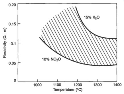
Fig. 10 Variation of resistivity with temperature of glasses
Current is passed between electrodes which are immersed in the molten glass. The electrodes must withstand the high temperatures and forces which arise from the movement of molten glass across their surface. It is also necessary to protect the electrodes from exposure to the atmosphere. Molybdenum or tin oxide electrodes are used in order to avoid contamination of the glass by pick-up of electrode material, and the current densities are of the order of 1500 Nm^2. Single-, two- or three-phase electrode systems may be employed. Scott-connected transformers (as described in section 6.2.3) are used for the two-phase connection. The three-phase arrangement produces electromagnetic forces in the glass which, together with the thermal forces, lead to a significant movement in the melt; this improves quality and melt rate provided it is not excessive. Three phase is also preferred for phase balance and low cost.
Existing electric furnaces have usually followed a traditional design pattern with a rectangular tank, but circular designs have now been adopted and it is claimed that these give improved stirring in the melting zone.
The power input to the furnace, and hence the melting rate, is controlled by varying the input voltage with tapped transformers or saturable reactors: an alternative method is to change the effective surface area of the electrodes by raising them from the melt.
3.3 Salt baths
These can be used for the heat treatment of metal components. The heated salt reacts chemically with the surface layer of the workpiece to give the required surface properties. At temperatures above about 800 C, direct resistance heating is the only practical method.
Although the salt is a good conductor when molten, the bath must be started up from cold by using an auxiliary starting electrode to draw a localized arc. The electrodes have to withstand the corrosive effects of the salt, and are manufactured from graphite or a corrosion-resistant steel alloy. Currents of up to 3 kA at 30 V are required, and both single-phase and three-phase units are available.
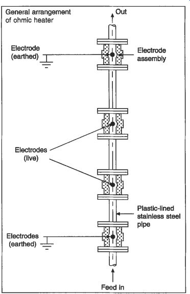
Fig. 11 Direct resistance heating for pumpable fluids
3.4 Foods and other fluids
In recent years the principles of direct resistance heating have been applied to a range of other pumpable fluids, typically food and aggressive liquids such as zinc phosphate.
The equipment in these applications consists of a pipeline interspaced with four electrodes which are each built into an insulated housing and connected to a three- phase supply in delta. The general arrangement is shown in Fig. 11. The pipeline itself is made from stainless steel and is insulated internally by a polymeric coating to ensure that the current flows through the fluid itself.
In the food industry the technique is known as 'ohmic heating'. Equipment rated up to 100 kW and 3.3 kV has been used in this industry to heat up to 120°C liquids and pastes which often contain solid particulates with characteristic dimensions up to 25 mm. This results in the cooking and sterilizing of the food in a single, very rapid operation of a few tens of seconds. When linked into an aseptic packaging line it gives an almost indefinite shelf life in ambient temperature storage.
4. Indirect resistance heating
In this method, electricity is passed through a suitable conducting material which forms a heating element, and heat is transferred to the workpiece or the medium to be heated by conduction, convection or radiation, or a combination of these. The element is the hottest component of the system, and the factors which determine the choice of element materials will depend on the nature of the heat transfer process as well as the physical and chemical characteristics of the process environment.
Infrared heating falls under the generic heading of indirect resistance heating, but for clarity it is covered separately in section 5.
4.1 Metallic elements
Metallic elements traditionally take the form of wire, strip or tape. For a given operating temperature, the shortest operating life tends to be found with the lowest cross-section of wire or tape, because failure occurs through progressive oxidation of the surface and the consequent reduction in mechanical strength.
The choice of metal composition for the element will depend upon the required operating temperature, the material resistivity, the temperature coefficient of resistance, corrosion resistance at high temperature, mechanical strength, formability and cost.
Many metals and alloys are used, but the most common for industrial applications are based on nickel-chromium, iron-nickel-chromium or iron-chromium-aluminum alloys.
4.2 Sheathed elements
The elements may be protected from the working environment by an insulation layer and an outer sheath.
In the heating elements of many domestic appliances (such as cooker rings, immersion heaters and kettle elements) a purified magnesium oxide powder separates the helical element coil from a sheath which may be of copper, stainless steel or a nickel-base alloy. These elements are often rated in watts per square centimeter of sheath.
Such mineral-insulated elements are also used in cartridge heaters, radiant panels and immersion heaters for industrial applications. Also available are thin-strip or band heaters, which have mica insulation between the element and the sheath.
4.3 Ceramic elements
A range of ceramic materials exist which have a sufficiently high electrical conductivity to act as element material. These materials include silicon carbide, molybdenum disilicide, lanthanum chromite and hot zirconia. Graphite is another recognized non- metallic element material, but this can only be used in inert atmospheres such as steam and carbon dioxide.
Ceramic elements usually have a hot zone which is created by a thin section or a spiral cut; this hot zone is supported by two or more cold ends which are of a thicker section or have been impregnated with a metallic phase to lower the resistance locally.
4.4 Electric ovens and furnaces
These are used for a great variety of purposes, ranging from sintering ceramic materials at temperatures up to 1800°C to drying processes which are close to ambient temperature.
Power ratings may be from a few kilowatts up to more than a megawatt. An oven usually has an upper temperature limit of about 450°C. and a furnace is usually used for higher temperature processes. Most modem ovens and furnaces incorporate lightweight insulation with low thermal conductivity to reduce thermal inertia and surface losses.
Metal resistance-heating elements for furnaces are usually in the form of wire, strip or tube. Elements for low voltage and high current have a heavy-section construction in an alloy casting or with corrugated or welded tube. Helically wound wire heating elements are made with a mandrel-to-wire diameter ratio of between 3 : 1 and 8 : 1. This ratio is limited by the tendency of the helical winding to collapse under its own weight at high operating temperatures. Coiled-wire or strip elements may be inserted in ledges or grooves, supported at intervals by pegs of nickel alloy or ceramic. The end connections of the elements are normally of a different material in order to reduce attack from oxidation and chemical reaction with the re-fractories, and they have a lower resistance in order to reduce the heat dissipation where the leads pass through the furnace wall.
Ovens may use natural or forced convection, and are widely employed in a range of applications including curing, baking, the annealing of glass and aluminum, and the drying and preheating of plastics prior to forming. Coiled nickel-chrome wire or mineral-insulated metal-sheathed elements are distributed around the oven in order to obtain a uniform temperature distribution. The heat transfer rate may be increased by using a fan to circulate air over the heating elements and onto the workpiece, the air being recirculated through ducts. An important advantage of convective ovens is that the operating temperature is normally the element temperature, and the maximum temperature is never exceeded since the process is self-limiting. This prevents overheating if the material is left in the oven too long, and it is particularly important for temperature-sensitive materials such as plastics.
High heating rates can be achieved by direct radiation from heating elements in infrared ovens. Here the oven walls are made of sheet metal which reflects or re-emits the radiation. Infrared processes are usually associated with surface heating which is applied, for example, to paint and other coatings. The efficiency in these applications may be very high in comparison with other methods which also heat the substrate.
Fig. 12 Bell furnace
Forced-convection furnaces allow high heating rates and with careful design good temperature uniformity can be achieved, but they are normally limited to a maximum temperature of 700-900°C. Higher operating temperatures can be achieved with the pit furnace, in which radiation is the dominant mode of heat transfer and, by using a retort, the process can be carried out in a controlled atmosphere.
The bell furnace may be used as a hot-retort vacuum furnace. The layout of a bell furnace is shown in Fig. 12. By reducing the pressure inside the bell retort, oxidation of the product is minimized. Since heat losses by convection are greatly reduced at low pressure, the bell can be raised when the required temperature is reached, and one bell may be used to heat several retorts.
Further information on furnace types and rating methods is available in reference 13A.
5. Infrared heating
Infrared is one of the most widely used electrical process heating techniques in industry, finding application in all sectors. Using electromagnetic energy as a source, it provides the potential for high input power densities and non-contact heating.
The peak wavelength of an infrared source depends upon its temperature. As the temperature is increased, the peak wavelength is shorter, proportionately more of the power is radiated at shorter wavelengths and the power densities are higher. This effect is illustrated in Fig. 13.
Typical input power densities for different types of infrared sources are given in Table 3.
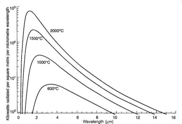
Fig. 13 Black-body radiation characteristics
Table 3 Characteristics of infrared heaters
Lower-temperature infrared sources (long and medium wave) are normally used for surface heating applications such as the drying of coatings, curing of paints and powder finishes, reflow soldering and browning of foods. Short-wave heaters are used where higher product temperatures are required (for instance in metal treatment) or where high intensities are needed; they may also be used for the through-heating of certain materials, for example in the moisture profiling of paper and board.
The efficient use of infrared radiation for heating is assisted by matching the spectral output of the infrared source to the absorptive properties of the product in the infrared range. The optimum choice may not always be apparent at first. For example, in the drying of paper, the first choice would be medium wave due to the very strong absorption, but this would provide surface drying only; by using a short- wave source, some of which is transmitted and reflected by a polished surface behind the paper, penetration is achieved and through-drying is obtained.
Control of infrared heating may be effected in a number of ways. Infrared elements are generally of less than 10 kW rating, and an installation will often use many heaters. These can be switched on and off individually or in groups, or the voltage and current to each heater or group can be separately adjusted. One aspect of altering the power input to an infrared heater is that its temperature and hence its spectral output will be changed. This can have implications for the efficient heating of a few materials which show a variation in infrared absorption with wavelength. Recent improvements in the speed of response of lower-temperature infrared sources have extended the previous limitations in control of infrared heating.
The sensing of product parameters such as temperature or moisture content can provide information for control systems.
6. Induction heating
When an electrically conducting body is placed in an alternating magnetic field, eddy currents are induced in it and it is heated as a result of 12R losses. The induced current density is greatest at the surface of the workpiece and decreases through its thickness. This phenomenon is known as the skin effect. The skin depth, 6, is defined as
theta = (2p/yr)^1/2
theta is given in meters, where p is the electrical resistivity of the workpiece (Q - m), o is the angular frequency 2 pi f the coil current (rads) and p is the absolute magnetic permeability of the workpiece (Wm). p is given by the product cr, x b, where po is 4a x and pr is known as the relative permeability. The relative permeability is a function of the applied magnetic field strength for magnetic materials, and it has the value of 1 for nonmagnetic materials such as copper and aluminum. If 'thickness' is defined as the diameter of a round billet or the depth of a plate or slab, the ratio of thickness to skin depth is an important yardstick for the performance of an induction heating system. As this ratio increases, a greater proportion of the total power is dissipated near the surface of the workpiece, and the efficiency of the conversion of electrical energy into heat also increases.
The distribution of heating in the body of the workpiece can be controlled by the choice of frequency and the effect this has on the skin depth. If the frequency is high, most of the heat is dissipated in a thin surface layer, while lower frequencies give a more uniform distribution.
In ferrous metals, additional heating arises from hysteresis loss. This is normally small in comparison with the eddy current loss, but it is exploited in the heating of metal powders at high frequencies.
Induction techniques are used for both through heating and surface heating of metallic materials at frequencies across the range from 50 Hz to 1 MHz. They are used for metal melting and at very high frequencies they are applied in the manufacture of semiconductor materials and in the hot working of glass.
For regular-shaped workpieces such as cylindrical rods and wide rectangular slabs, the power generated in the workpiece and the induction heating efficiency can be calculated from analytical solutions to the diffusion equation for the induced current, supplemented by empirical factors. Details are given in reference 13B. The analytical solutions assume constant material properties throughout the workpiece, where in practice the resistivity and specific heat vary with temperature and the relative permeability of magnetic materials is a function of both field strength and temperature, reducing to unity above the Curie temperature, which is about 750°C for steel. Computer-based numerical solutions are now commonly used to take account of these variations.
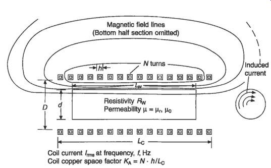
Fig. 14 Diagrammatic section of induction heater for round billet.
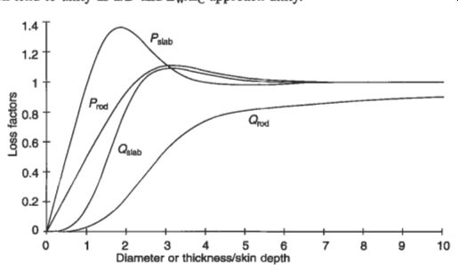
Fig. 15 Loss factors Q and P for rods and slabs.
The power induced in a round solid billet, illustrated in Fig. 14, is given approximately by:
...where the parameters are as shown in Figs 14 and 15. In particular, Qd is shown in Fig. 15 as a function of db, and Kc, the coil shortness factor, is dependent on the ratios dD, dlS and LbVl&. Reference 13C gives empirical values for Kc, which tend to unity as dD and Lw/Lc approach unity.
The power induced in a hollow cylinder of wall thickness t is calculated with Qrd in the above expression replaced by an equivalent factor Qcyl, which is a function of tld, dlband pr. Reference 13B shows graphs of Qcyl for a range of these parameters, although different terminology is used.
Similarly, for a rectangular slab of length L which has a width W much greater than its thickness, the induced power is:
Pw = (N x I x Kc)' x (2W x p)l(b x L) x (U&)' x Qslab (watt)
It is necessary to know the reactive power in the workpiece in order to evaluate the power factor of the coil. This can be calculated by multiplying the induced power by the appropriate P/Q ratio obtained from Fig. 15.
The efficiency of conversion of the electrical power supplied to the coil into thermal power in the workpiece is known as the coil or electrical eficienq, VC. This is given by:
qc = (1 + (l/K:) x (l/KA) x (Sc/Sw) X (pc/pwclr)'" x (l/Q))-' (per unit)
In this formula, Q is the relevant loss factor, KA is the space factor of the coil system and Sc/Sw is the ratio of the coil perimeter to that of the workpiece in the same plane.
This efficiency can be significantly increased by the use of multilayer windings instead of a single-layer coil. Such high-efficiency coils are now commonly used for the heating of non-ferrous billets at mains frequency.
The overall efficiency of induction heating is the product of the supply efficiency? the thermal efficiency and the coil efficiency. Of these, the supply efficiency is typically 0.8-0.9 (per unit); it accounts for losses in cables, power factor correction capacitors and frequency conversion equipment. The thermal efficiency has typical values in the range 0.7-0.9 (per unit). This represents the thermal losses from the workpiece, and is critically dependent on the operating temperature, the thermal insulation and the method of operation of the heater.
6.1 Power sources
Loads which can effectively be heated at 50 Hz include slabs, large billets, cylinders and process vessels. Depending on the load rating, the power input is controlled by either an off-load tap changing transformer, or an autotransformer. Power factor correction is usually provided on the primary side of the heater supply transformer, and phase-balancing networks are used to correct the imbalance of large single-phase loads. Voltage transients on the supply network are minimized by the use of soft-start arrangements when switching large loads.
Apart from mains-frequency installations, power supplies for modern induction heaters are derived from solid-state frequency converters. Unit sizes of up to 7 MW have been installed for metal melting at 1-3 kHz, and 1 MW units are now suitable for frequencies up to 500 kHz, previously the domain of power vacuum tube triodes.
6.2 Through-heating of billets and slabs
Induction heating is used extensively for the through-heating of both ferrous and non-ferrous billets prior to rolling, extrusion or forging. The billets, which may be of circular or rectangular section, are either heated individually or passed in line through a series of induction coils. The frequency of the currents, the power input and the length of time in the coil are chosen to provide the right throughput rate and an acceptable temperature distribution over the cross-section of the workpiece.
Metal slabs are also heated by induction processes. One of the largest recent installations is in Sweden; this is rated at 37 MW and heats 15 tonne slabs for rolling at the rate of 85 tonne/hour. Thin slabs, which may be from continuous casting machines or at an intermediate rolling state, are heated at medium frequency.
6.3 Strip heating
The heating of continuous strip metals by the conventional induction method requires the use of frequencies above 10 kHz, and the resulting efficiencies are low for non- ferrous metals. An alternative technique is the transverse flux method by which, for example, an efficiency over 70 percent can be achieved when heating aluminum strip at 250 kHz. The strip is passed between two flat inductors comprising windings in a laminated iron or ferrite core which forms a series of magnetic poles. The flux passes transversely through the sheet and currents are induced in the plane of the sheet. The arrangement of the windings and poles must induce a current distribution which results in a uniform temperature distribution over the sheet as the strip passes through the inductor.
Installations rated at 1.8 MW and 2.8 MW are operating for the heat treatment of aluminum strip in Japan and Belgium respectively.
7. Indirect induction heating
Although induction heating can only be directly effective in electrically conducting materials, it can also provide a means of heating other materials by using a metal as an intermediary, in a way that is analogous to indirect resistance heating. Examples are found in the processing of semiconductors and in the calcining of ceramic materials.
7.1 Semiconductor manufacture Since the energy from the heating coil can be generated in the workpiece without any heat transfer medium, indirect induction heating can be carried out in a vacuum. This is particularly useful in the processing of semiconductor materials.
In one technique, the material is placed in an electrically conducting crucible in the vacuum space. The crucible is directly heated by induction and its heat is transferred to the semiconductor by radiation and conduction.
Semiconductors may also be heated directly by induction without the need for a conducting crucible. In this case very high frequencies up to 4 MHz are used.
7.2 Process heating and calcining
There is an important and growing series of applications in which induction heating is used to heat a vessel or other metal component, from which heat is transferred by conduction to a product.
Examples include:
vessels containing a solid or liquid
pipes through which a liquid flows
chemical reactor vessels
extruders
screw conveyors
rotary kilns
mixer paddles
These applications often employ the coil arrangements already described elsewhere, but there are recent developments using novel techniques. Examples are the 'ROTEK rotary kiln, the heated mixer paddle and the heated screw.
The 'ROTEK kiln is heated by induction and is used for the drying and calcining of granular solids which flow continuously through a revolving drum. The kiln lining and flights are heated directly, and the flights also have the function of lifting or agitating the product as the vessel rotates. The heat is then transferred to the material by conduction. All internal components are made of stainless steel or Inconel, and are heated by the passage of a very large current from end to end. This current is perhaps greater than 20 kA, and cannot be fed through sliding contacts; the drum therefore forms the single-turn secondary of a ring transformer, with a bar primary which passes through its center and returns through the outer copper conductors.
Figure 16 shows the general arrangement. The bar primary is fed from a low- voltage transformer and the efficiency of the device as a heater is very high. Because the ring core can be thermally insulated the operating temperature can be well above the Curie point, and with an Inconel drum, temperatures exceeding 1000°C can be achieved.
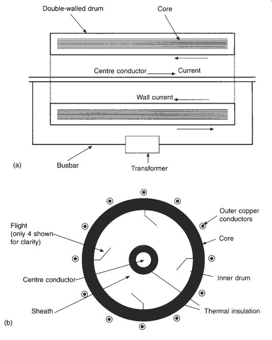
Fig. 16 Operating principle of a ROTEK kiln
8. Dielectric heating
The processing of non-metals by the conventional heating techniques of conduction, convection and radiation is often limited by the physical characteristics of the materials.
Thermal conductivity is a particular problem and since many of these methods depend on the transfer of heat through the product surfaces there is inevitably a temperature gradient between the surface and the center. If the heat flux is raised above a certain level in such circumstances there is a risk that the surface will be damaged by overheating. The choice in many operations is between process inefficiency and product degradation.
Dielectric hearing is a generic term covering radio frequency (RF) and microwave processing. RF and microwave occupy adjacent sections of the electromagnetic spectrum, with microwaves having higher frequency than radio waves. However, the distinction between the two frequency bands is very blurred; for example, some applications at about 900 MHz are described as radio frequency (cellular telephones) and some as microwave (dielectric heating). Nevertheless, RF and microwave heating can be distinguished by the technology that is used to produce the required electric fields. RF heating systems use high-power electrical valves, transmission lines and applicators in the form of capacitors, whereas microwave systems are based on magnetrons, waveguides and resonant (or non-resonant) cavities.
There are internationally agreed and recognized frequency bands which can be used for RF and microwave heating; these are known as the Industrial, Scientific and Medical (ISM) bands. At radio frequencies, the ISM bands are:
0 13.56 MHz f 0.05% (f 0.00678 MHz)
27.12 MHz f 0.6% (f 0.16272 MHz)
40.68 MHz f 0.05% (f 0.02034 MHz)
...and at microwave frequencies the ISM bands are:
the so-called 900 band (896 MHz in the UK, 915 MHz in the USA and Japan, but not permitted in Europe)
2450 MHZ f 50 MHz
Electromagnetic Compatibility (EMC) requirements impose severe limits on any emissions outside these bands. These limits are much lower than health and safety limits and are typically equivalent to microwatts of power at any frequency outside the ISM bands. In most countries, compliance with the relevant EMC regulations is a legal requirement, and this is covered in more detail in Section 15. Often it is the higher harmonics which present the greatest containment problems.
Industrial applications are many and varied, ranging from the drying of textiles to the welding of plastics, the tempering and thawing of meat, the heating of rubber extrusions and the firing of ceramics. Details are given in reference 13D. The heating effect arises from a number of polarizations, the most commonly described being orientation polarization or oscillating dipole, as shown in Fig. 17.
Although this is the principal mode at microwave frequencies, it is of relatively little significance at radio frequencies. The dominant mode in the RF range is space charge polarization, which in turn is dependent on the ionic conductivity of the material being processed. RF can therefore be regarded as a special case of direct resistance heating.
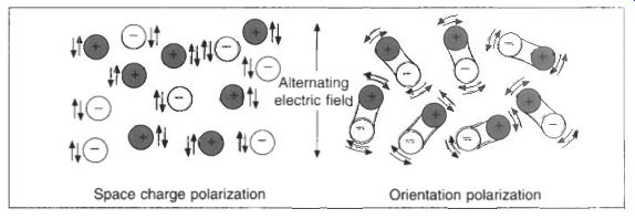
Fig. 17 Orientation polarization and space charge polarization in dielectric
heating
It is possible in theory to choose for any particular material the most appropriate frequency from those available in the industrial, scientific and medical bands. In reality, many products can be processed by either, and the choice between them can be based on other considerations such as the engineering needed to make a satisfactory applicator which is compatible with process line requirements.
The heat transferred per unit volume of product, P, is given by:
P = 2zfq.5,E2 [W/m^2]
where f is the frequency (in Hz), is the permittivity of free space and E is the applied electric field strength (in V/m). q is the loss factor, which is a dimensionless property of the material indicating its susceptibility to heating at the given frequency; the loss factor varies with moisture content, temperature and other factors.
8.1 Radio frequency power sources and applicators
Most RF power supplies in the 10 MHz to 100 MHz range are based on a class C oscillator/amplifier. The oscillator valve is most often a triode, which is built into a circuit of inductors and capacitors. When the components are rationalized this circuit can take on the appearance of a tank, which is normally fabricated from aluminum.
With the increasing importance being attached to the need to avoid electromagnetic interference with other equipment, alternative generator types such as crystal-driven oscillators followed by amplifiers are being used. These so-called '50 Q' systems have many other advantages such as controllability and the simplicity of the applicator construction.
RF applicators are essentially capacitors in which the product forms all or part of the dielectric. Figure 13.18 shows three types in which the electric field, for the unloaded condition, is shown by the broken lines.
The simplest and most widely used of these three is the through-field or parallel- plate electrode. In addition to the product there may be in some cases a clearance which forms a series air-space capacitor. Such systems can be used in conjunction with pressure, as in the case of plastic welding, which is still the biggest use of dielectric heating. In this case there is no air gap and the field strength in the load can therefore be relatively high for a given electrode voltage. When plate electrodes are used for operations like drying, an air space is required above the dielectric to allow for the movement of product through the machine and for ventilation of the water vapor. This leads to an increase in voltage between the plates in order to maintain an adequate field strength in the product. It is therefore important to consider the relative dimensions of the dielectric and air-space capacitors so that heating is provided without the risk of an electrical discharge.
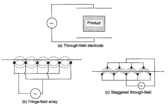
Fig. 18 Radio frequency applicators --- (a) Through-field electrode ; (b)
Fringe-field array; w (c) Staggered through-field
For very thin materials it may be necessary to use an alternative electrode configuration which gives a more suitable distribution. For example, to dry the adhesive on a paper web in the manufacture of envelopes, it is necessary to use the fringe or stray-field array shown in Fig. 13, in which the electric field is arranged to be in the plane of the paper.
For intermediate thickness applications such as post-baking of biscuits it is usual to use a staggered through-field as shown in Fig. 18.
8.2 Microwave power sources and applicators
For industrial microwave heating applications the usual power source is the magnetron.
This is a thermionic device which will launch electrons at a specific frequency when connected to a high-voltage dc source. At the permitted operating frequency of 2450 MHz, the highest output from a magnetron until recently was 5 kW, but 15 kW units are now becoming available. For the '900' band high-efficiency magnetrons of up to 60 kW now exist. Where higher powers are needed, a number of magnetrons may be fed into one applicator.
The most common form of industrial heating oven is the multimode oven, which is essentially an enlarged version of the familiar domestic microwave oven; in the case of continuous processing this will have appropriate product ports to allow the passage of product but confine the microwave within the oven. In such applicators the antenna of the magnetron may be mounted directly into the oven, but more often the microwave power is transmitted from the power supply via waveguides to the oven cavity, where it is launched into the chamber. Other options for microwave applicators include directional horns and 'leaky waveguides I. Industrial microwave heating has been used extensively in the rubber industry for curing and preheating prior to molding. In the food industry it has been used for tempering, melting, cooking and drying. Microwave vacuum dryers have recently been developed for drying expensive, high-quality pharmaceuticals which are temperature sensitive.
9. Ultraviolet processes
Inks and surface coatings can be cured at high rates with ultraviolet sources. The coatings are specially formulated using monomers with photo-initiators, so that a very rapid polymerization is brought about on exposure to ultraviolet radiation.
Although this is not strictly a heating process, it has much in common with infrared heating for drying or cross-linking and is very often in direct competition with infrared.
The energy usage in ultraviolet is much lower than in infrared because the process requires only the stimulation of a reaction which is overall exothermic.
The active spectral region covers the wavelength range 250400 nm in the ultraviolet, and visible wavelengths in the range 400-500 nm may also be used. The distribution can be confined to a few intense and narrow bands of wavelength. A typical output spectrum from a medium-pressure (sometimes called high-pressure) mercury vapor discharge lamp is shown in Fig. 19. Additional spectral bands can be generated by incorporating metal halide dopants in the lamp fill. The power ratings of these lamps are in the range 2-20 kW, over active lengths of 250-1800 mm.
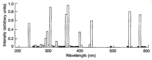
Fig. 19 Spectral output from a medium-pressure mercury lamp
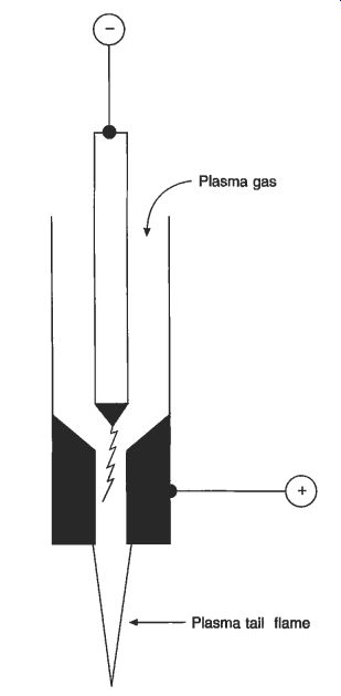
Fig. 20
Rod and nozzle type of plasma torch
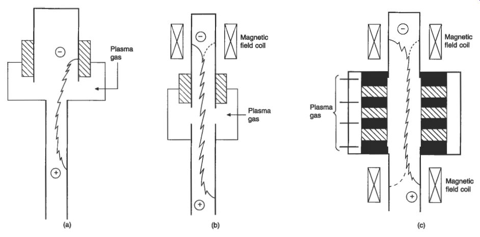
Fig. 21 Linear coaxial tubular electrode types of plasma torch construction:
(a) The Hiils type developed from Schoenherr's original early design: (b) A
typical 2 MW non- transferred torch (c) A typical stretched or segmented torch
rated at 6 MW or higher
10. Plasma torches
The plasma torch uses an electric arc discharge to generate a thermal plasma, which is a partially ionized gas in which the degree of ionization is linked to the temperature of the gas. Here the temperature of the gas rises above 6000°C; the gas becomes a reasonably good conductor of electricity. Temperatures in the core of an arc may reach 20 000°C or higher.
The torches that are used in electroheat applications may be broadly classified into the three families:
--rod and nozzle electrode types. An arc burns between the end of a rod and the internal surface of a nozzle, and gas is blown around the arc and through the nozzle. Figure 20 shows the general layout. The supply is usually dc, but torches designed for ac use are also available.
--linear coaxed tube types. The arc burns between the internal surfaces of tube electrodes, and gas is blown through the electrodes around the arc.
Figure 21 shows the arrangement. The power handling capacity is improved as the arc root motion is induced by the imposition of axial magnetic fields.
--electrodeless types. These include particularly induction-coupled and microwave types. An induction-coupled arc burns in a ring-shaped electric field which is induced within a coil-carrying current typically at a frequency of a few MHz; the arrangement is shown in Fig. 22. The arc plasma is effectively the workpiece in an RF induction heater. In microwave torches the arc is maintained by currents which are driven by microwave fields in a resonant cavity. Peak plasma temperatures in electrodeless torches are typically within the range 7000-11000C, which is rather lower than for the electrode types.
Transferred torches are available for industrial applications at power ratings up to about 7 MW in a single torch. Non-transferred torches are available in power ratings up to about 100 Mw, but for industrial applications a maximum rating of about 10 MW is imposed by practical considerations of electrode life. The efficiency of non-transferred torches may reach 90 percent for coaxial-tube electrode types used with high gas-flow rates, corresponding to relatively low gas temperatures of 3000-4000°C. Rod and nozzle types are generally used for lower power ratings up to about 100 kW, and their efficiency tends to be lower, being about 60 percent at best.
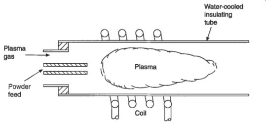
Fig. 22 An induction-coupled plasma torch
10.1 Plasma furnaces or reactors
In principle, the simplest type of furnace or reactor s the 'in-flight' reactor in which the input materials are injected directly into the plasma stream or even into the torch, and the required processes occur with all the reactants suspended in the plasma stream. In-flight reactors generally require the input materials to be gaseous or finely divided because the time available for the process is short, typically of the order of milliseconds.
Transferred plasma torches are commonly used in open-bath furnaces. A return electrode is then usually built into the hearth re-fractories, but three-phase ac and bipolar dc multiple-torch systems have been developed to eliminate the need for the hearth connection.
Non-transferred torches are often used in shaft-type furnaces where a hot reaction zone is created close to the point of injection of the reactive plasma gases in the base of a packed shaft.
Furnaces with rotating shells are also available, the layout being shown in Fig. 23. These are used particularly for the fusion of pure refractory compounds, or when a long residence time is required, as in the treatment of some waste materials.
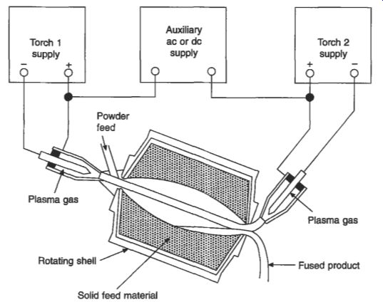
Fig. 23 Rotating shell furnace using a non-transferred torch
11. Glow discharge processes
Glow discharges are being increasingly used for industrial surface coating and surface modification processes.
The characteristic of a glow discharge, from which it derives its name, is that some large portion of the discharge vessel should be filled with a weakly ionized and luminous plasma. The two types of glow discharge are the dc and the low-pressure RF discharge.
12. Lasers
Since its discovery in 1960, the laser has found extensive application in industry for cutting, welding, material removal and heat treatment processes which require power densities above 100 W/mm^2. The principal feature of a laser as a heat treatment source is its monochromatic output, low divergence and high intensity. This enables the parallel monochromatic beam to be focused to a smaller diameter than is possible with other light sources.
Industrial applications for CO2 lasers include the dividing and perforation of substrates for integrated circuits and electronic components, perforation of elastomeric materials, the manufacture of dies for cutting cartons, ready-to-wear suits and thin glass tubes for fluorescent lamps, quartz tubes and borosilicate glass, and for the manufacture of flexigravure plates. Deep-penetration welds can be obtained at power levels above about 1 kW, and the ratio of the weld depth to the heat-affected zone using a laser can be ten times greater than that obtainable with electron-beam welding. Selective heat treatment is also possible.
Table 4 Standards relating to electroheat
13. Standards
Table 4 gives a selection of standards covering the electroheat field, with special emphasis on RF and microwave equipment and methods.