AMAZON multi-meters discounts AMAZON oscilloscope discounts
There are many systems on aircraft that need to be controlled and/or monitored, either manually by the crew, or automatically. A switch provides the simplest form of control and monitoring. For example, the crew need to know if any doors are not closed as part of their pre-flight check; on larger aircraft the position of control surfaces is displayed in the cock pit. Using these two examples, doors can be either open or closed; control surfaces can move through an infinite number of positions (within their nor mal limits of travel). Many other aircraft parameters need to be measured, e.g. temperature and pressure.
Measurements are made by a variety of transducers ; these are devices used to convert the desired parameter, e.g. pressure, temperature, displacement etc. into electrical energy. This section describes generic controls and transducer devices used on aircraft.
1. Switches
The simplest form of switch is the on/off device used to isolate circuits. Other switch types are used to direct the current into pre-determined parts of a circuit. Switches are characterized by:
- number of poles
- number of switched positions
- type of switched contacts (permanent or momentary)
Switches are sometimes guarded or wire-locked with fuse wire to prevent inadvertent operation. Some switch designs have to be pulled out of a detent position before the position can be changed. They are designed to be operated in a number of ways, e.g. toggle, push/pull, rocker or rotary selectors. These switches are designed with multiple contacts; they can be arranged as permanent or momentary contacts.
The toggle switch is a very basic device; FIG. 1 illustrates its internal schematic and external features.
Operating the lever/arm opens and closes switch contacts. Operating levers on toggle switches are some times ganged so that more than one circuit is operated.
The simplest switch has two contact surfaces that provide a link between circuits; these links are referred to as poles . Switch contacts can be normally open or closed and this is normally marked on the switch (NO/NC). The number of circuits that can be linked by a single switch operation is called the throw . The simplest form of switch would be single pole, single throw (SPST). Schematics of switch configurations commonly found in aircraft are illustrated in FIG. 2 .
Some switches are designed with instinctive tactile features so that the risk of selecting the wrong system is minimized, e.g. the flap up/down switch-operating lever would be shaped in the form of an aerofoil; the undercarriage selection switch-operating lever would be shaped in the form of a wheel.
Push/pull-operated switches incorporate a spring to hold the contacts open or closed; the switch contacts are therefore push-to-make or push-to-break . Rocker switches (FIG. 2b) combine the action of toggle and push/pull devices. Rotary switches are formed by discs mounted onto a shaft; the contacts are opened and closed by the control knob.
1.1 Combined switch/light devices
Modern aircraft panels utilize a combined switch and light display; the display is engraved with a legend or caption indicating system status. These can be used in a variety of ways e.g. to show system on/off. The switch portion of the device can be momentary or continuous; small level signals are sent to a computer or high-impedance device. Internal backlighting is from two lights per legend for redundancy; these are projected via colored filters. The two captions provide such information as press to test (P/TEST). Examples of combined switch/light devices are given in FIG. 3
Test your understanding
Explain the switch terms ' throw ' and ' pole ' .
========
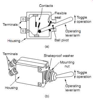
FIG. 1 Toggle switch: (a) internal schematic, (b) external features
Contacts; Flexible seal; Toggle operation; Operating lever/arm; Ball pivot; Housing Terminals (a) (b) Shakeproof washer; Mounting nut; Toggle operation Operating lever/arm; Terminals Housing
=========
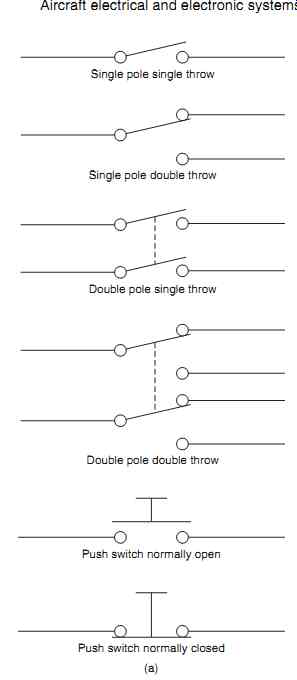
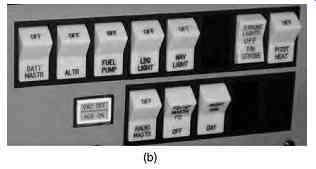
FIG. 2 (a) Switch configurations, (b) rocker switches; Single pole single
throw; Double pole single throw; Double pole double throw; Single pole
double throw; Push switch normally open; Push switch normally closed (a)
=========
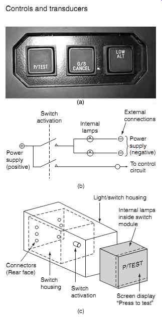
FIG. 3 Combined switch/light: (a) typical installation, (b) electrical
schematic, (c) external features
Switch activation; Internal lamps; Power supply (positive); Power supply (negative); To control circuit; External connections (b) Light/switch housing; Internal lamps inside switch module; Screen display; "Press to test" P/TEST; Connectors (Rear face); Switch activation; Switch housing (c)
=========
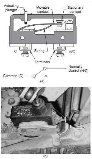
FIG. 4 Micro-switch schematic: (a) internal schematic, (b) external features
Spring; Terminals; Stationary contact; Movable contact; Actuating plunger (a) C N/C Common (C); Normally closed (N/C)
=========
1.2 Micro-switches
These are used to sense if a device has moved or has reached its limit of travel, e.g. flap drive or undercarriage mechanisms. Figure. 4 illustrates the internal schematic and electrical contacts of a typical micro switch product. The contacts open and close with a very small movement of the plunger. The distance travelled by the armature between make/break is measured in thousandths of an inch, hence the name 'micro'. A snap action is achieved with a contact mechanism that has a pre-tensioned spring.
Micro-switches are attached to the structure and the wiring is connected into a control circuit. An example of micro-switch application is to sense when the air craft is on the ground; this is achieved by mounting a micro-switch on the oleo leg . When the aircraft is on the ground, the oleo leg compresses and the switch is operated. Micro-switches are used to sense the mechanical displacement of a variety of devices, including:
- control surfaces
- undercarriage
- pressure capsules
- bi-metallic temperature sensors
- mechanical timers
Proximity switches perform the same function as micro-switches; they sense the presence of an object by the interruption of a magnetic circuit. There are two types of proximity switch: reed and solid state.
The reed switch device comprises two hermetically sealed sections as illustrated in FIG. 5. One section (the actuator) contains a magnet; the other section (the sensor) contains a reed armature with rhodium-plated contacts. The usual arrangement is for the sensor unit to be fixed to the aircraft structure; the actuator is attached to the item being monitored, e.g. a door.
When the gap between the actuator and the sensor reaches a pre-determined distance, the reed contacts close thereby completing the circuit. They open again when the actuator and sensor are moved apart.
The solid state proximity switch is based on an inductance loop and steel target as illustrated in FIG. 6. This inductance loop is the input stage of an electronic switch unit incorporated as part of the actuator.
As the target moves closer to the coil, the inductance of the coil changes. An electronic circuit determines when the inductance has reached a pre-determined level. The obvious advantage of this type of switch is that there are no switch contacts, hence higher reliability.
1.3 Proximity switch electronic unit
Some aircraft are installed with a proximity switch electronic unit (PSEU). This unit receives the position of various items, e.g. flaps, gear, doors, etc and communicates this information to other systems including:
- take-off and landing configuration warnings
- landing gear position indicating and warning
- air/ground relays
- airstairs and door warnings
The PSEU is integrated with the master caution sys tem, and used to indicate if a problem exists that has to be corrected before flight. (The above systems are discussed in subsequent sections.)
Key point
Typical applications for micro-switches and proximity switches include sensing the positions of flaps, gear, doors etc. On a large transport aircraft there can be up to 100 such devices.
Key maintenance point
The maintenance engineer will often need to adjust micro-switch or proximity switch positions to ensure that they are correctly positioned; this will compensate for any displacement of the switch.
Test your understan ding
What is the difference between proximity and micro-switches?
=========
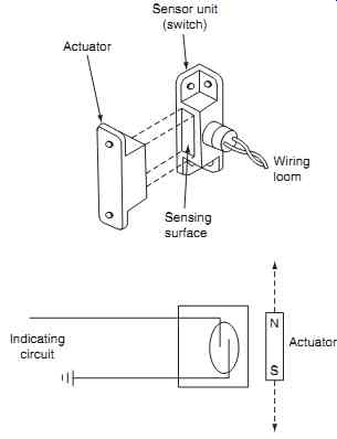
FIG. 5 Proximity switch (reed type) schematic
Sensor unit (switch); Actuator; Sensing surface; Wiring loom N S; Indicating circuit; Actuator
=========
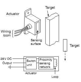
FIG. 6 Proximity switch (solid state)
Schematic; Target; Target Wiring loom, Proximity sensing network, Switch unit, Sensing surface, Actuator; Actuator, Loop 28V DC; Output
=========
2. Relays and contactors
These electromechanical devices interrupt or complete a circuit when activated from a remote source, see FIG. 7 . Changeover relays consist of a coil, moving contact (armature) and external connections.
When the coil has current flowing through it the electromagnetic effect pulls in the contact armature . The armature is pivoted and is held in position by the spring force; with no current flowing, the armature returns to its original position by the spring force.
Contactors operate in the same way; the difference between them is their physical construction and application. Relays are generally used for low current applications; contactors (also known as breakers) are used for switching higher currents, e.g. for connecting battery power to the aircraft. The features of a contactor include the main power contacts and auxiliary contacts used for indication and control of other devices, e.g. lights and relays in power distribution systems (contactors/breakers are described in this context in Section 8).
Reed relays are used in control circuit applications; they are generally found within components, e.g. mounted onto printed circuit boards. Figure. 8 illustrates the principles of a reed relay. Slugged relays have delayed operating times and are needed in specialized applications. The delay in opening/closing the contacts is achieved by a second coil wound around the main coil; the turns are arranged such that the build up of magnetic flux in the main coil is opposed by the build up of magnetic flux in the secondary coil.
2.1 Relay configurations
The simplest relay has two contact surfaces that pro vide a link between circuits; these links are referred to as poles . Relay contacts can be normally open or closed (NO/NC) and this is normally marked on the body of the relay. The number of circuits that can be linked by a single relay operation is called the throw . The simplest form of relay would be single pole, single throw (SPST). Relay configurations commonly found in aircraft are illustrated in FIG. 9 . Typical relay installations on a general aviation aircraft are shown in FIG. 10.
Key maintenance point
The pull-in voltage of a relay is the specified voltage need to attract the armature and close or open the switch contacts.
Key maintenance point
The drop-out voltage of a relay is the specified point at which the armature returns to its relaxed position when the magnetic force is overcome by the spring force.
=======
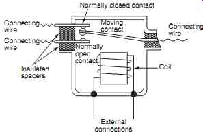
FIG. 7 Changeover relay schematic
Coil; Normally; closed contact; Moving contact; Normally open contact; Connecting wire; Connecting wire Connecting wire; Insulated spacers; External connections
========
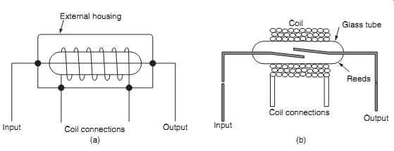
FIG. 8 Reed relay schematic (a) external schematic, (b) internal schematic
External housing; Coil connections; Input; Output (a) (b) Coil; Coil connections; Input; Output; Glass tube; Reeds
========
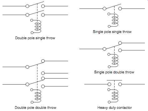
FIG. 9 Relay configurations
Double pole single throw; Double pole double throw; Heavy duty contactor; Single pole double throw; Single pole single throw
========
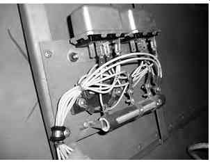
FIG. 10 Relay installation (GA aircraft)
2.2 Polarized relays
These are used in control circuits with very low volt ages or currents; the relay is extremely sensitive and can respond to levels in the order of mA/mV. This low level is often not suitable for the conventional spring loaded armature device since (at very low pull-in/ drop-out voltages) the contacts would chatter , leading to spark erosion. Polarized relays use magnetic forces to attract and repel the armature instead of a spring force. The armature is a permanent magnet, pivoted between two pole faces formed by the frame of high permeability material. When current flows, the poles change and the frame becomes an electromagnet; this exceeds the force exerted by the permanent magnet and the armature changes position. In this position the N-S poles form a strong attractive force and the armature is retained in position. If the supply is interrupted the electromagnetic force is reduced to less than the permanent magnet and the armature returns to its original position.
Key maintenance point
Contacts in relays and contactors are made from silver alloy. The contacts need to have sufficient current flowing/switching to provide 'wetting ' of the contacts. In-service problems and failure associated with these contacts include:
• contact erosion
• welded contacts
• contact corrosion
3. Variable resistors
Variable resistors are mounted on a linear slider or rotary shaft to provide a user-adjustable resistance; typical applications include the control of lighting, audio volume or generator regulator trimming. They are sometimes combined with micro-switches to provide an on/off control function. Variable resistors are produced as either:
- potentiometers
- preset resistors
- rheostats
FIG. 11 provides some examples of symbols used for variable resistors. When the intention is for the pilot or maintenance engineer to adjust the circuit resistance for control purposes, e.g. audio volume or lighting intensity, the variable resistor device is used.
If the circuit resistance is only intended to be adjusted in the workshop, a preset device is used.
A potentiometer (often called a ' pot ' for short) is a type of variable resistor that is normally used as a voltage divider ; this is a circuit used to supply a portion of the power supply voltage from a resistive con tact. The potentiometer is typically a three-terminal resistor with a sliding center contact (the wiper). If all three terminals are used, it can be used in the volt age divider application. If only two terminals are used (one end of the resistor and the wiper), it acts as a variable resistor.
Key maintenance point
Corrosion or wearing of the sliding contact can lead to audio volume or lighting intensity problems, especially if the center contact (the wiper) is kept in one position for long periods.
Key point
A rheostat performs the same function as the potentiometer, but is physically much larger, being designed to handle much higher voltage and/or current. Rheostats are constructed with a resistive wire formed as a toroidal coil, with the center con tact/wiper moving over the surface of the windings.
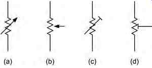
FIG. 11 Variable resistors: potentiometers, preset or rheostats
4. Linear displacement transducers
Many aircraft parameters need to be measured, including: speed, altitude, temperature and pressure.
Measurements are made by a variety of transducers; these are devices used to convert the desired parameter into an electrical signal that can be used in a control system and/or display.
4.1 Solenoids
The solenoid is a type of transducer that converts electrical energy into linear displacement . Typical applications include the actuation of pneumatic or hydraulic valves. They are electromechanical devices, consisting of an inductive coil wound around a steel or iron armature . The coil is formed such that the armature can be moved in and out of the solenoid's body. The armature is used to provide the mechanical force required to the item being moved.
4.2 LVDT
The linear variable differential transformer (LVDT) is a transducer used for measuring small linear displacements. The LVDT has three transformer windings located within a housing; the center coil is the primary winding; the two outer coils are the secondary windings, see FIG. 12 . A ferromagnetic core, connected to the item being measured, moves along the axis of the housing. The 26 VAC 400 Hz supply is connected to the primary windings, causing a voltage to be induced in each of the secondary windings proportional to its mutual inductance with the primary.
When the core is displaced from its neutral position, the mutual inductances change, causing the volt ages induced in the secondary windings to change.
The coils are wound such that the output voltage is the difference between the two secondary output volt ages. When the core is in its neutral position (equidistant between the two secondaries) equal and opposite voltages are induced in the two secondary coils, so the output voltage is zero.
========
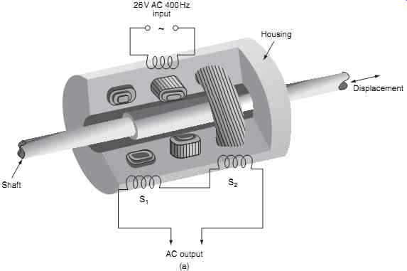
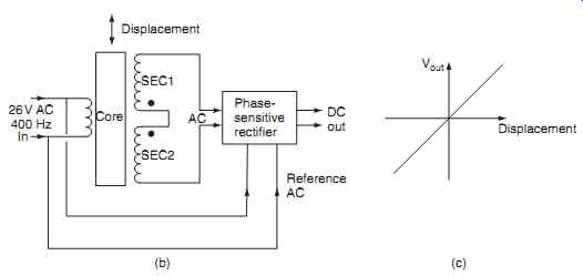
FIG. 12 Linear variable differential transformer (LVDT) (a) mechanical
schematic (b) electrical schematic (c) output voltage vs displacement
Core 26V AC 400 Hz SEC1; Displacement; SEC2 AC DC out Reference AC; Phase sensitive rectifier; Vout Displacement ~ 26V AC 400Hz input; Housing Displacement S2 S1; Shaft AC output (a) (b) (c) In
========
When the core is displaced, the voltage in one secondary coil increases as the other decreases; the resulting output voltage starts to increase in phase with the primary voltage. When the core moves in the opposite direction, the output voltage increases, but is out of phase with the primary. The output voltage is therefore proportional to displacement of the core; the output voltage phase is used to determine the direction of movement. This AC output is then fed into a phase sensitive rectifier; the phase difference is then indicated by the _ /_ polarity of the DC output.
4.3 EI sensor
Another device used for measuring very small movements in control systems is the EI sensor. This device gets its name from the shapes of the fixed E and pivoted I laminated cores, see FIG. 13(a) . The center limb of the E core is wound with the primary turns of a transformer; the outer limbs of the E core are wound with the secondary turns, see FIG. 13(b) . These are wound in series, and in opposition to each other. The I bar is connected mechanically to the device being measured for displacement, e.g. a pressure capsule; it is pivoted and wound with a coil that is connected to a reference power supply.
With the I bar in a neutral position:
- the air gaps at each end are equal
- the magnetic flux is equal
- equal and opposite voltages are generated in the outer limbs
- the output from the sensor is zero
Referring to the schematic in FIG. 14 , when the I bar moves, the air gaps become unequal, causing the reluctance to change. Flux in one limb (with the smaller gap) increases, flux in other limb decreases.
The induced voltages change; the output voltage is amplified for use in a control system. This measures the phase angle and magnitude of the EI sensor.
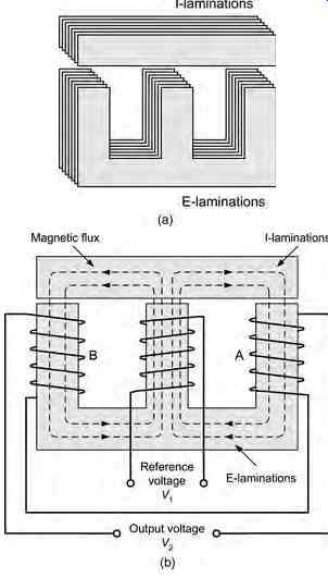
FIG. 13 EI sensor - general arrangement: (a) core arrangement, (b) core
windings
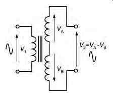
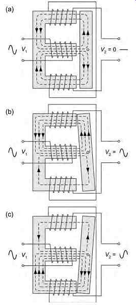
FIG. 14 EI sensor operation