AMAZON multi-meters discounts AMAZON oscilloscope discounts
Electrical power is supplied to the various loads in the aircraft via common points called busbars. The electrical power distribution system is based on one or more busbar(s); these provide pre-determined routes to circuits and components throughout the aircraft. The nature and complexity of the distribution system depends on the size and role of the aircraft, ranging from single-engine general aviation through to multi-engine passenger transport aircraft. For any aircraft type, the distribution system will comprise the following items:
- busbar
- protection
- control
- wiring
- loads
In this section, we will focus on busbar configurations and how these are arranged for the protection and management of the various power supply sources available on the aircraft.
The word ' bus ' (as used in electrical systems) is derived from the Latin word omnibus meaning ' for all ' . Busbars are often formed from thick strips of copper, hence the name ' bar ' . These have holes at appropriative intervals for attaching one side of the protection device (circuit-breaker or fuse). Alternatively, they are made from heavy gauge wire. The busbar can be supplied from one or more of the power sources previously described (generator, inverter, transformer rectifier unit or battery). Protection devices, whether fuses or circuit-breakers, are connected in series with a specific system; they will remove the power from that sys tem if an overload condition arises. There also needs to be a means of protecting the power source and feeder lines to the busbar, i.e. before the individual circuit protection devices. The various methods used for air craft power supply distribution for a wide range of air craft types are described in this section.
======
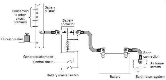
FIG. 1 Battery busbar schematic
Battery; Battery master switch Battery contactor; Battery busbar; Generator/alternator; Control circuit; Earth connection; Air frame section; Earth return system; Connection to other circuit breakers; Circuit breaker
======
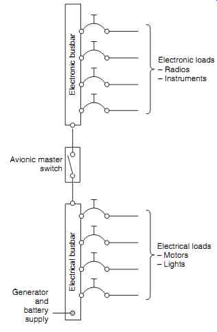
FIG. 2 Split avionic bus schematic: Generator and battery supply
Electronic loads:
- Radios
- Instruments
Electrical loads:
- Motors
- Lights Electronic busbar Electrical busbar
-Avionic master switch
=======
1 Single engine/general aviation aircraft
A simple busbar distribution system is fed by the battery and controlled by a battery master switch , see FIG. 1. Since the current supplied from the battery to the bus will be very high, a heavy-duty relay or contactor is often used; the battery master switch activates the contactor when power is required on the bus.
The same switch is also used for generator control.
For general aviation aircraft the battery is normally used for an engine start. The connection for this is taken before the bus to minimize voltage drop (IR) losses. A variation of the simple battery bus is the split avionic bus , see FIG. 2 . This arrangement isolates electronic devices from heavy surges during engine start, or when using external power to start the engine. The arrangement for an AC generator system is shown schematically in FIG. 3 . This illustrates the voltage regulator and battery master switch used for alternator control. It is normal practice for the battery charge/discharge current to be monitored via an ammeter.
For certification purposes, it is often a requirement that no single failure of any component should cause loss of power to the radios. One way of achieving this is supplying the bus from the main contactor and an emergency switched contact.
1.1 Reverse current relay
This circuit arrangement is needed on any DC generation system to prevent the battery from feeding excess current back through to the generator's armature. Without this protection, the battery would discharge when the generator output voltage is less than battery terminal voltage, e.g. during engine shut down. An automatic method is needed to disconnect the generator from the battery under these conditions.
Many circuits have been developed, some are stand alone, some are integrated with other generator functions within the same unit e.g. voltage regulation. To illustrate the principles of the reverse current relay, an electromechanical device is described.
Referring to FIG. 4 , voltage and current coils are wound onto the same soft-iron core. The voltage coil comprises many turns of fine gauge wire; this is connected in parallel with the generator output. The cur rent coil is made of a few turns of thick gauge wire; it is connected in series with the generator output. The combined coils and core form an electromagnet.
A pair of high-current-rated switch contacts are held open by the force of a spring; the contacts can be closed by an armature that is controlled by the influence of the electromagnet's field.
When the generator output is higher than the terminal voltage of the battery, the contacts are held closed by the magnetic field created by the current in both the coils. (These are wound such that the magnetic fields assist each other.) If the engine is slowed down to the point where the generator output is less than the terminal voltage of the battery, the contacts are opened since current is now flowing through the current coil in the opposite direction (the electromagnetic field is weakened as a result). With the contacts open, the battery is effectively disconnected from the generator.
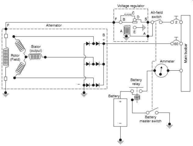
FIG. 3 Alternator/busbar schematic
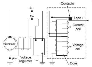
FIG. 4 Reverse current relay
1.2 Current limiter
This device reduces the output from a DC generator under fault conditions, e.g. a short circuit on the busbar, to protect the generator from overheating and burning out its windings. The limiter reduces generator output if its maximum safe load is exceeded; if the fault condition is removed, the generator automatically becomes available again. It operates on a similar principle to the electromechanical voltage regulator; as with the reverse current relay, it could be a stand-alone device or be built into a generator control unit. To illustrate the principles of the current limiter, an electromechanical device is described.
Referring to FIG. 5, the current coil is connected in series with the output of the generator. If the out put exceeds a pre-determined limit, the coil's magnetic field opens a pair of switch contacts; this puts a resistor in series with the generator's field thereby reducing the generator's output. This decrease in generator output weakens the field of the current coil and the contacts close again (shorting out the resistor). If the fault condition has been removed, the generator remains connected to the bus. Should a permanent overload condition exist, the contacts open/close on a repetitive basis to keep the output within safe limits.
Test your understanding
Explain the different functions of a reverse current relay and current limiter.
=======
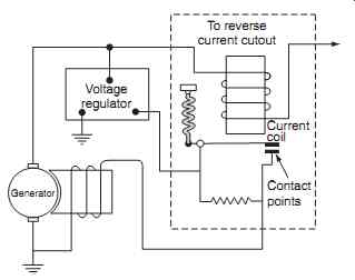
FIG. 5 Current limiter Master
Generator; Voltage regulator; To reverse current cutout; Current coil; Contact points
========
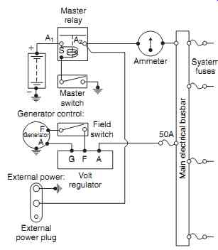
FIG. 6 External power supply schematic
Ammeter; Master relay; Generator control: Volt regulator; 50A; System fuses; Main electrical busbar; External power plug; External power: Field switch A1 A2; Master switch; F FG S A A Generator
========
1.3 External power
The aircraft battery provides an autonomous means of starting the engine. Certain types of operation, e.g. cold weather and repeated starts, could lead to excessive demands, resulting in a battery that is not fully charged. An external power supply system schematic (as illustrated in FIG. 6 ) provides power to the air craft, even when the battery is flat, or not installed.
External power can be from a ground power unit or simply from a battery pack as shown in FIG. 7. On larger aircraft installations, a connector with three sockets supplies external power. These sockets connect with three pins on the aircraft fuselage as shown in FIG. 8. Different-size pins are used on the connectors to prevent a reverse polarity voltage being applied.
Some aircraft installations have a ground power relay . Power can only be supplied into the aircraft via the main pins when the third (shorter) pin makes contact. The third pin is used to energize the ground power relay; this additional relay prevents arcing on the power connector as illustrated in FIG. 9 . External AC power is applied in a similar way, except that the three phases have to be connected via individual circuits.
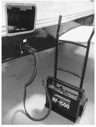
FIG. 7 External ground power from a battery pack.
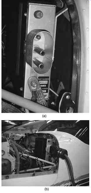
FIG. 8 External ground power: (a) external ground power 3-pin connector,
(b) external ground power connected.
1.4 Battery charging: single engine
Battery charging on the ground is achieved by an external power supply (it would be unsafe to run the engine in the hangar). External power in the form of another battery, a diesel-powered generator or adapted mains supply provides a source of energy.
With external power available and switched on, power is now available at the battery relay output terminal via the external power relay. Power is also supplied to the closing circuit (the resistor and diode reduces the charging voltage). When the battery master switch is selected on, this closes the battery relay thus providing full charging current. Protection against a short circuit battery is from a fuse.
Test your understanding
What kind of instrument would be used to measure battery charging/discharging current?
2 Twin engine general aviation aircraft
In the basic configuration, each engine drives its own generator, and the outputs are supplied to a common battery busbar. Engine speed variations mean that one generator could be supplying more output than the other generator and so an equalizing system, using carbon pile regulators, is employed to balance the out puts. This balancing circuit provides automatic adjustment so that each generator delivers an equal output.
Referring to FIG. 10 , the left and right carbon pile regulators (items 3 and 4) each have equalizing coils (items 7 and 8) wound on the same core as the voltage regulator coils (items 5 and 6). Low value resistors (items 1 and 2, typically 0.01 Ohm) are fitted in each generator ground connection; these develop voltage drops in proportion to the generator output currents.
Both equalizing coils are connected in series with the top end of the resistor; the system senses and adjusts the generator outputs to balance both generators at normal engine speeds. The generator outputs are connected through the reverse current relays (items 11 and 12) to the battery busbar. Equalizing circuits connect each resistor via equalizing coils and equalizing switches (items 13 and 14). When each generator has the same output, e.g. 50 A, the voltage dropped across each resistor is therefore IR _ 5 0 _ 0.01 _ 0.5 V; there is no voltage difference and no current flows in the equalizing circuit, the circuit is now balanced.
Over time, variations in output develop due to the mechanical differences in the regulators, e.g.:
- carbon pile wear
- contact surface resistance
- mechanical variations in the armature.
For illustration purposes, assume that the left genera tor is regulating at an output less than the right genera tor. The voltage dropped across each of the resistors is now different since the left generator is supplying less current. To illustrate this effect, if the left generator is supplying 40 A and the right generator is supplying 50 A, the voltage drops across the respective resistors are: […].
This difference in voltage (0.1 volt) causes a current to flow from R2 through the right equalizing coil (8) into the left equalizing coil (7). This relaxes the right car bon pile regulator thereby decreasing the generator out put. The left regulator coil compresses thereby increasing the left generator output. In practice, this circuit can only compensate for relatively small variations in output; the generators need to be trimmed on a periodic basis.
=====
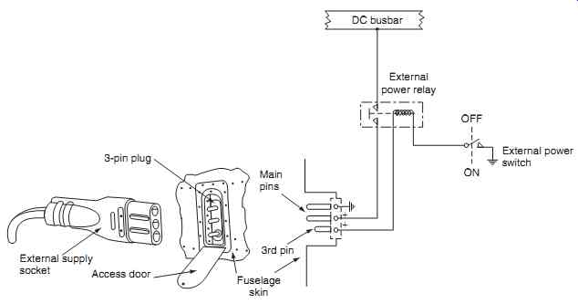
FIG. 9 External ground power 3-pin connector schematic
External supply socket 3-pin plug; Main pins; Access door; Fuselage skin 3rd pin; DC busbar; External power relay; External power switch; OFF ON
=====
3. Larger aircraft systems
Larger (commuter, business and passenger) aircraft have many more electrical systems compared with general aviation aircraft; there is s requirement for a comprehensive approach to account for potential failures of generators, wiring, etc. The management of potential failures is addressed by categorizing the various loads and then disconnecting them in accordance with a predetermined sequence. The process of switching loads off the bus is called load-shedding ; this can be achieved by automatic or manual control.
These loads are connected onto specific busbars that fulfill a specific function. These can be categorized into a hierarchy as illustrated in FIG. 11. Connections between busbars are via heavy-duty contactors, or breakers. Aircraft types vary, however the following categories are typical for many installations.
Main bus: this is sometimes called the non-essential, generator, or load bus. It will include loads such as the galleys, in-flight entertainment ( IFE) and main cabin lights. These loads can be disconnected and isolated in flight without affecting the safe operation of the aircraft.
Essential bus : this is sometimes called the vital or safety bus. It will include equipment and instruments required for the continued safe operation of the aircraft.
Battery bus: this is sometimes called the standby, or emergency bus. It supplies the equipment required for the safe landing of the aircraft, e.g. radios, fuel control, landing gear and fire protection.
There are three main types of distribution system architecture used on aircraft to fulfill the above:
- split bus system
- parallel system
- split parallel system
=========
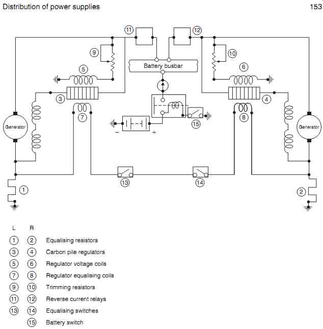
FIG. 10 Simple twin engine equalizing system schematic
Equalizing resistors; Carbon pile regulators; Regulator voltage coils; Regulator equalizing coils; Trimming resistors; Reverse current relays; Equalizing switches; Battery switch
=========
4. Split bus system
This is a completely isolated twin generation system, sometimes called a non-parallel system used on twin-engine aircraft, see FIG. 12 . Primary power is based on two main AC integrated drive generators (typically 40 kVA on each engine). An APU generator (40 kVA) is used as back-up in the event of a main integrated drive generator (IDG) failure. Note that the APU is normally a constant speed device in its own right; therefore an IDG is not required. The advantage of a split-bus system is that the generators do not need to be operating at exactly the same frequency and can be running out of phase with each other. Secondary power is derived from step-down transformers to provide 26 V AC; transformer rectifier units (TRU) provide 28 V DC for the DC busbars and battery charging.
========
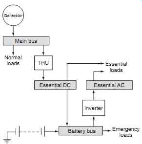
FIG. 11 Large aircraft electrical power hierarchy
Battery bus; Emergency loads Essential loads; Normal loads; Essential DC; Essential AC; Main bus; Generator TRU; Inverter
========
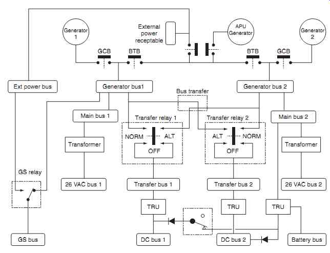
FIG. 12 Split bus system
Referring to FIG. 12, the right and left generators feed their own busbars to which specific loads are connected. Each generator bus is connected to a transfer bus via transfer relays. In the event of a generator failure, the remaining generator (engine or APU) supplies essential loads. Control of the system is via a number of flight compartment switches, control breakers and relays arranged to connect and disconnect the generators and busbars. Typical control panel features for a split bus system are shown in Fig. 13; the features of this panel are:
- Ammeters for the main generators to indicate load current
- Ground power available (blue) when external power supply is connected
- Ground power on/off switch to select ground power onto the aircraft
- Transfer bus off (amber) when the transfer relay is de-energized (either normal or transfer)
- Bus off (amber) both respective generator circuit breakers (GCB) and bus tie breakers (BTB) open
Generator bus off (blue) if the respective GCB is open APU generator bus off (blue) APU running at 95% RPM, no power from generator.
Key maintenance point
External AC power cannot be paralleled with the aircraft generators