AMAZON multi-meters discounts AMAZON oscilloscope discounts
(cont. from part 1)
5. Parallel bus system
The electrical distribution system on larger passenger aircraft (with three or four engines) are based on a parallel load distribution system, see FIG. 14. In this configuration, all generators are connected to their own AC load bus and a distribution bus; any generator can supply any load bus to provide equal load-sharing.
All generator voltages, frequencies and phase relation ships must be controlled to very close tolerances. Any attempt to connect generators in parallel before these conditions are met could result in loss of generator power due to large circulating currents. Referring to FIG. 14 , when all four GCBs and BTBs are closed; all four generators are synchronized and connected to the tie (or synchronized) distribution busbar.
If one generator fails, its GCB is opened; this isolates the generator from its own load busbar. That busbar is now powered from the remaining generators. If this bus becomes overloaded, opening its GCB FIG. 13 Typical electrical power control panel features and BTB isolates it. With more than two generator failures, load-shed ding is introduced. External power can be made available by one or two power supply units (or carts). The APU can also be connected onto the distribution bus.
6. Split/parallel bus system
This is a flexible load distribution system for large passenger aircraft; it provides the advantages of the parallel system and maintains isolation when needed. Primary power supply features include: one IDG per engine, two APU generators and two external power connections. A split system breaker links left and right sides of distribution system. Any generator can supply any load busbar; any combination of generators can operate in parallel.
7. Standby and essential power
Essential 115 VAC power is provided as a single phase supply, see FIG. 15 ; this is selected from one phase of a main busbar. (On a four-engine aircraft, the normal source is the main AC bus number four.) If this normal source fails, a supply is maintained by selecting a different main bus from the remaining systems. The standby AC bus is normally powered from the essential AC bus; if this source fails, a static inverter (supplied from the main battery) is selected to provide standby AC power.
Some aircraft distinguish between battery busbars (that can be disconnected from the battery) and hot battery busbars that are connected directly to the battery, i.e. without any switching; this is illustrated in FIG. 15. This arrangement splits the battery bus with a direct connection (the 'hot' battery bus), and a switched battery bus controlled by the battery switch. Essential DC power is from a transformer rectifier unit (TRU) powered from the essential AC bus. Standby AC and DC bus power is normally from the respective essential supplies; when selected ON, standby AC and DC power is from an inverter and the battery respectively.
Test your understanding
Explain the difference between main, essential and battery busbars.
=========
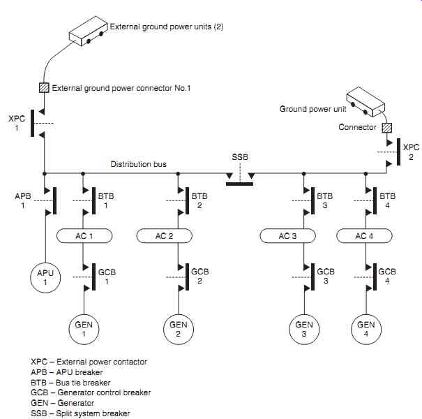
FIG. 14 Parallel load distribution system
XPC - External power contactor APB - APU breaker BTB - Bus tie breaker GCB - Generator control breaker; GEN - Generator; SSB - Split system breaker
==========
8. Battery charging
The battery charger on a large aircraft operates from 115-volt, three-phase, 400 Hz AC power supplied by the AC ground service bus. A completely discharged nickel-cadmium battery can be recharged in approximately 60-90 minutes. The battery charger operates in one of two modes depending on whether the aircraft is being supplied by external ground power or not.
With the aircraft on the ground, the charger is powered from the ground services bus and provides a constant current to the battery. When the battery's terminal voltage reaches a pre-defined level (adjusted for battery temperature), charging is automatically disconnected. When external power is not available, the battery is charged from a transformer rectifier unit (TRU) that provides 28 V DC to maintain battery charge, and supply loads on the battery bus. The battery's temperature sensor forms part of the charging system to prevent battery damage. If the battery temperature is outside a predefined range (typically -18°C to 60°C), the charging circuit is disconnected.
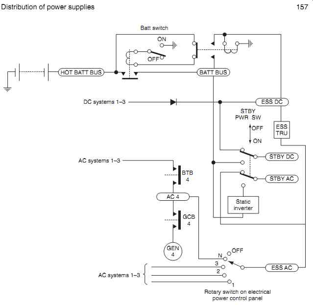
FIG. 15 AC/DC standby and essential power
9. Control and protection
Various components are used for both control and protection of the power distribution system:
- current transformers
- differential current protection
- phase protection
- breakers/contactors
9.1 Current transformers
These are used to sense current for control, protection and indication applications. The primary winding is the main heavy-duty AC feeder cable being monitored; the secondary winding is contained within a housing, see FIG. 16. The secondary windings are in the form of inductive pick-up coils. When current IP flows in the feeder cable, the corresponding magnetic field induces current IS into the secondary windings; this is the output signal that is used by a control, protection or indication device.
9.2 Differential current protection
This circuit detects short-circuits in AC generator feeder lines or busbars; it is a method of protecting the generator from overheating and burning out. Assuming a three-phase AC generator is installed, each phase has its own protection circuit. For illustration purposes, the circuit for a single phase is described. Two control transformers (CT) are located at either end of the distribution system, see FIG. 17. CT1 is located in the negative (earthed) connection of the generator's output. CT2 is located at the output from the busbar performing a monitoring function in a generator control unit (GCU).
If a fault were to develop between the generator and busbar, a current IF flows to ground. The net cur rent received at the busbar is therefore the total generator output current IT minus the fault current ( IF ). The fault current flows back through the earth return system through CT 1 and back into the generator; the remaining current ( IT _ IF ) flows through CT 2 and into the loads. Current transformer CT 1 therefore detects ( IT _ IF ) _ IF which is the total generator current. Current transformer CT 2 detects ( IT _ IF ); the difference between control transformer outputs is therefore IF . At a pre-determined differential current, the generator control relay (GCR) is automatically tripped by the GCU and this opens the generator field.
9.3 Phase protection (Merz Price circuit)
This circuit protects against faults between phases, or from individual phase to ground faults. Connections are shown for protection of a single phase in Fig. 18; a three-phase system would require the same circuit per phase. Two current transformers (CT) are located at each end of the feeder distribution line:
- C T 1 monitors the current output from the generator
- C T 2 monitors the current into the distribution system.
======
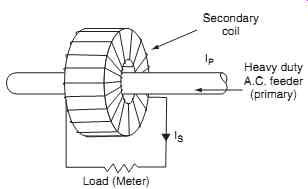
FIG. 16 Current transformer
Secondary coil; Load (Meter) Heavy duty A.C. feeder (primary) IP IS
======
Secondary windings of each current transformer are connected via two relay coils; these windings are formed in the opposite direction. When current flows through the feeder, there is equal current in both coils; the induced EMF is balanced, so no current flows. If a fault develops in the feeder line, current CT 1 flows (but not CT 2 ), thereby creating an unbalanced condition.
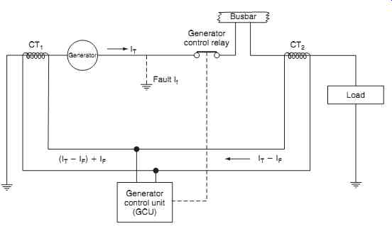
FIG. 17 Differential current protection
Current flow in either of the coils opens the contacts and disconnects the feeder line at both ends.
9.4 Breakers/contactors
Breakers (sometimes referred to as contactors) are used in power generation systems for connecting feeder lines to busbars and for interconnecting various busbars. Unlike conventional circuit-breakers, these devices can be tripped on or off remotely.
Referring to FIG. 19 , they have several heavy-duty main contacts to switch power and a number of auxiliary contacts for the control of other circuits, e.g. warning lights, relays etc.
The breaker is closed by an external control switch via contacts A; the coil remains energized via contacts B to ground. With the coil energized, the main and auxiliary contacts are closed and the spring is compressed. Contacts A latch the breaker closed, assisted by the permanent magnet. When a trip signal is applied (either by a fault condition or manual selection) current flows to ground in the opposite direction. The spring assists the reversed electromagnetic field and this breaks the permanent magnet latch.
A Zener diode suppresses arcing of coil current across the contacts. An electrical power breaker installation is shown in FIG. 20.
========
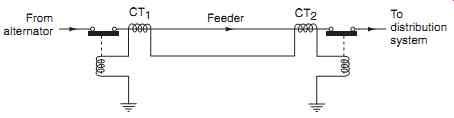
FIG. 18 Phase protection (Merz Price circuit)
To distribution system; From alternator; Feeder; CT1 CT2
========
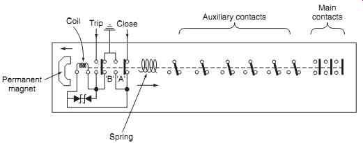
FIG. 19 Electrical power breaker schematic
Auxiliary contacts; Close Trip Coil Spring Permanent magnet Main contacts; 'B', 'A'
========
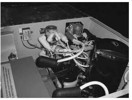
FIG. 20 Electrical power breaker installation
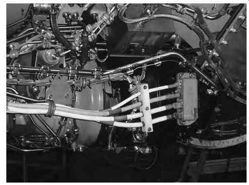
FIG. 21 Generator three-phase output and neutral wires
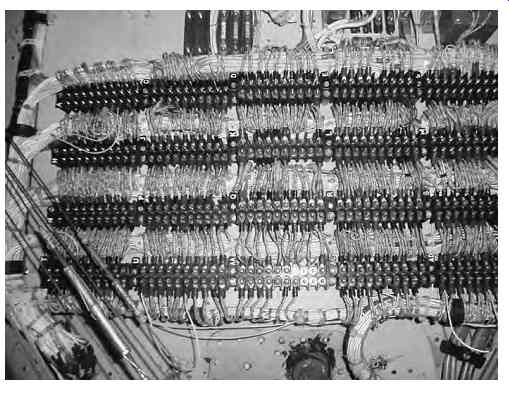
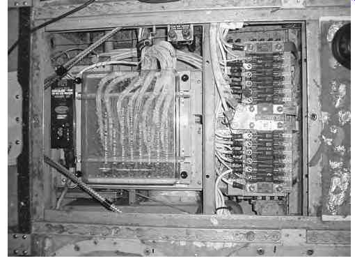
FIG. 22 Typical power distribution
10. Load-shedding
Load-shedding can be defined as deciding on which systems to switch off and in what order this should be done to reduce the power consumption for the remaining power sources. (The worst-case scenario is when the aircraft is operating from the battery alone.) Non essential loads are not required for the safe continuation of flight; these loads include the galleys, in-flight entertainment (IFE) system and main cabin lights as previously described. Essential loads are required for the safe continuation of flight. Emergency loads are required for the safe landing of the aircraft, e.g. radios, fuel control, landing gear and fire protection.
10.1 General aviation aircraft
In small general aviation (GA) aircraft, pilots need to be familiar with the electrical systems of their air craft. Most light GA aircraft are only concerned about an alternator or generator failure. This type of aircraft is normally fitted with an ammeter and/or a voltmeter. On some light GA aircraft an over-voltage light and ammeter can be used to determine the nature of electrical malfunctions. Some aircraft are also fitted with a light that comes on in the event of generator failure, where the battery alone is being used to sup ply the avionic bus. The aircraft battery has a finite capacity; the pilot has to make decisions on the use of the aircraft's power consumption in order to be able to make a safe landing.
10.2 Larger aircraft
More complex aircraft and/or twin-engine aircraft require that pilots have greater knowledge about the electrical systems. Automatic electrical load-shedding is provided on modern aircraft where a control unit detects the loss of electrical power, i.e. the loss of a single or both generators. Automatic load-shedding disconnects specified electrical equipment to maintain sufficient power and systems functionality for the safe continuation of flight.
========
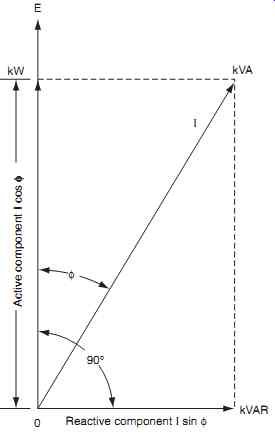
FIG. 23 Components of currents due to phase difference
Reactive component I sin Φ; Active component I cos Φ ;
========
Split bus or parallel systems need to have a centralized means of controlling power distribution. If a generator or bus fault develops, the relevant bus tie breakers (BTB) or generator circuit-breakers (GCB) must be configured to protect the remaining generators, whilst still delivering power to essential loads. Load-shedding is controlled automatically by a solid-state bus power control unit (BPCU). This unit receives inputs from the generator control unit (GCU), ground power control unit GPCU and BTBs, together with control transformers that sense real sys tem current through the main power leads. The BPCU is programmed to detect abnormal conditions and open/close pre-determined BTBs.
Galley power represents a high percentage of the total electrical system's load since it comprises equipment such as beverage makers and ovens. These systems have a major influence on the electrical system's design.
10.3 Load-sharing of AC circuits
It is necessary to discriminate between real and reactive loads in AC load-sharing circuits. Current trans formers in the feeder lines sense each load; these feeder lines are heavy-gauge wires connected to the output of the generator ( FIG. 21). The feeder lines are connected through the various bus hierarchy as described earlier before finally being distributed to the individual loads via smaller-gauge wires and terminal blocks ( FIG. 22 ).
Resistive loads consume real power ; unbalances are corrected by adjusting the generator shaft input power (from the IDG or CSD). Inductive or capacitive loads consume reactive power ; unbalances are corrected by adjusting the generator output via the field current control of the regulator. Apparent power consumed by entire circuit . Reactive power is the vector sum of inductive and capacitive currents and voltages, see FIG. 23 .
- True power is measured in watts (W)
- Apparent power is measured in volt-amps (VA)
- Reactive power is measured in volt-amps-reactive (VAR). Power factor (PF) is the ratio of true and apparent power (W/VA); this is a measure of circuit efficiency.
A power factor of one (unity) is for a purely resistive circuit; a power factor of zero is for a purely reactive circuit. Aircraft generators and inverters are rated in kVA, with a stated power factor over a given range.
11. QUIZ--Multiple choice questions
1. The reverse current relay is needed on any DC generation system to prevent the:
(a) battery from feeding excess current back through to the generator's armature
(b) generator from feeding excess current back through to the battery
(c) battery from feeding excess current to the starter motor.
2. The current limiter device:
(a) increases the output from a DC generator under fault conditions
(b) reduces the output from a DC generator under fault conditions
(c) reduces the output from a DC generator under normal conditions.
3. Battery charge/discharge current is monitored via which type of instrument?
(a) voltmeter
(b) contactor
(c) ammeter
4. Referring to FIG. 24 different size pins are used on external DC power connectors to:
(a) prevent a reverse polarity voltage being applied
(b) prevent excessive power being applied
(c) prevent power being applied when the battery is discharged.
5. The main distribution bus is sometimes called the:
(a) essential bus
(b) emergency bus
(c) non-essential bus.
6. The split bus system is sometimes called a:
(a) non-parallel system
(b) parallel system
(c) standby and essential power system.
7. Inductive or capacitive loads consume:
(a) real power
(b) DC power
(c) reactive power.
8. Essential DC power could be supplied from a:
(a) transformer rectifier unit (TRU) powered from the essential DC bus
(b) transformer rectifier unit (TRU) powered from the essential AC bus
(c) inverter powered from the essential AC bus.
9. Referring to FIG. 25 apparent power is measured in:
(a) volt-amps (VA)
(b) watts (W)
(c) volt-amps-reactive (VAR).
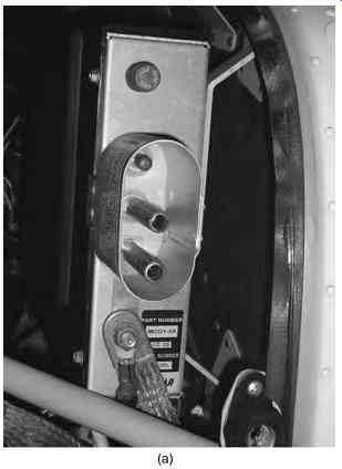
FIG. 24 See Question 4
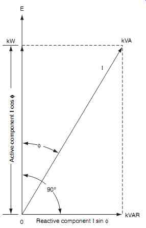
FIG. 25 See Question 9

FIG. 26 See Question 11
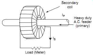
FIG. 27 See Question 12
10. The third pin on external DC power connectors is used to:
(a) charge the battery
(b) energize the reverse current relay
(c) energize the ground power relay.
11. Referring to FIG. 26, this device is a:
(a) external power relay
(b) current limiter
(c) reverse current relay
12. Referring to FIG. 27, this is a schematic diagram for a:
(a) contractor
(b) current transformer
(c) auto-transformer