AMAZON multi-meters discounts AMAZON oscilloscope discounts
The safe and economic operation of an aircraft is becoming ever more dependent on electrical and electronic systems. These systems are all interconnected with wires and cables, and take many forms.
Electrical wires and cables have to be treated as an integral part of the aircraft requiring careful installation; this is followed by direct ongoing inspection and maintenance requirements for continued airworthiness. Wire and cable installations cannot be considered (or treated) as ' fit and forget ' . System reliability will be seriously affected by wiring that has not been correctly installed or maintained. Legislation is being proposed to introduce a new term: electrical wire interconnection system (EWIS); this will acknowledge the fact that wiring is just one of many components installed on the aircraft. EWIS relates to any wire, wiring device, or combination of these, including termination devices, installed in the aircraft for transmitting electrical energy between two or more termination points.
We need to distribute the sources of electrical power safely and efficiently and control its use on the aircraft. Once installed, the wires and cables must be protected from overload conditions that could lead to overheating, causing the release of toxic fumes, possibly leading to fire. This section describes the physical construction of wires and cables together with how they are protected from overload conditions before power is distributed to the various loads on the air craft. (Practical installation considerations for wiring are addressed in Section 20.)
1. Overview
In the first instance, we need to make a distinction between wires and cables . Wires are formed from a single solid conductor or stranded conductors, contained within insulation and protective sheath materials. Cables can be defined as:
- two or more separate wires within the same insulation and protective sheath
- two or more wires twisted together
- any number of wires covered by a metallic braid, or sheath
- a single insulated conductor covered by a metallic outer conductor (co-axial cable).
The terms wires and cables are often interchanged.
In this guide, reference will be made to ' wiring ' in the all-embracing generic sense; cables will be referred to in specific terms as and when required.
Key maintenance point
Wire and cable installations cannot be considered (or treated) as 'fit and forget '. System reliability will be seriously affected by wiring that has not been correctly installed or maintained.
1.1 Types of wire and cable
There is a vast range of wires and cable types used in an aircraft; these can be categorized with their specific uses and applications:
- airframe wires and cables
- equipment wires and cables
- ignition system cables
- thermocouple cables
- data bus cables
- radio-frequency (RF) cables.
This section addresses airframe wire and cable applications in detail. (Wiring inside of equipment is not specifically addressed.) The application of ignition and thermocouple cables (engine systems). Wires or cables designed for small signals, e.g. data bus cables carrying digital data, are screened to prevent their signals from being affected by electromagnet interference. Wires and cables that carry high power and/or high frequencies are also shielded to prevent them being the cause of electromagnetic interference. Screening and shielding to protect against electromagnetic interference (EMI) and electromagnetic compatibility (EMC) are described in this section; the subject of EMI/EMC protection is discussed in more detail in Section 19.
Radio-frequency (RF) cables (or feeders) are specialized types of screened cables. (These are described in more detail in a related guide in the series, Aircraft Communications and Navigation Systems .)
1.2 Operating environment
Wiring installed in aircraft has to operate in a harsher environment than that found in cars, buildings or industrial applications. In addition to conducting current (often at high voltages), aircraft wiring will be exposed to a variety of environmental and in-service conditions including contaminants, for example:
- hydraulic fluid
- fuel and/or oil
- temperature extremes
- abrasion
- vibration
General-purpose wiring used in the airframe comprises the majority of the installed material. There are also special considerations for wiring, e.g. when routed through fire zones. The materials used for the conductor and insulation must take these factors into account. Each application has to be planned from the initial design, taking into account the inspection and maintenance required for continued airworthiness of the wiring.
Test your understanding
Why are cables shielded?
2. Construction and materials
Aircraft wiring needs to be physically flexible to allow it to be installed, and then to withstand the vibration of the aircraft that will cause the wires to flex. Multi stranding of the conductor increases the flexibility of the wire or cable, making it easier to install and with stand vibration of the aircraft. The insulating material has to be able to withstand the applied voltage; the sheath material needs to be able to withstand the specified contaminants. Conductors need to be able to carry the required current without overheating or burning; they must also have low insulation resistance to minimize voltage drops. From Ohm's law , we know that (at a given temperature) the voltage across a resistance is proportional to the current. For a given current (I) and resistance (R), the voltage drop is quoted in terms of IR losses . For these reasons, most aircraft conductors are constructed from copper or aluminum contained within man-made insulating material(s). Aluminum conductors are sometimes used in air craft; however, the majority of installations are cop per. The choice of conductor material is a trade-off; the first consideration is the material's resistance over a given length (given the term resistivity , symbol ? , measured in ohm-meters, abbreviated Ohm- m). Annealed copper at 20°C has a resistivity of 1.725 _ 1 0 _ 8 O m; copper is more ductile than aluminum, and can be easily soldered. Aluminum has a resistivity value of 2.8 _ 1 0 _ 8 O m, it is 60% lighter than copper but it is more expensive.
A major consideration for using aluminum is that it is self-oxidizing; this reduces manufacturing costs (no plating required) but extra precautions are necessary for terminating the conductors due to the increased termination resistance. The quantity and gauge of these strands depends on the current carrying capacity (or rating) and degree of flexibility required. Individual strands of copper need to be coated to prevent oxidation. The choice of coating for the strands depends on the operating temperature of the wire. In general terms, three types of coating are used: tin, silver or nickel, giving temperature ratings of 135°C, 200°C and 260°C respectively.
To summarize, copper conductors are used extensively on aircraft due to the material's:
- low resistivity
- high ductility
- high tensile strength
- ease of soldering
Test your understanding
Explain why cables and wires are multi-stranded.
Conductors must be insulated to prevent short-circuits between adjacent circuits and the airframe. Power supplies of 12 or 28 V do not pose a threat of electrical shock, but the wires must be insulated to prevent
arcing, loss of system integrity and equipment failure.
The combined effects of insulation damage and fluid contamination gives rise to wet arc tracking . This phenomenon can occur when insulating surfaces are contaminated with any material containing free ions; the surface then behaves as an electrically conductive medium (an electrolyte ). Leakage currents are sufficiently high to vaporize the contamination; this drives away the electrolyte and results in the formation of localized dry areas. These areas now offer a higher resistance to the current flow. In turn, high voltages will develop across these areas and result in small surface discharges. Initially, these discharges will emit flashes of light at the insulation surface, and produce localized temperatures in the order of 1000ºC. These high temperatures cause degradation of the insulation material.
The ability of aircraft wiring to resist wet arc tracking is highly dependent on the wire insulation material.
The conductivity level of the electrolyte will influence the failure mode resulting from this wet arc tracking.
Higher power supply voltages are potentially lethal and the insulation provides a level of protection against this.
The insulation material and its thickness depend mainly on the operating temperature and system voltage; examples of insulating and sheath materials include:
- ethylene tetrafluoroethylene (ETFE): this is a fluorocarbon-based polymer (fluoropolymer) in the form of plastic material
- polytetrafluoroethylene (PTFE), a synthetic fluoropolymer
- fluorinated ethylene-propylene (FEP): this retains the properties of PTFE, but is easier to form
- polyvinylidene fluoride (PVF 2 or PVFD) has good abrasion and chemical resistance, and (like most fluoropolymers) is inherently flame-retardant.
Test your understanding
Explain the term wet arc tracking.
3. Specifications
These have become more complex over the years to address the higher performance needed from wires and cables. This has been driven largely from in service experience with electrical fires and the drive to reduce weight as more and more avionics equipment is introduced onto the aircraft. Reduced weight for a given length and diameter of wire is achieved through reducing the wall thickness of the insulation. Typical specifications used for wires and cables are contained in the US military specification MIL-W-M22759E . This specification covers fluoropolymer-insulated single conductor electrical wires manufactured with cop per or copper alloy conductors coated with either tin, silver or nickel. The fluoropolymer insulation of these wires can either be PTFE, PVF 2 , FEP or ETFE. Wires manufactured to this specification are given a part number using the following format: M22759/x-xx-x.
- M22759/x -xx-x determines the specific wire type (Insulation, sheath and wire coating) from a table in the specification
- M22759/x- xx -x determines the wire size from a table in the specification
- M22759/x-xx- x determines the insulation color from another specification (MIL-STD-681).
Examples of wires are shown in FIG. 1 . The single walled construction in FIG. 1(a) has a composite insulator and protective sheath to reduce cost and weight. The twin-walled construction, FIG. 1(b) , illustrates the conductor, insulator and separate protective sheath. Outer sheaths on either type of wire can crack over long periods of time; in the single wall-type wire, moisture ingress can migrate into the wire through capillary action. This can lead to tracking inside the insulation, leading to overheating; twin walled wiring is more resistant to this effect.
Key maintenance point
The combined effects of insulation damage and fluid contamination gives rise to wet arc tracking.
====
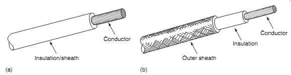
FIG. 1 Typical aircraft wires and cables: (a) single-walled, (b) twin-walled
Conductor Insulation/sheath (a) Conductor Insulation Outer sheath (b)
====
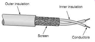
FIG. 2 Screened cable
Outer insulation; Inner insulation ; Screen; Conductors
=====
3.1 Wire size
Wire sizes used on aircraft are defined in accordance with the American Wire Gauge or Gage (AWG). For a given AWG, the wire will have a specified diameter and hence a known conductance (the reciprocal of resistance). Cable size relates to the conductor's diameter; the overall wire or cable diameter is there fore larger due to the insulation. The largest wire size is 0000 AWG; the smallest is 40 AWG.
Selection of wire size depends on the specified cur rent to be conducted. Larger diameter wires add weight, but offer less voltage drop for a given length and lower heating effect due to I 2 R losses.
Wire identification is printed on the outer surface of the sheath at intervals between 6 and 60 inches.
This includes the wire part number and manufacturers ' commercial and government entity ( CAGE) designation. The printing is either green or white (depending on the actual color of the wire).
Key point
Conductors must have low insulation resistance to minimize IR losses.
3.2 Performance requirements
Wires manufactured to MIL-W-M22759E have to demonstrate compliance with dimensions and construction, together with criteria to meet the following requirements:
- ease of removing the insulation
- ease of soldering
- dielectric testing
- flexibility
- elongation and tensile strength
- wicking
- high- and low-temperature testing
- flammability
- life cycle testing
- fluid immersion
- humidity
- smoke emission.
4. Shielding/screening
Shielded or screened wiring either prevents radiation from circuits switching high currents or protects susceptible circuits (see FIG. 2 ). The inner conductor carries the system current; the screen provides a low resistance path for coupling of electromagnetic fields. These fields are coupled into the shield and are dissipated to ground. (Further details on the theory of electromagnetic fields and shielding are given in Section 19.) Typical applications where shielding is used includes wiring installed near generators, ignition systems or contacts that are switching high currents. Shielded wires can be formed with single, twin, triple or quadruple cores. The classic example of screened wiring occurs with the Arinc 429 data bus which uses twisted screened pairs of cable to transmit digital data. This is being transmitted at either 12.5-14.5 (low speed) or 100 (high speed) k bits per second with a differential voltage of 10 V between the pair of wires. Examples of screened wire and cable specifications are found in M27500-22TG1T-14.
Key point: Wires and cables that carry high power, and/or high frequencies are shielded to prevent electromagnetic interference.
=======
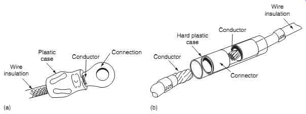
FIG. 3 Wire termination and splicing: (a) ring tongue terminal, (b) in-line
splice crimping
Wire insulation Plastic case Conductor Connection (a) Wire insulation Hard plastic case Conductor. Conductor; Connector 225; 225 (b)
=======
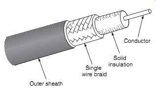
FIG. 4 Coaxial cable overview
Outer sheath Single wire braid Solid insulation; Conductor
=======
4.1 Crimps and splices
Individual wires and cables can be terminated or connected using crimps and splices. Care must be taken when stripping shielded cables; both the inner conductor and outer screen must be exposed in order to make the connection. The outer shield is formed into a pigtails and terminated with a crimp, or ring tongue terminal, see FIG. 3(a) . Alternatively, individual wires can be joined with an in-line splice , e.g. if a system is being modified with additional wiring, see FIG. 3(b) . Crimps and splices are formed over the exposed conductor and insulating material. The entire crimp or splice termination is then protected mechanically with a hard plastic case.
Test your understanding
Give some examples of wire/cable performance specifications.
4.2 Coaxial cables
A specialized version of the shielded wire is the coaxial cable. The inner conductor is solid or stranded; it can be plain copper or plated. The outer conductor forms a shield and is a single wire braid made from fine strands of copper or steel. The inner and outer conductors are separated by a solid insulation, forming a dielectric. The outer sheath or jacket provides protection against fluid contaminants. Coaxial cables are normally used to guide radio-frequency (RF) energy between antennas and receivers or transmitters. The inner conductor is shielded by the braiding from electric and magnetic fields; the conductor's own field is contained within the same shield. The net result is that fields from the inner and outer conductors cancel each other out. In most practical RF applications, coaxial cable radiation and susceptibility are virtually eliminated.
The typical construction of coaxial cable is shown in FIG. 4; the salient features are:
- inner conductor: silver plated copper
- solid insulation: (dielectric) foamed FEP
- single wire braid: (screen) tin plated copper
- outer insulation: (jacket) FEP.
(Further details on coaxial cables and antennas used in radio-frequency (RF) applications can be found in Aircraft Communications and Navigation Systems .) Other applications for coaxial cables include fuel quantity systems.
Coaxial cables are terminated with a bayonet or thread-nut couplings (BNCs and TNCs respectively). BNC has the advantage of a quick-release connection.
TNC performs well under vibration conditions since they have reduced axial movement. FIG. 5 gives an illustration of typical coaxial cable connectors and how they are fitted to the cable.
Test your understanding
What is the difference between shielded and coaxial cables?
======
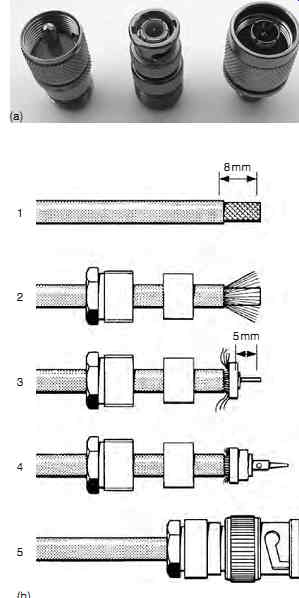
FIG. 5 Coaxial cable connectors: (a) typical end fittings, (b) terminating
the coax cable
====
5. Circuit protection
The current-carrying capacity of a wire or cable is determined by its length and cross sectional area; heat dissipation is determined by I 2 R losses. When the circuit or system is designed, the wire size is selected to safely carry this current. Wires and cable are subjected to abrasion during the normal service life of the aircraft; this can lead to the conductor being exposed. This exposure could lead to a low resistance path between the conductor and the airframe and/or an adjacent conductor. Faulty equipment, low resistance paths or overloading from additional circuits will cause the current to increase and this might exceed the current-carrying limit of the conductor. Heat will build up in the wire leading to fumes, smoke and ultimately fire. It is vital that we protect against this whilst allowing for transients; the methods used in aircraft are selected from the following devices:
- fuse
- circuit-breaker
- limiting resistor.
5.1 Fuses
Fuses are links of wire that are connected in series with the circuit. Their current-carrying capacity is predetermined and they will heat up and melt when this is exceeded, thereby interrupting and isolating the circuit. Materials used for the fusible link include lead, tin-bismuth alloy, copper or silver alloys.
Referring to FIG. 6(a) , the fuse wire is contained with a glass or ceramic casing (or cartridge) to pre vent any particles of hot metal escaping which could cause secondary damage. End-caps provide a connection for the fuse wire and make contact with the circuit wiring. Fuse holders consist of terminals and a panel clamp-nut.
=======
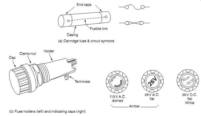
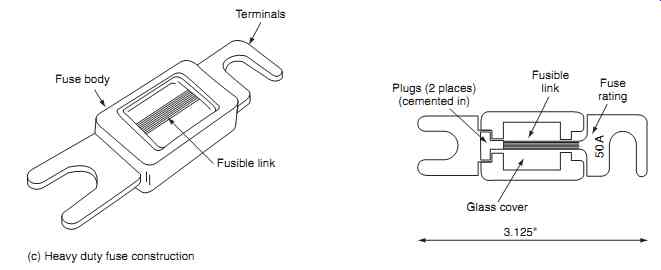
FIG. 6 Aircraft fuses: End caps Casing Fusible link (a) Cartridge fuse & circuit
symbols; Cap Clamp-nut Holder Terminals 115V A.C. domed 26V A.C. flat 26V D.C.
flat White Amber (b) Fuse holders (left) and indicating caps (right) Fuse
body Fusible link Terminals (c) Heavy duty fuse construction 50A Fusible
link Fuse rating Glass cover Plugs (2 places) (cemented in) 3.125"
=======
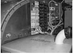
FIG. 7 Fuse clipped directly into a terminal board
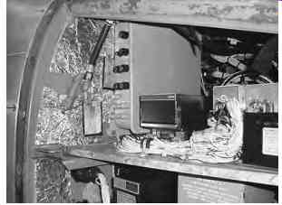
FIG. 8 Fuses located in a panel
Some fuse holders have an indication of the fuse condition, i.e. if the fuse has blown. The indicating cap is black with an integrated colored light.
When the fuse has blown, the cap illuminates; different colors indicate different power supply voltages.
Heavy-duty fuses (typically protecting circuits with up to 50 A current) are constructed with a ceramic body and terminals, see FIG. 6(c) . Fuses are either clipped into position on a terminal board, see FIG. 7 , or screwed into a panel, see FIG. 8.
Fuses are relatively low cost items, but they can only be used once. In some applications, the fuse material and physical construction is designed to have a time delay; the so-called slow-blow fuse, or current limiter . This is made from a copper alloy that has a higher melting point than lead/tin. It has a single strip of material waisted into a narrow cross-section to provide the fusing point. Heavy-duty fuses are used at power distribution points. They have multi-strands of parallel elements and are rated up to 500 A. This type of fuse is fitted with a packing medium to contain the debris following rupture. Materials used include quartz, magnesium oxide, kieselguhr or calcium carbonate (chalk).
Fuses have a rating that determines the maximum current it can carry without melting. The fuse will also have a minimum fusing current that is affected by ageing; a process that occurs when the fuse is operated at the minimum fuse rating for prolonged periods of time. Ambient temperature affects the cur rent rating and response time of a fuse. They must be located close to power source to minimize the length of unprotected wire; at the same time they have to be accessible for replacement. Spare fuses must be carried on the aircraft and be accessible to the flight crew. Typical requirements are to carry 50% of each rating as spares, e.g. if the aircraft is fitted with four 10 A and five 15 A fuses, then two 10 A and three 15 A fuses should be carried as spares.
Key maintenance points
1. Fuses can rupture, or 'blow ', when exposed to vibration and thermal cycling as well as during overload conditions.
2. Determine the reason that caused the fuse to blow before replacing.
3. Never assume that the blown fuse is to be replaced with the same rating; always check the aircraft documents.
5.2 Circuit-breakers
Circuit-breakers are electromechanical devices that interrupt and isolate a circuit in the event of excessive current. Unlike fuses, circuit-breakers can be reset (assuming that the fault condition has cleared). There are two circuit-breaker principles: electromagnetic and thermal.
An electromagnetic circuit-breaker is essentially a relay with current flowing through a coil; the resulting magnetic field attracts an armature mechanism. The current is normally a proportion of the main load current; this increases in proportion to the main load current. The armature mechanism is linked to a pair of contacts that carry the main load current. These contacts are opened when the current through the coil exceeds a certain limit.
Thermal -type circuit-breakers consist of a bimetallic thermal element, switch contacts and mechanical latch. The internal schematic of a thermal circuit breaker and its external features are illustrated in FIG. 9 . The thermal element is a bimetallic spring that heats up as current passes through it; this eventually distorts and trips the mechanism when the rated level is exceeded. The mechanism is linked to the main switch contacts, when the circuit-breaker 'trips ' the contacts open, thereby disconnecting power from the circuit. When the contacts open, a button is pushed out of the circuit-breaker. This button is used to manually reset the contacts; a white collar just below the button provides visual indication that the circuit-breaker is closed or tripped.
========
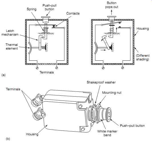
FIG. 9 Aircraft circuit-breakers (thermal type): (a) internal schematic
(closed and tripped), (b) external features
(a) Push-pull button’ Button pops out Spring Latch mechanism Thermal element Contacts Housing (Different shading) Terminals; Shakeproof washer Mounting nut Push-pull button White marker band Housing Terminals (b)
========
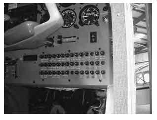
FIG. 10 Circuit-breaker panel
Some circuit-breakers use a large collar grip to identify specific systems. They can be locked open if required, e.g. if the system is installed but not certified for operation. As with fuses, the circuit-breaker should be located as close as possible to source of power; they are often arranged on the panels in groups.
Circuit-breakers can also be used to conveniently isolate circuits, e.g. during maintenance. Certain circuit-breakers are fitted with removable collars so that they can be readily identified. The circuit-breaker cur rent rating is engraved on the end of the button (see FIG. 10 ). Circuit-breakers can be single- or multi pole devices (poles are defined as the number of links that a switching device contains). Multi-pole devices are used in three-phase AC circuits.
Various configurations of circuit-breaker are installed on aircraft, including:
1. automatic reset
2. automatic trip/push to reset
3. switch types
4. trip free.
The circuit symbols for each of these types is illustrated in FIG. 11 . Trip-free circuit-breaker contacts cannot be closed whilst a fault exists. This is the preferred type of circuit-breaker on aircraft, especially on new installations.
=======
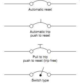
FIG. 11 Circuit-breaker symbols/type
Automatic reset; Automatic trip push to reset; Pull to trip push to reset (trip free); Switch type
=======
5.3 Limiting resistors
These are used to limit current surges, primarily in DC circuits, where the initial current surge is large. When these circuits are switched they create large current flows that can be harmful to other components and reduce the power supply voltage for a period of time (determined by the time constants of the circuit). Limiting resistors are connected in series with such circuits and then automatically shorted out once the circuit current has stabilized.
Typical applications of limiting resistors are found in engine starting circuits and voltage regulators.
Limiting resistors are also used in fire extinguishing systems. Fire extinguishers are activated by applying direct current (DC) through current-limiting resistors to the associated squib; this ruptures a disc that allows extinguishing agent to be expelled under pressure. The limiting resistors pre vent inadvertent operation of the squib. In electronics, limiting resistors are used to protect devices such as diodes.
6. Multiple choice questions
1. Wires and cables that carry high power and/or high frequencies are shielded to prevent:
(a) the wire or cable being the cause of electromagnetic interference
(b) the wire or cable being affected by electromagnetic interference
(c) wet arc tracking.
2. Two or more separate wires within the same insulation and protective sheath is referred to as a:
(a) screened wire
(b) coaxial cable
(c) cable.
3. Fuses have a rating that determines the:
(a) maximum current it can carry without opening
(b) minimum current it can carry without opening
(c) time taken for the fuse to rupture.
4. Conductors must have low insulation resistance to minimize:
(a) current surges
(b) electromagnetic interference
(c) IR losses.
5. The combined effects of insulation damage and
fluid contamination gives rise to:
(a) electromagnetic interference
(b) wet arc tracking
(c) current surges
6. For a given AWG, the wire will have a specified:
(a) diameter and hence a known conductance
(b) length
(c) screening.
7. Coaxial cables are normally used for:
(a) digital signals
(b) motors and generators
(c) radio-frequency (RF) signals.
8. Trip-free circuit-breaker contacts:
(a) can always be closed whilst a fault exists
(b) cannot be closed whilst a fault exists
(c) are only used during maintenance.
9. Limiting resistors are connected:
(a) momentarily in series
(b) momentarily in parallel
(c) permanently in series.
10. The white collar just below a circuit-breaker button provides visual indication of the:
(a) circuit-breaker trip current
(b) system being protected
(c) circuit-breaker being closed or tripped.