AMAZON multi-meters discounts AMAZON oscilloscope discounts
(cont. from part 1)
5. Fluid pressure transducers
There are two basic methods used to measure fluid pressure: the Bourdon tube or a capsule. Typical fluid pressures being measured on the aircraft include hydraulic oil and fuel.
5.1 Bourdon tube
The Bourdon tube was invented by Eugène Bourdon (1808-84), a French watchmaker and engineer. The pressure-sensing element is a tube with either a flat or elliptical section; it is formed as a spiral or curve, see FIG. 15. One end of the tube is sealed and connected to a pointer mechanism, the open end is connected to the fluid system via a pipe.
As the applied pressure from the fluid system increases, the tube will tend to straighten out, while a reduced pressure will cause the tube to return to its original shape. This movement is transferred via the gear mechanism to move a pointer. The pointer moves across a scale thereby providing a direct reading of pressure. Materials used for the tube are selected for the pressure range being measured; these include phosphor bronze (0-1000 psi) and beryllium copper (0-10,000 psi). The Bourdon tube principle can also be used to remotely measure pressure, see
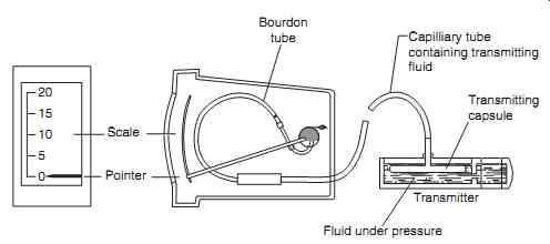
FIG. 16
5.2 Pressure capsule
The other method used for measuring fluid pressure is with a capsule , see FIG. 17 . As pressure is applied by the fluid, the capsule expands. This moves an iron bobbin within the envelope of two inductor coils.
These coils are part of an AC ratiometer system as illustrated in FIG. 18. The linear shaded pole motors are single-phase induction motors. An unbalance of currents in the inductor coil circuits is caused by displacement of the cores within the coil. Current then flows in one of two directions into the motor circuits. The rotors of the motor are the aluminum discs attached to a shaft. This arrangement produces a low starting torque to produce a responsive indicating system.
An alternative arrangement is to connect the iron bobbin to a micro-switch to provide indications of low/high pressure. The advantage of this capsule sys tem is that pressure pipes do not need to be run all the way up to the cockpit indicators.
=======
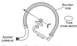
FIG. 15 Bourdon tube principles
Bourdon tube; Tube cross section; Applied pressure
=======
FIG. 16 Bourdon tube/remote pressure sensing
Scale; Pointer; Bourdon tube; Capillary tube containing transmitting fluid; Transmitting capsule; Transmitter; Fluid under pressure
=======
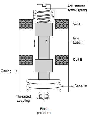
FIG. 17 Pressure transducer
Adjustment screw/spring; Iron bobbin; Coil B; Capsule; Fluid pressure; Threaded coupling; Casing; Coil A
=======
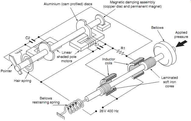
FIG. 18 AC ratiometer
Aluminum (cam profiled) discs; Magnetic damping assembly (copper disc and permanent magnet); Bellows; Laminated soft iron cores; Inductor coils; Linear shaded pole motors; Hair spring; Pointer; Bellows restraining spring; 26V 400 Hz; Applied pressure; R1, C1, C2
========
6. Temperature transducers
Aircraft use a variety of temperature transducers, or sensing devices, ranging from the simple bi-metallic strip or thermostat through to thermistors and thermocouples. The type of sensor used depends on the application and takes into account:
- temperature range
- accuracy requirements
- type of output required
- cost
6.1 Bi-metallic strip
A bi-metallic strip converts temperature changes into mechanical displacement as an on/off measurement.
The device consists of two strips of different metals with different coefficients of thermal expansion. The strips or elements are joined together by rivets, by brazing or by welding (see FIG. 19 ).
Differential expansion causes the element to bend one way when heated, and in the opposite direction when cooled below its nominal temperature. The metal with the higher coefficient of expansion is on the outer side of the curve whilst the element is heated and on the inner side when cooled. The element can be formed as a switch contact, called a thermostat, to open or close a circuit when temperature limits are exceeded.
Alternatively the element is formed in a spiral shape so that temperature changes cause a shaft to rotate; the typical application for this is an outside air temperature indicator, see FIG. 20 (a) .The sensing portion of the indicator projects through windscreen ( FIG. 20(b) ) into the ambient air.
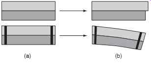
FIG. 19 Bi-metallic strip principles: (a) before heating, (b) after heating.
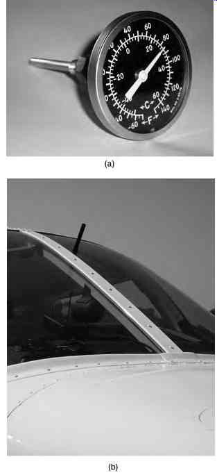
FIG. 20 Bi-metallic strip application: (a) outside air temperature indicator,
(b) outside air temperature (sensor projecting through windscreen)
6.2 Thermistors
A thermistor is a type of resistor ( thermal resistor ) used to measure temperature; the principle is based on the known relationship between resistance and temperature. The thermistor product used on aircraft is the resistance temperature device (RTD), also known as a resistance thermometer detector, or temperature bulb. Figure. 9.21 illustrates some features of an RTD. A length of very small diameter wire is wound on a bobbin to form resistance windings. The bobbin is contained within a stainless steel body to protect the windings against contaminants. Each end of the windings is soldered onto pins that are formed into an electrical connector; this is welded to the flange, resulting in a hermetically sealed unit.
The principles of this temperature-measuring device is based on measuring the change of resistance of a metal element and interpreting this as temperature. Metal elements have a positive temperature coefficient ; certain metals, e.g. nickel and platinum, have a very stable and linear relationship between resistance and temperature, see FIG. 22 . Nickel is less accurate than platinum, and is non-linear below 200ºC, but has lower cost.
RTDs are typically used within a DC ratiometer circuit , see FIG. 23 . A permanent magnet is attached to the pointer of the measuring instrument. When the RTD resistance is equal to the fixed resistor value, the current in each leg is equal and the pointer takes up the center position. With a change in temperature, the RTD resistance value changes and the current through each leg is not equal, thereby causing the pointer to take up a new position. The position of the pointer is in proportion to the ratio of currents in each leg of the network.
Alternatively they are used in a Wheatstone bridge circuit, named after Sir Charles Wheatstone (1802-75), a British scientist. The circuit was actually invented by Samuel Hunter Christie (1784-1865), a British scientist and mathematician; Sir Charles Wheatstone further developed the circuit. It was used to measure an unknown value of resistance by balancing two legs of a bridge circuit, one leg of which includes the unknown value.
============
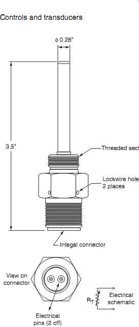
FIG. 21 Resistance temperature device (RTD) features
3.5" Integral connector; Threaded section; Lockwire holes 2 places; View on connector RT; Electrical schematic; Electrical pins (2 off)
=============
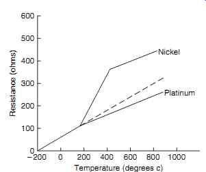
FIG. 22 RTD temperature and resistance chart
===========
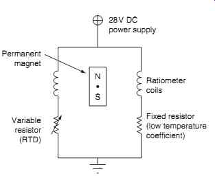
FIG. 23 DC ratiometer
N S 28V; DC power supply; Ratiometer coils; Fixed resistor (low temperature coefficient); Variable resistor (RTD); Permanent magnet
==============
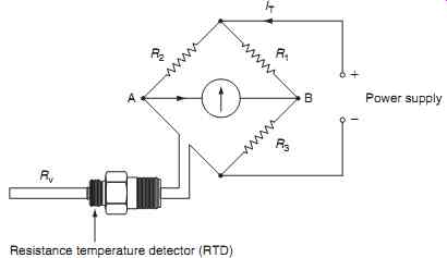
FIG. 24 Wheatstone bridge
Resistance temperature detector (RTD)
==================
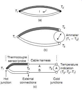
FIG. 25 Thermocouple principles: (a)
the Seebeck effect, (b) simple thermocouple circuit, (c) practical thermocouple circuit
Temperature indication; (T3_T2_T1) B; Cable harness; Cold junctions; External connections; Hot junction Thermocouple sensor/probe (c)
==================
This circuit developed by Wheatstone is based on Ohm's and Kirchhoff 's laws. It is typically used as an accurate method to overcome the effect of power supply variations. Referring to FIG. 24 , resistors R1 , R2 , and R3 have fixed values; the RTD is the variable resistor in the bridge network. Current IT splits from the power supply splits into I1 and I2 . Depending on temperature, if the RTD value equals R1 then I1 _ I2 and VA _ VB so I3 is zero and the meter pointer has a zero deflection. A change in value of RTD (as a result of temperature) means that VA is no longer equal to VB . Current I3 increases and the meter pointer is deflected, thereby indicating a change in temperature.
For a given temperature, if the power supply voltage changes, then IT will change in proportion, however I1 and I2 will be the same irrespective of the change in voltage. Thus, any variation in power supply does not affect the temperature reading. ( R1 and R2 are used to prevent a short circuit if the RTD value is zero ohms.)
6.3 Thermocouples
The thermocouple principle is based on a thermo electric effect; this is a generic expression used for temperature-dependent electrical properties of matter.
Thermocouples use the potential difference that results from the difference in temperature between two junctions of dissimilar metals. This thermoelectric potential difference is called the Seebeck effect , named after the German physicist Thomas Seebeck (1770- 1831). Two metal conductors made out of different materials are welded at each end to form junctions , see FIG. 25(a). The thermocouple junction is housed with a stainless steel tube to provide mechanical support; the wires are terminated as a junction in the thermocouple head.
When a temperature gradient between each junction is created, electrons will diffuse from the higher temperature junction to the colder junction. This creates an electric field within the conductors, which causes a current to flow, and an electromotive force (e.m.f.) to be generated. In a simple circuit, FIG. 25(b) , the hot junction is exposed to an unknown temperature ( T2 ). The cold junction is contained with the indicator (measuring current); this is at a known temperature (T1 ). The practical thermocouple circuit is shown in FIG. 25(c) . The hot junction is located in the thermocouple head, or probe. Connecting cables back to the meter are either built into the probe as flying leads, or they are attached onto external connectors.
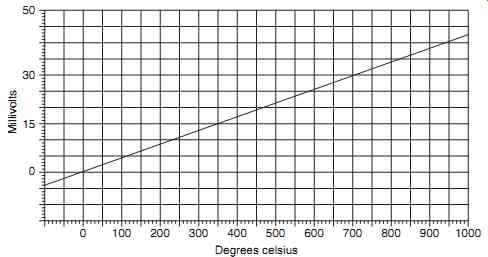
FIG. 26 Thermocouple output (voltage/temperature) --- Degrees Celsius;
Millivolts
Key maintenance point
It is important that the materials used in the harness are matched to the thermocouple type, otherwise additional junctions would be formed by dissimilar materials causing unwanted junctions and additional temperature gradients.
The relationship between the temperature gradient and EMF is linear; a typical thermocouple will generate approximately 4 mV per 100ºC of temperature difference, see FIG. 26 .
There are many different combinations of materials used for the two thermocouple wires; the choice of materials depends mainly on the operational range of temperatures to be measured. Typical materials and upper temperatures are:
- nickel-chrome/nickel-aluminum alloys * (1000ºC)
- iron/constantan (400ºC)
- copper/constantan (300ºC)
Another term associated with thermoelectric principles is the Peltier effect, named after Jean Peltier (1785- 1845). This is the opposite of the Seebeck effect; by applying a potential difference between two junctions, the temperature of the materials can be controlled.
Test your understanding
Explain the basic principles of bi-metallic switches, RTDs and thermocouples.
Key point
In an ideal thermocouple circuit, the cold junction should be maintained at constant temperature to ensure that the temperature difference is being accurately measured.
7. Strain transducers
Strain is defined as the deformation of a material caused by the action of stress . Defined as force per unit area, stress is a measure of the intensity of internal forces acting within a body. Strain is determined by a change that takes place between two material states, from the initial state to the final state. The physical displacement of two points in this material between these two states is used to express the numerical value of strain. A strain gauge is a device used to measure the deformation of a material when forces act upon it; the principles of a metallic foil strain gauge are illustrated in FIG. 27. Edward E. Simmons, an electrical engineer from the USA, developed the principle of the metallic foil type in 1938.
*These are often referred to as chromel and alumel; trade names of the Hoskins Manufacturing Company. Further details of thermocouple applications are given in Section 10 (engine systems).
=============
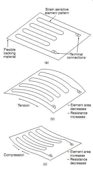
FIG. 27 Strain gauge principles (a) no strain, (b) tension, (c) compression
(a) Strain sensitive element pattern Terminal connections Flexible backing
material (b)
- Element area decreases
- Resistance increases
Tension
- Element area increases
- Resistance decreases
Compression
=============
The piezo-resistive strain gauge is based on the material's change of electrical resistance when subjected to mechanical stress. This effect was first discovered in 1856 by Lord Kelvin (1824-1907), a British mathematician, physicist and engineer. The principle was subsequently developed with silicon and germanium semiconductors during the 1950s.
Strain gauges have a number of applications on air craft, e.g. the measurement of torque in an engine drive shaft. The metallic foil gauge is attached to the surface of the shaft, either by a suitable adhesive (metallic foil strain gauge) or it can be fabricated as an integral section of the tube surface. As the shaft is twisted by engine power, the strain gauge is deformed, causing its electrical resistance to change. Applications of this principle are discussed further in Section 10 (engine systems).
8. Rotary position transducers
There are many examples on an aircraft that require the measure of angular position; for example the position of shafts that drive control surfaces. By measuring the angle of the shaft mechanism that drives a control surface, and indication can be provided to the flight crew, or used in a computer. The type of power supply available (DC or AC) determines the main types of synchro systems used on aircraft.
8.1 DC synchro
The DC synchro consists of a transmitter and receiver as illustrated in FIG. 28. The transmitter is wire-wound circular resistance with three pick offs. The input shaft (of the device being monitored) is attached to the two contacts that slide across the resistance windings. These contacts are insulated from each other and connected to the power supply. The receiver contains a permanent magnet attached to a shaft; the magnet is positioned within three stator windings. DC synchros are known by various trade names including Selsyn and Desyn.
With the two contacts in the positions shown in Fig. 28 , the power supply current enters the resistor at point A, current flows into the top coil (A) of the receiver and splits into the lower coils (B and C). This current sets up three magnetic fields around each of the three coils; the permanent magnet in the receiver takes up a position that aligns with the resulting magnetic field. A pointer attached to the receiver shaft moves to a position inside the indicator. When the input shaft of the transmitter is rotated, the contacts move to a new position. This alters the balance of currents through the resistance windings resulting in a change of currents in the receiver coils. The resulting magnetic flux rotates and the permanent magnet aligns to the new direction, moving the pointer to a different position.
Key maintenance point
The DC synchro suffers from contact wear on the resistance windings; this can lead to spurious operation.
============
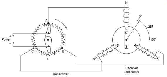
FIG. 28 DC synchro (electrical schematic)
============
8.2 AC torque synchro
The AC torque synchro also consists of a transmitter and receiver. These are similar in form; stator and rotor windings are illustrated in FIG. 29 . Interconnections are shown in FIG. 30 . The rotors consist of an iron core, single winding, slip-rings and brushes. Stators consist of three sets of windings each at 120 degrees to each other. The rotors of the transmitter and receiver are supplied from same power supply (normally 26 V AC); this alternating supply flows through both the rotor coils via slip-rings . Current flowing through the transmitter's rotor creates an alternating magnetic field; this induces currents into each of its stator windings.
Key point
Torque synchros have the advantage of no contact wear on resistance windings.
Referring to FIG. 31 , the current from each of the stators flows out of the transmitter and into the receiver where it creates magnetic fields in each of the stator windings. The receiver's rotor will be aligned in angular position with the transmitter's rotor. Fig. 31(a) shows the system in correspondence. When the transmitter rotor is moved, this unbalances the induced voltages in the receiver until the receiver's rotor is aligned with the resulting magnetic field.
The system is then out of correspondence as shown in FIG. 31(b) . When the rotor of the receiver aligns itself with the field again, FIG. 31(c), the system is back in correspondence.
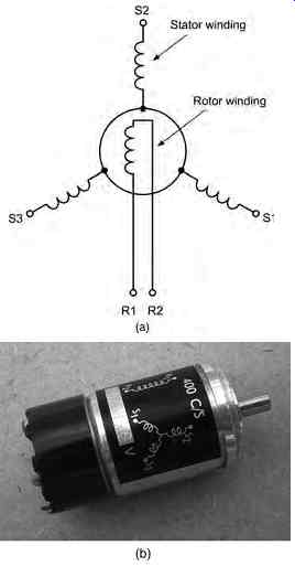
FIG. 29 AC torque synchro system: (a) transmitter/receiver schematic,
(b) transmitter/ receiver hardware.
Key point
Torque synchros are sometimes referred to by the trade name of Autosyn.
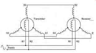
FIG. 30 AC torque synchro system schematic
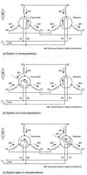
FIG. 31 AC torque synchro system operation
===========
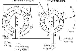
FIG. 32 AC Magnesyn synchro
Permanent magnet Soft iron core 1
Up Down Toroidal winding Indicating magnesyn; Transmitting magnesyn 26 V 400 Hz Power supply
===========
8.3 Magnesyn
An alternative AC synchro is known by the trade name of Magnesyn . The transmitter and receiver are similar in construction; see FIG. 32 . The rotors are permanent magnets, the stators are soft iron cores with toroidal windings. The transmitter rotor's permanent magnetic field is superimposed onto the stator field (generated from the power supply).
When the input shaft is rotated to a given position, the resulting magnetic field rotates and this causes the receiver's rotor shaft to take up the same position as the input shaft.
9 .QUIZ--Multiple choice questions
1. The number of circuits that can be linked by a single switch operation is called the:
(a) pole
(b) throw
(c) NO/NC contacts
2. The bi-metallic temperature sensor consists of:
(a) two strips of metal with different coefficients of thermal expansion
(b) two strips of metal with the same coefficients of thermal expansion
(c) two wires welded into a junction.
3. When a foil strain gauge is deformed, this causes:
(a) an electromotive force (EMF) to be generated
(b) its electrical resistance to change
(c) different coefficients of thermal expansion.
4. Metal elements used in RTDs have a temperature coefficient that is:
(a) negative, temperature increases cause an increase in resistance
(b) positive, temperature decreases cause an increase in resistance
(c) positive, temperature increases cause an increase in resistance.
5. The rotors of an torque synchro transmitter and receiver are supplied from:
(a) the same power supply (normally 26 V AC)
(b) different power supplies (normally 26 V AC)
(c) the same power supply (normally 26 V DC).
6. The thermocouple principle is based on the Seebeck effect; when heat is applied:
(a) a change of resistance is measured
(b) this causes the element to bend
(c) an electromotive force (e.m.f.) is generated.
7. A rheostat performs the same function as a:
(a) resistance temperature detector
(b) potentiometer
(c) Wheatstone bridge.
8. The solenoid is a type of transducer that converts:
(a) electrical energy into linear motion
(b) linear motion into electrical energy
(c) electrical energy into thermal energy.
9. Proximity switches perform the same function as:
(a) micro-switches
(b) relays
(c) toggle switches.
10. The linear variable differential transformer (LVDT) is used for measuring:
(a) small rotary displacements
(b) variable resistance
(c) small linear displacements.
11. Referring to FIG. 33, these control devices are:
(a) toggle switches
(b) micro switches
(c) rocker switches.
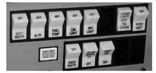
FIG. 33
12. Referring to FIG. 34, this device is a:
(a) toggle switch
(b) micro switch
(c) changeover relay
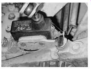
FIG. 34
13. Referring to FIG. 35, this circuit is called a:
(a) wheatstone bridge
(b) thermocouple bridge
(c) ratiometer
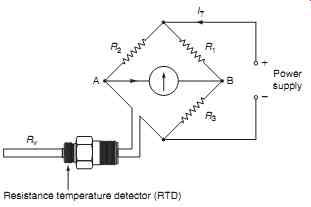
FIG. 35: Resistance temperature detector (RTD)
15. Referring to FIG. 37, this chart shows the output of a:
(a) RTD
(b) thermocouple
(c) strain gauge
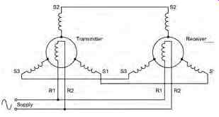
FIG. 36
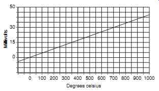
FIG. 37
14. Referring to FIG. 36, this schematic is for a:
(a) AC magnesyn synchro
(b) AC torque synchro
(c) DC synchro