AMAZON multi-meters discounts AMAZON oscilloscope discounts
The aircraft engine is installed with many systems requiring electrical power. The predominant requirement (in terms of current consumption) is for the starting system. General aviation aircraft use electrical starter motors for both piston and gas turbine engines; larger transport aircraft use an air-start sys tem (controlled electrically) derived from ground support equipment or by air cross-fed from another engine. Electrical starting systems on piston and gas turbine engines are very different. The trend towards the all-electric aircraft will see more aircraft types using electrical starting methods. The engine also requires electrical power for the ignition system. Once again, the needs of piston and gas turbine engines are quite different. Although starting and ignition systems are described in this section as separate systems, they are both required on a co-ordinated basis, i.e. a means to rotate the engine and ignite the air/fuel mixture.
Electrical and electronic requirements for engines also include the variety of indicating systems required to operate and manage the engine. These indicating systems include (but are not limited to) the measurement and indication of: rotational speed, thrust, torque, temperature, fuel flow and oil pressure.
Indications can be provided by individual indicators or by electronic displays. This section describes engine starting, ignition and indicating system for both piston and gas turbine engines.
1. Starting and ignition
1.1 Piston engines
The original way of starting piston (internal combustion) engines was by ' swinging ' the propeller; this involves using the propeller as a lever to turn the engine shaft. The method in widespread use on most engines now is a starter motor powered by the aircraft battery. Basic electrical starting systems comprise a series or compound wound motor with engaging mechanism.
The simplest method of physically connecting the motor to the reciprocating engine is via a pinion on the motor that engages with a gear ring attached to the crankshaft; this mechanism disconnects after the engine has started. This pinion and gear ring provides a gear ratio in the order of 100:1 to turn the engine at sufficient speed to overcome compression and bearing friction.
Referring to FIG. 1 , the battery master switch is selected on; this energizes the battery relay and power is applied to the busbar and starter relay. When the starter switch is closed, this energizes the starter relay and applies power to the starter motor. As soon as the engine fires and starts, the starter switch is released and power is removed from the motor; this opens the starter relay contacts.
1.2 Twin-engine (piston) starting system
The twin-piston engine aircraft is started in a similar way to the single engine. Referring to FIG. 2, power is applied from the battery to the battery relays.
When the battery master switch is turned on, power is available at both the starter relay. Power is also made available at the busbar and the starter circuit breaker is fed to the dual starter switch. Each engine is started by its own set of contacts. When an engine has been started the switch is released and the spring-loaded contacts return it to the center-off position.
1.2.1 Magneto ignition (high-tension type)
Ignition energy for piston engines is generated from a magneto ; this provides pulses of electrical power via a distributor to spark plugs in each of the engine cylinders. The magneto operates on the principle of electromagnet induction (FIG. 3); it is a combined four-pole permanent magnet generator and autotransformer and can be used where there is no aircraft battery. The engine drives the input shaft of the magneto rotor via a gearbox; the relative movement of trans former windings and the poles of a permanent mag net can be arranged in one of three ways:
1. The transformer coils are on the shaft and the magnet is fixed to the housing (rotating armature type);
2. The permanent magnet is rotated by the shaft within stationary coils of the transformer (rotating magnet type);
3. A soft iron inductor is rotated between the permanent magnet and transformer windings (polar inductor type).
For every revolution of the shaft, a cam opens the contact breaker, interrupting the primary current; this causes the electromagnetic field in the primary coil winding to collapse. As the field collapses there is a voltage generated across the primary coil. A capacitor connected across the contacts discharges when the breaker contacts are closed and charges when they open. When the capacitor discharges, a high current flows through the primary coil, inducing high secondary voltages. The capacitor also prevents arcing across the breaker contacts, and determines the volt age across the primary coil thereby controlling the rate at which the electrical energy dissipates through the primary coil. The magneto's output is directed to the spark plugs via a distributor. The distributor shaft is connected via gears to the magneto shaft; this ensures that energy is applied to the spark plugs with the correct timing.
In the aircraft engine, each cylinder normally has two spark plugs, each driven from a separate magneto. This arrangement provides redundancy in the event of failure of one of the magnetos. Two sparks per cylinder also provides a more complete and efficient burn of the fuel/air mixture. The magneto's simplicity and self-contained design provides reliability as well as light weight. An on/off switch controls the system; in the off position, the primary winding is connected to ground, and this prevents current from being induced in the primary windings.
========
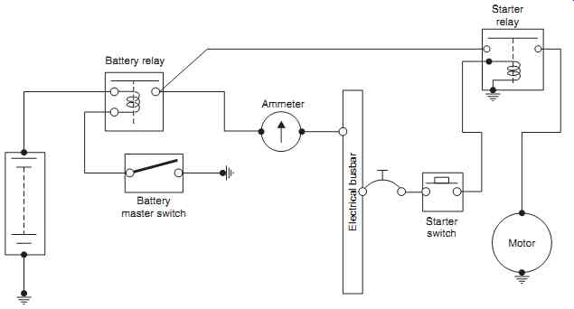
FIG. 1 Electrical starting system
Battery relay; Ammeter; Battery master switch; Starter switch; Motor; Starter relay; Electrical busbar
========
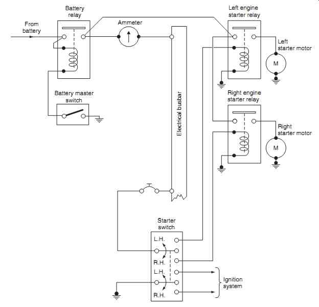
FIG. 2 Twin-piston engine aircraft starting
Left starter motor; Right starter motor; Starter switch; Battery relay; Ammeter; From battery; Battery master switch; Left engine starter relay; Right engine starter relay; Ignition system; Electrical busbar
==========
1.2.2 Magneto ignition (low-tension type)
A larger piston engine has more cylinders and is designed to operate at higher altitudes. Decreased atmospheric pressure means that the high-tension magneto system is prone to electrical insulation breakdown in the distribution cables. The low-tension magneto system is based on the polar inductor method. The output from the magneto is a low volt age; this is increased to a high voltage by secondary transformers located near the plugs. This reduces the length of high-tension cable and reduces the risk of insulation breakdown in the distribution cables.
Brushes and commutators form the low-tension magneto distributor. Ignition cables carry the high energy from the magneto to the plugs. The single core of stranded conductors is insulated by a substantial thickness of material.
========
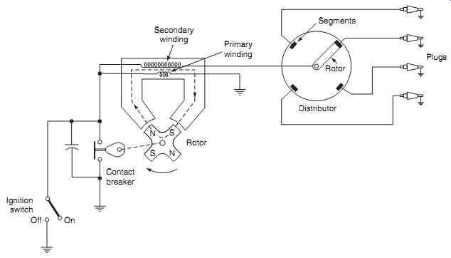
FIG. 3 Magneto ignition principles
On; Off; Distributor; Segments; Rotor; Plugs; Contact breaker; Primary winding; Secondary winding; Rotor; Ignition switch
========
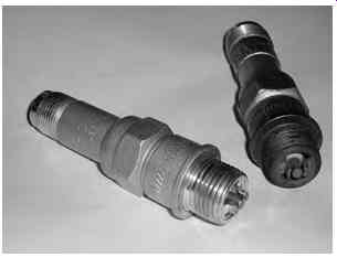
FIG. 4 Spark plugs (new and used)
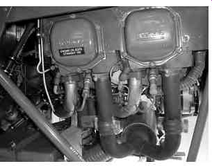
FIG. 5 Spark plug installation
1.2.3 Spark plugs
These conduct the high-energy output from the magneto across an air gap, see FIG. 4 . The fuel/air mixture across the gap is an insulator; as the voltage from the magneto increases, it alters the structure of the fuel/air mixture between the electrodes. Once the voltage exceeds the dielectric strength of the fuel/air mixture, it becomes ionized. The ionized fuel/air mix ture then becomes a conductor and allows electrons to flow across the gap. When the electrons flow across the gap, this raises the local temperature to approximately 60,000 K. The electrical energy is discharged as heat and light across the air gap, thereby appearing as a spark with an audible ' clicking ' sound. This energy ignites the fuel mixture in the cylinder.
The plug is fitted into the cylinder head's combustion chamber and is therefore exposed to high pressures and temperatures; plugs have to operate with minimal deterioration over long periods of time in this harsh environment. The outer shell of the plug is made from high tensile steel with close tolerance threads to locate the plug in the cylinder head; a cop per crush-washer completes the seal against high gas pressures. The outer shell is connected electrically to the cylinder head through its body. The center electrode carries the high tension energy to the spark gap; this is formed from a material that is resistant to the repetitive arcing, typically nickel, platinum or iridium. An insulator separates the inner and outer sections of the plug, typical materials include mica, ceramic, aluminum oxide ceramic. Examples of spark plug installations, together with ignition cables, are shown in FIG. 5 .
Key point
Two spark plugs per cylinder provides redundancy in the event of magneto failure and an efficient burn of the fuel/air mixture.
1.3 Turbine engine starting
Starting a turbine engine requires a higher-duty motor compared with piston engines; the motor has to overcome higher inertia and needs to achieve higher cranking speeds. The general features of a gas turbine engine are illustrated in FIG. 6 . Air is com pressed through a multi-stage system before entering the combustion chamber where it is mixed with fuel and ignited. The expanding exhaust gases are then directed through a turbine to produce thrust. The turbine also turns shafts to drive the compressor stages.
The starter motor has to overcome the inertia of the compressor; a large volume of air has to be drawn through engine and then accelerated and compressed until the engine's self-sustaining speed is reached.
Self-sustaining speed is when sufficient energy is being developed by the engine to provide continuous operation without the starting device. When the turbine engine is driving a propeller (commonly called a turboprop) the starter has to overcome the additional inertia of the propeller (helicopter engines are normally connected to the rotor via a clutch).
A typical turbine engine starter circuit is illustrated in FIG. 7 . Current from the busbar is connected to the coil of a starter relay via a push-button switch. This makes a circuit to a timer switch and starter motor via a limiting resistor. (The resistor limits excessive currents that would otherwise occur in overcoming the initial torque of the motor.) Once the motor speed has reached its nominal operating speed , its starting torque reduces and the timer switch operates contacts for the shorting relay. With the relay energized, current from the busbar is switched directly into the motor, i.e. bypassing the resistor.
Ignition is switched on when self-sustaining speed is reached; power to the motor is removed.
===============
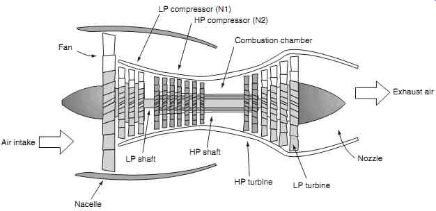
FIG. 6 Gas turbine engine features
LP compressor (N1); HP compressor (N2); Combustion chamber; Fan; Nozzle LP turbine HP turbine; HP shaft; Exhaust air; LP shaft; Nacelle; Air intake
===============
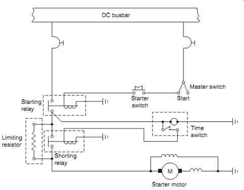
FIG. 7 Turbine engine starter circuit
DC busbar; Master switch; Starter switch; Start; Time switch; Starter motor; M; Shorting relay; Limiting resistor; Starting relay
==============
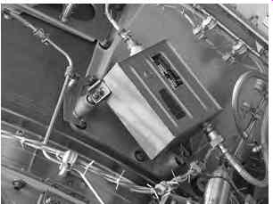
FIG. 8 Ignition unit installation
Key point
The initial current through the turbine engine starter motor is in the order of 1000-1500 A, hence the need for a limiting resistor and timing circuit.
Direct-cranking electrical starting systems are similar to those used on piston engines. A typical 28 V DC four-pole motor produces 15-20 lb/ft of torque.
The output shaft is clutched into a gear mechanism via the accessory gearbox. Typical duty cycles for motors in small- to medium-size engine requires speeds of 3800 r.p.m. for up to 90 seconds with current peaking at 1000 A. The motor must transmit sufficient torque to the engine's rotating assembly to provide smooth acceleration from rest up to the self-sustaining speed; at this point, the motor is disengaged.
Some aircraft are installed with a combined starter-generator. This involves a permanent coupling of the starter-generator shaft to the engine via a gearbox drive. The dual-purpose machine is compound-wound and the field is connected via a changeover relay. During engine start it acts like a conventional motor until the engine is up to speed.
The changeover relay then automatically connects the field windings to a voltage regulator and it becomes a conventional generator. The starter-generator system has reduced weight and component parts compared with having a separate starter motor and generator, thereby reducing overall operating costs.
1.3.1 High-energy ignition unit (HEIU)
High-energy ignition is required for starting gas turbine engines; a dual system is normally installed for the main engines. The system comprises two HEIUs and two igniter plugs per engine. A typical HEIU installed on an engine is shown in FIG. Turbine ignition systems are switched off after the engine has reached self-sustaining speed; the system is used as a precaution during certain flight conditions e.g. icing, rain or snow. In-flight start uses the wind-milling effect of the engine within the specified flight envelope of air speed and altitude. High voltages are required for the igniter plugs to accommodate the variations in atomized fuel over the range of atmospheric conditions. Electrical energy is stored in the HEIU and then dissipated across the igniter plug.
Key maintenance point
The very high voltage output from an HEIU is potentially lethal. The HEIU can remain charged for several minutes; always refer to the maintenance manual for operating procedures.
1.3.2 Igniter plugs
Referring to FIG. 9, the end of the igniter plug is formed with the outer casing insulated from the center electrode. The end of the igniter is coated with a semi-conductive ceramic material. The output from the HEIU heats the surface of the ceramic material and lowers its resistance. This creates a high-intensity flashover from the center electrode to the outer casing. (Note this is a surface discharge, not a spark across an air gap.)
================
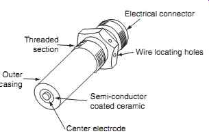
FIG. 9 Igniter plug features
Electrical connector; Threaded section; Outer casing; Center electrode; Semi-conductor coated ceramic; Wire locating holes
================
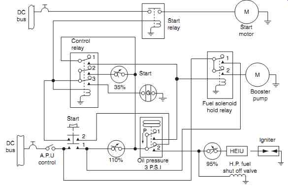
FIG. 10 Auxiliary power unit (APU) start and ignition
DC bus; DC bus; Start relay; Start; A.P.U control; 2 1 Start motor; Start; Control relay; 1 2 3 35% 110%; Oil pressure; 3 P.S.I Fuel solenoid hold relay; Booster pump; Igniter; HEIU H.P. fuel shut off valve 95%
================
1.4 Auxiliary power unit (APU) start and ignition
The APU on large transport aircraft is started electrically; air is then bled into the air distribution sys tem for the main engines. The APU starter motor is engaged and disengaged automatically as part of the starting system. Referring to FIG. 10, a centrifugal switch connected to the APU shaft controls the start sequence via three sets of contacts that operate at 35%, 95% and 110% of maximum speed. An oil pressure switch ensures that the system cannot start until the lubrication oil pump builds up sufficient pressure.
With the system circuit breaker closed, and the start switch selected, the start and control relays are supplied via the closed 110% switch contacts; the starter motor is now connected to the electrical supply via the start relay. The starting sequence is confirmed via a green annunciator light on the control panel; the light is connected to the power supply via contacts on the control relay. The fuel solenoid holding relay (FSHR) is operated via the control relay, and the 35% switch contacts; the low-pressure (LP) fuel pump motor is connected to the power supply via the FHSR. The start switch is now released; the starter circuits are maintained via the FHSR, 100/35% switch contacts and control relay. When the oil lube pump builds up sufficient pressure, this closes a switch that provides a retaining supply for the FSHR. The high pressure fuel shut-off valve is then energized open (allowing fuel to be delivered under pressure into the APU) and the ignition system is supplied via the 95% contacts. The APU continues to accelerate; at 35% engine speed, the start and control relays open; the starter motor is disengaged, and the 'start' light is switched off. At 95% of maximum speed, the contacts open and the ignition is switched off. The APU start sequence is now completed, and the engine runs constantly at 100% r.p.m. (There is no throttle control on the APU.)
The APU can be shut down either manually (by selecting the APU to off) or automatically. Loss of oil pressure at any time will automatically shut the APU down. An overspeed condition (sensed by the 110% switch opening its contacts) will de-energize the fuel solenoid holding relay, close the high-pressure fuel shut-off valve and remove power from the low pressure booster pump.
1.5 Main engine start
The main engines are normally started via air-driven motors; there are three sources of air for starting the main engines:
- APU
- ground air supply cart
- another engine
A typical air distribution system is illustrated in FIG. 11. Valves, controlled either manually or automatically, are operated by motors. With the APU started and running at normal speed, a switch on the start control panel opens the APU bleed valve. Air is directed through the isolation valve and engine bleed valve to the engine start valve.
When using the ground air supply cart, an external connection is made and air is directed through the engine bleed valve to the start valve, or through the isolation valve and engine bleed valve to the start valve. When using another engine (that is already running), air is supplied from its bleed valve, through the isolation and bleed valves of the engine to be started and through to the start valve.
For illustration purposes, a twin-engine aircraft starting and ignition system is described; refer to FIG. 12 . There is a combined start and ignition control panel located in the overhead panel; in the illustration, this is fitted with a rotary switch for each engine.
The operation and functions of this switch are identical for each engine. The switch has to be pushed in before any selections can be made; this is to prevent accidental movement of the switch. Selecting ground (GRD) connects 28 V DC to energize the start switch holding coil.
=============
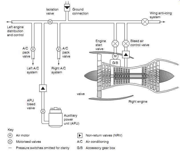
FIG. 11 Typical air distribution system
Isolation valve; Left engine distribution and control; A/C pack valve; A/C pack valve; Left A/C system; Right A/C system; Engine start valve; G/B M APU bleed valve; Auxiliary power unit (APU); Right engine; Bleed air control valve; Wing anti-icing system; Ground connection; M Air motor; Key; Motorized valves; Pressure switches omitted for clarity A/C G/B; Non-return valves (NRV); Air conditioning; Accessory gear box valve
==============
The circuit is completed through the cut-out contacts in the engine starter valve. The start switch is now held in the GRD position and the ground start sequence is initiated. The 28 V DC supply also energizes the start valve solenoid and this opens the valve, supplying air to drive a small turbine in the starter motor. The turbine connects through an accessory gearbox onto the engine's HP compressor shaft.
At approximately 16% of maximum rotational speed, the start lever is moved from the cut-off position to ' idle ' . This applies 28 V DC through a second pair of contacts of the start switch and ignition switch to supply the HEIU. Each igniter plug discharges at a high level, typically 20 joules of energy, at 60-90 discharges per minute. (This can be heard outside the engine as an audible ' clicking ' sound.) At a pre determined cut-out speed, the centrifugal switch in the starter motor opens: the start switch is de-energized and returns (under spring force) to the off position.
The 28 V DC power supply is removed from the HEIU and the start valve motor drives to its closed position.
The engine continues to accelerate to the ground idle speed; this is slightly above self-sustaining speed and occurs when the engine has stabilized. For a twin-shaft axial flow engine, ground idle is typically 60% of the high-pressure (HP) compressor speed.
Low-energy ignition (typically 4 joules of energy, at 30 discharges per minute) is used in certain phases of flight including take-off, turbulence and landing.
Furthermore, if the aircraft is flying through clouds, rain or snow, continuous low-energy ignition is selected on the control panel. This closes a contact on the rotary switch and applies power to a second HEIU input.
In the event of an engine flameout during flight, the crew will attempt an in-flight start of the engine; this requires a modified procedure to that of the ground start. The engine will be wind-milling due to the forward speed of the aircraft. The starter valve and motor are not selected as with the ground start.
Low ignition (LOW IGN) and flight (FLT) are manually selected on the control panel until the engine reaches flight idle speed. In-flight restarts can only be attempted within certain airspeed and altitude limits.
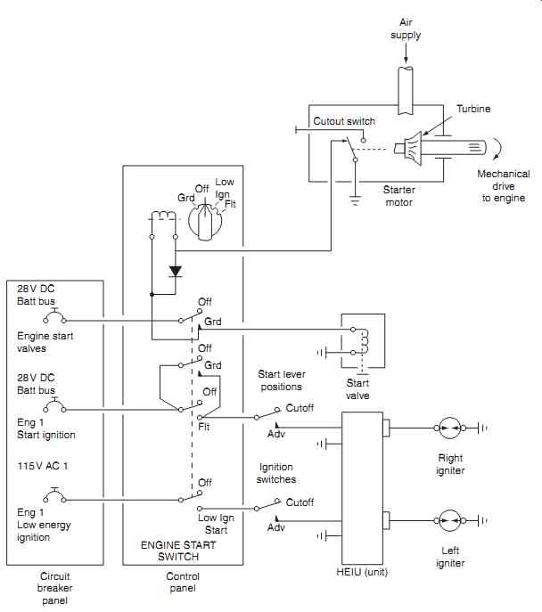
FIG. 12 Turbine starting and ignition system
Key maintenance point
The starting sequence for a gas turbine engine is to: (i) develop sufficient airflow to compress the air, (ii) turn on the ignition, and (iii) open the fuel valves.
This sequence is critical since there must be sufficient airflow through the engine to support combustion before the fuel/air mixture is ignited.
Key maintenance point
Facing the aircraft into the wind augments gas turbine engine starting; this assists with engine acceleration, particularly for turbo-prop engines. The propellers are normally designed with a fine-blade angle for starting and ground running.
Gas turbine engines sometimes suffer from a starting problem that results in fuel entering the combustion chamber, but no ignition; this is sometimes referred to as a wet start. Engine indications would be the engine turning at the correct starter speed, with indications of fuel flow, but no increase in exhaust gas temperature (EGT). Observers outside the aircraft could see atomized fuel or vapor from the engine exhaust.
Test your understanding
Explain the term 'self sustaining speed'.
The cause of a wet start is most likely to be a defective HEIU and/or igniter plug. The net result is no ignition in the combustion chamber and the accumulation of fuel. If compressor outlet air gets hot enough, it could ignite the fuel, causing a rapid expansion of the fuel/air mix (effectively an explosion) that could lead damage of the turbine section and eject flames from the engine exhaust. The procedure is to shut off the fuel supply to the engine and continue turning over the engine with the starter motor to clear (or blow out) out the fuel. Some starter panels have a selectable blow out position to achieve this procedure.
Test your understanding
What is the difference between a flameout and a wet start?
2. Indicating systems overview
Engine indications can be broadly divided into primary and secondary systems. Some indication systems are unique to gas turbine, turboprop or piston engines, some are common to all types. Primary indicators include:
- speed
- temperature
- thrust
- fuel flow
Secondary indicators include (but are not limited to):
- oil temperature
- oil quantity
- oil pressure
- vibration
Measurements are made by a variety of transducers ; these are devices used to convert the desired parameter, e.g. pressure, temperature, displacement etc. into electrical energy. The locations of engine instruments is normally between the two pilot's panels, see FIG. 13 .
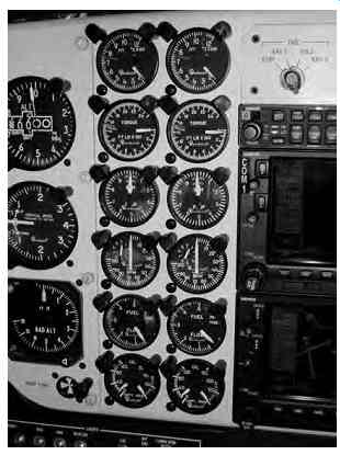
FIG. 13 Typical engine instruments