AMAZON multi-meters discounts AMAZON oscilloscope discounts
Various sensors are needed for the monitoring and control of airframe systems. The indications and/or control circuit need to be informed of the position of a particular feature on the aircraft; this is achieved by a position sensor. Broadly speaking, the sensors can be considered as detecting one of two states (or 'conditions'), or a variable position. Two state conditions include: landing gear (up or down) or cabin doors (open or closed). Variable positions include: control surfaces and flap position. Two state position devices are detected by micro-switches and proximity sensors; variable position devices are detected by a variety of devices including synchros and variable resistors. This section reviews airframe systems such as landing gear control and indication, control surface position and indicating systems.
1. Landing gear
Three control and indicating system configurations are found on aircraft with retractable landing gear (or undercarriage):
-- hydraulic control and operation, electrical indication of position
-- electrical control and operation, electrical indication of position
-- electro-hydraulic control and operation, electrical indication of position
The landing gear comprises two or more wheels and shock absorbers, or oleo legs ; these can be fixed in position or retractable. Large aircraft have hydraulic systems with electrical position sensors for gear up/down indications. General aviation (GA) aircraft normally have electrical control and operation, and electrical indication of position. Operation is via a series-wound split field electrical motor (FIG. 1) driving through to each undercarriage leg via a gear box, torque tubes, cables and pulleys.
The 28V DC power supply is connected to the reversible motor via a safety switch and the position selector switch. This switch operates the landing gear relay via up-lock and down-lock micro switches. When the landing gear starts to retract, the down-lock switch contacts close. When the landing gear is fully retracted the up-lock switch contacts open, and this removes power from the motor. When the landing gear is selected down, the up-lock contacts close and the gear can be extended.
The landing gear safety switch senses when the aircraft is on the ground to prevent the landing gear from being retracted. Some aircraft have a micro-switch (or proximity-sensor ) attached to the oleo leg; when the aircraft is on the ground, the oleo leg is com pressed from the weight of the aircraft; this closes the switch contacts. The switch (or sensor) is now being used to detect the weight on wheels (WoW) ; this is sometimes referred to as a squat switch. When the aircraft takes off, the oleo leg extends when the air craft weight is transferred to the wings and the WoW, or squat switch, opens its contacts. (Note that the switch can actually be configured as normally open or normally closed on the ground depending on the air craft design.) WoW or squat switch contacts are also used by other systems that need to be set into air or ground modes, e.g. to prevent the pitot probes and ice detectors from being heated on the ground.
========
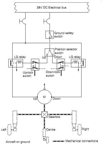
FIG. 1 Landing gear control system
Aircraft on ground; Mechanical connections
=========
Key point: Two state conditions include landing gear (up or down) or cabin doors (open or closed). Landing gear position indication is derived from simple micro-switches in two locations: gear up and gear down. Switches are operated by a cam or lever and this completes the circuit. The quantity of lights depends on the aircraft manufacturer and certification requirements of the aircraft type. The simple system shows if the nose and main gear are up or down with a single indication; it is more usual to have an indication of each gear leg position. Landing gear indications sometimes include an audible warning (klaxon or horn) when the throttles are retarded and the gear is not locked down. The system configuration in widespread use has the following indications:
-- gear down and locked (three green lights)
-- gear up and locked (all three lights out)
-- gear in transit (three red lights)
FIG. 2(a) illustrates a typical landing gear position indication system; note that this system includes additional green lights that can be selected in the event of lamp failure. The circuit is drawn with positions of switches for the aircraft on the ground.
With power applied, the three green lights are illuminated via the down-lock switch. When the gear is selected up, the down-lock switch opens, the green lights extinguish and the three red lights are turned on. When the gear is fully retracted and locked, the red lights are extinguished. When the gear is selected down, the up-lock switch closes, and three red lights come on. With the gear fully down and locked, the down-lock switch closes, the red lights are extinguished and the green lights are switched on. In the event that the throttles are closed (during an approach) and the gear is up, a warning horn will sound.
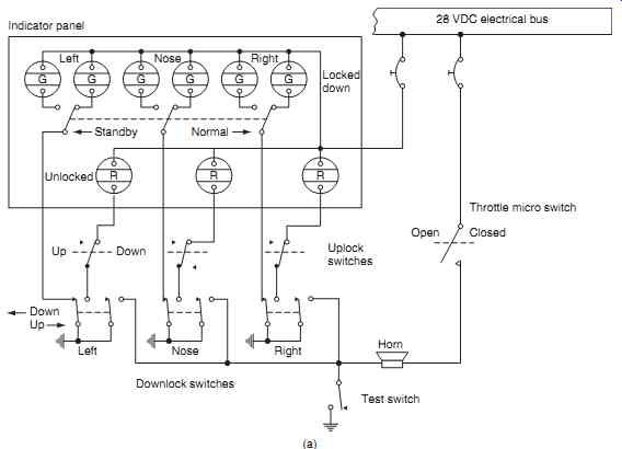
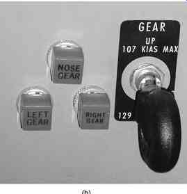
FIG. 2 Landing gear position indication: (a) system schematic, (b) typical
gear position selector and warning lights (general aviation)
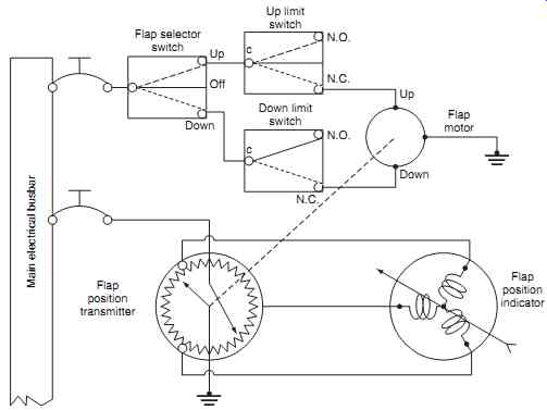
FIG. 3 Trailing edge flaps control and indication. Main electrical busbar
Key point: Indications of landing gear fully down and locked are:
-- red lights off
-- green lights on
Key point: When an electrically operated landing gear is fully retracted, the up-lock switch contacts open, thereby removing power from the motor.
On smaller general aviation aircraft, the system is simplified by having three green lights for gear down and locked (FIG. 2(b)). In this example, the selector switch also has a placard stating the airspeeds for gear selection.
2. Trailing edge flaps
Three configurations are found on aircraft:
-- hydraulic control and operation, electrical indication of position
-- electrical control and operation, electrical indication of position
-- electro-hydraulic control and operation, electrical indication of position
The flap drive motor is a reversible DC motor that drives the flap control mechanism through a gearbox.
GA aircraft have a simple three-position switch identified as OFF/UP/DOWN. The flaps on these aircraft are driven the full extent of travel until they operate up or down limit switches, see FIG. 3.
Selecting ' flaps up ' applies power to the motor through the closed contacts of the up-limit switch; the motor operates and the flaps start to move. The down limit switch changes over as shown by dotted lines, and the flaps travel to the fully retracted position; note that both the limit switches are closed during travel, and this allows the pilot to stop/start the flaps.
Selecting 'flaps down' applies power through the down limit switch and the motor runs in the opposite direction; the up-limit switch changes over to the position shown as solid lines in preparation for the next selection. The flaps continue to travel until they are fully extended and the down-limit switch is operated (solid line). This opens the supply to the motor. Selecting off at any time stops the motor at the given position.
The flap position indicator is an integral part of the system; a mechanical linkage is made between the flap control mechanism and position sensor. This varies the ratio of current in each of three coils in the indicator; flap position is displayed in degrees of flap movement.
Flap position can be from a simple rheostat and ratiometer indication, or from a synchro system. Flaps on larger aircraft are normally driven by a hydraulic system; flap position is selected in specific settings referred to by simple up/down positions, or (on larger aircraft) by angular positions, see FIG. 4. The flap selection switch in this photograph is to the right of the pedestal and, in this example, are also referenced to the maximum airspeed for given flap settings.
Key point: An electrical flap drive system uses a reversible DC motor.
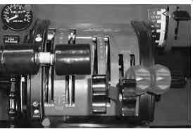
FIG. 4 Flap position selection (top right of photo)
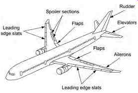
FIG. 5 Flying control surfaces
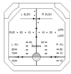
FIG. 6 Control surface position indication
3. Control surfaces
Different aircraft types have a variety of control surface position indicators; the various flying control surfaces on a large passenger aircraft are illustrated in FIG. 5. These control surfaces typically include:
-- leading edge slats
-- spoilers
-- trailing edge flaps
-- rudder(s)
-- elevators
-- ailerons
The position of each control surface can be displayed by an analog indicator (FIG. 6) or form part of an electronic display. Each of the control surfaces is fitted with a position sensor, typically a torque synchro.
Key point: Variable position features include control surface and flap position.
Key point: Two state position devices include micro-switches and proximity sensors.
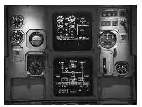
FIG. 7 ECAM displays
=========

FIG. 8 ECAM schematic
- Flying controls
- Synoptics
- FDR
- TCAS
Engine systems
Fuel quantity
- FDR
- TCAS
==========
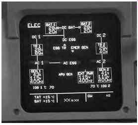
FIG. 9 Electrical system synoptic
4. Electronic indicating systems
The two systems used on the majority of passenger aircraft are EICAS and ECAM. The Engine Indication and Crew Alerting System (EICAS) is a Boeing developed system that provides all engine instrumentation and crew annunciations in an integrated format; this is covered in Section 10 (engine systems). The system used on Airbus aircraft is the Electronic Centralized Aircraft Monitoring (ECAM) system. The two systems operate on different philosophies; however their basic functions are to monitor aircraft systems and display relevant information to the pilots. Both systems produce warning, cautions and advisory messages that need to be evaluated by the crew; in certain cases, the system provides the procedures required to address the problem. Each color display unit uses either an active matrix liquid crystal display (AMLCD) or a cathode ray tube (CRT), see FIG. 7.
ECAM provides the main features of EICAS but also displays corrective action to be taken by the crew as well as system limitations after the failures.
Using a color coded hierarchy, the crew can assimilate the information being presented and take the necessary corrective action. ECAM was first introduced in the Airbus A320 and provides the paper less cockpit since procedures for abnormal and emergency situations are presented on each of the displays.
ECAM comprises a series of integrated systems that display information to the crew in an efficient way. Referring to FIG. 8, aircraft sensors are categorized into key monitoring functions; these sensors transmit data into two system data acquisition concentrators (SDAC). The data is processed and supplied into flight warning computers (FWC). The FWCs are programmed to identify any inconsistencies in the data, and then output the data through three display management computers (DMC).
If system fault or event is detected, one of the FWCs generates the appropriate warning messages and aural alerts. Critical systems such as engine and fuel quantity are routed directly into the FWCs so that they can still be monitored in the event of both SDACs failing. (ECAM can tolerate the a failure of one SDAC and one FWC and still continue to operate.)
The typical synoptic for an electrical system is shown in FIG. 9. In this illustration, the power sources supplying specific busbars is shown graphically, together with information such as battery and transformer rectifier (TR) unit voltages and supply currents. Generator capacity is shown as a percentage of maximum, together with output voltage and frequency.
Aircraft system failures are prioritized as level 1, 2 or 3 failures for the upper and/or lower display. The warning and caution hierarchy is as follows.
Level 3 failures - red warnings: these are situations that require immediate crew action and indicate that the aircraft is in danger. Examples of level 3 failures include an engine fire or loss of cabin pressure. Level 3 system failures illuminate the red master warning light, a warning (red) ECAM message and an aural warning; this can be a continuous repetitive chime, a specific sound or a synthetic voice. Pressing the master warning push button silences the aural warning.
Level 2 failures - amber cautions: these are situations that require crew attention but not immediate action. Examples of level 2 failures include bleed air failure or a fuel system fault. Level 2 failures have no immediate or direct impact on flight safety; cautions are displayed to the crew by an amber master caution light, an amber ECAM message and a single chime.
Level 1 failures - these are system failures and/or faults that could lead to a loss of system redundancy.
Level 1 failures require monitoring but have no immediate impact on continued safe operation of the aircraft. Examples of level 1 failures include the loss of a fuel system temperature sensor. Level 1 failures are displayed to the crew by amber ECAM messages only (no aural warning).
5. QUIZ--Multiple choice questions
1. Indications of landing gear fully down and locked are:
(a) red lights on, green lights off
(b) red lights on, green lights on
(c) red lights off, green lights on
2. Two state conditions include:
(a) flap position or doors (open or closed)
(b) landing gear (up or down) or doors (open or closed)
(c) landing gear (up or down) or control surface position
3. An electrical flap drive system uses a:
(a) reversible DC motor
(b) variable speed DC motor
(c) unidirectional DC motor
4. Level 3 ECAM failures are indicated by:
(a) red warnings, requiring immediate crew action
(b) amber cautions, requiring crew attention
(c) red warnings, having no immediate impact on the aircraft.
5. Variable position features include:
(a) doors (open or closed) and flap position
(b) control surface and proximity sensor position
(c) control surface and flap position
6. When an electrically operated landing gear is fully retracted, the up-lock switch contacts:
(a) open, thereby removing power from the motor
(b) close, thereby removing power from the motor
(c) open, thereby applying power to the motor
7. Engine fire or loss of cabin pressure would be displayed on ECAM as:
(a) level 3 failures
(b) level 2 failures
(c) level 1 failures.
8. Two state position devices include:
(a) micro switches and variable resistors
(b) synchros and proximity sensors
(c) micro switches and proximity sensors
9. Electrically driven flaps continue to travel until they are:
(a) fully retracted and the down-limit switch is operated
(b) fully extended and the down-limit switch is operated
(c) fully extended and the up-limit switch is operated.
10. Variable position devices include:
(a) synchros and variable resistors
(b) micro switches and variable resistors
(c) synchros and proximity sensors