AMAZON multi-meters discounts AMAZON oscilloscope discounts
(cont. from part 1)
6. Fiber optics
Another technology adopted for IFE is based on fiber optics. This technology has been widely used as a transmission medium for ground-based data communications and in local area networks (LAN) for many years and they are now being introduced into passenger air craft to satisfy the need for wideband networked avionic and cabin entertainment systems. Compared with cop per wiring, optical fibers have a number of advantages:
--reduced weight, compact size
-- immunity to electromagnet interference (EMI)
-- exceptionally wide bandwidth
-- significantly reduced noise and cross-talk
--relatively low values of attenuation within the medium
-- high reliability coupled with long operational life
-- electrical isolation and freedom from earth/ground loops
These advantages mean that optical fibers are ideally suited as a replacement for conventional copper net work cabling. The technology is relatively new in the civil aircraft industry and introduces new challenges for those involved with aircraft operation and maintenance. There are a number of disadvantages for optical fibers; these include:
-- industry resistance to the introduction of new technology
-- need for a high degree of precision when fitting cables and connectors
-- concerns about the mechanical strength of fibers
-- cable bends need to have a sufficiently large radius to minimize losses and damage
The advantages are now outweighing the disadvantages and systems based on optical fibers are being installed on many aircraft types. A simple one-way (simplex) fiber optic data link is shown in FIG. 7. The optical transmitter consists of an infrared light-emitting diode (LED) or low-power semiconductor laser diode coupled directly to the optical fiber. The diode is supplied with pulses of current from a bus interface.
These pulses of current produce equivalent pulses of light that travel along the core of the fiber until they reach the optical receiver unit. The optical receiver unit consists of a photodiode or phototransistor that passes a relatively large current when illuminated and negligible current when not. The pulses of current at the transmitting end (logic inputs) are thus replicated at the receiving end (as logic outputs). Cladding is a layer of material with a lower refractive index than the core, and confines the optical signal inside the core.
6.1 Construction
The construction of a typical fiber optic cable is shown in FIG. 8 ; in this example, the cable consists of:
1. an outer jacket
2. aramid yarn (strength member)
3. separator tape (polyester)
4. two filler strands
5. five optical fibers.
Key maintenance point
Fiber optic cable bends need to have a sufficiently large radius to minimize signal losses and physical damage.
=======

FIG. 7 Fiber optic cable connector
Core; Cladding; Optical fiber; Optical receiver; Logic output; Optical transmitter; Logic input
=======
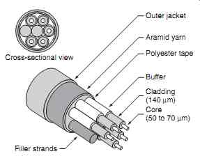
FIG. 8 (Simplex) fiber optic data link
Outer jacket Aramid yarn Polyester tape Buffer Cladding (140 µm) Core (50 to 70 µm) Cross-sectional view Filler strands
=======
A protective buffer covers each fiber and protects it during manufacture, increases mechanical strength and diameter in order to make handling and assembly easier.
The buffers are coded in order to identify the fibers using colors (blue, red, green, yellow and white). The filler strands are made from polyester and are approximately 0.035 inches in diameter. A polyester separator tape covers the group of five fibers and two filler strands. This tape is manufactured from low-friction polyester and it serves to make the cable more flexible. A layer of woven aramid (or Kevlar) yarn provides added mechanical strength and protection for the cable assembly. The outer thermoplastic jacket (usually purple in color) is fitted to prevent moisture ingress and also to provide insulation. A typical fiber optic cable connector arrangement is shown in FIG. 9.
6.2 Connectors
Each connector has alignment keys on the plug and matching alignment grooves on the receptacle. These are used to accurately align the connector optical components; the guide pins in the plug fit into cavities in the receptacle when the plug and receptacle connect. In order to ensure that the connector is not over-tightened (which may cause damage to the fibers) the pins of the plug are designed to provide a buffer stop against the bottom of the cavities in the receptacle. Plugs and receptacles have ceramic contacts that are designed to make physical contact when properly connected.
The light signal passes through holes in the end of the ceramic contacts when they are in direct physical contact with each other. The coupling nut on the plug barrel has a yellow band whilst the receptacle barrel has a red and a yellow band. A correct connection is made when the red band on the receptacle is at least 50 percent covered by the coupling nut. This position indicates an effective connection in which the optical fibers in the plug are aligned end-to-end with the fiber in the receptacle. Three start threads on the plug and receptacle ensure a straight start when they join.
The recessed receptacle components prevent damage from the plug if it strikes the receptacle at an angle.
The plug and receptacle are automatically sealed in order to prevent the ingress of moisture, dust and other contamination. Color-coded bands ensure that the plug and receptacle are fully mated. (The subject of optical fibers is covered in more detail in Aircraft Digital Electronic and Computer Systems, a companion volume.)
Key point
The optical fiber receiver unit consists of a photodiode or phototransistor that passes a relatively large current when illuminated and negligible current when not illuminated.
7. Air conditioning
Air conditioning is provided in passenger aircraft for the comfort of passengers. The cabin on larger aircraft is divided into passenger compartment locations, or temperature control zones, see FIG. 10. Air conditioning, and the environmental control system (ECS), normally derive high-pressure air from the compressor stage of each turbine engine. The temperature and pressure of this bleed air varies, depending upon rotational speed of the engine. A pressure-regulating shutoff valve (PRSOV) restricts the flow as necessary to maintain the desired pressure for the ECS.
=====
Coupling ring; Thread; Yellow; Red; Yellow
=====
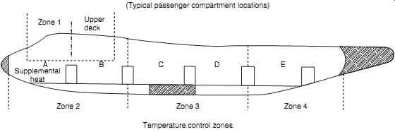
FIG. 10 Air conditioning: passenger cabin zones
Zone 2 Supplemental heat AB CD E Zone 1 Upper deck Zone 3 Temperature control zones (Typical passenger compartment locations) Zone 4
========
7.1 Environmental control system
To increase efficiency of the ECS, air is normally bled from two or three positions on the engine. Aircraft types vary, but the principles of air conditioning systems comprise five salient features:
-- air supply
-- heating
-- cooling
-- temperature control
-- distribution
The air conditioning system is based on an air cycle machine (ACM) cooling device as illustrated in FIG. 11. The air conditioning packs ( A/C packs ) are located in varying places on aircraft, including:
-- between the two wings in the lower fuselage
-- in the rear fuselage tail section
-- in the front of the aircraft beneath the flight deck
Engine bleed air, with temperatures in the order of 150 and 200°C and a pressure of between 30-35 pounds per square inch (psi), is directed into a primary heat exchanger. External ram air (at ambient temperature and pressure) is the cooling medium for this air-to air heat exchanger. The cooled bleed air then enters the centrifugal compressor of the air cycle machine (ACM). This compression heats the air (the maximum air temperature at this point is about 250°C) and it is directed into the secondary heat exchanger, which again uses ram air as the coolant. Pre-cooling through the primary heat exchanger increases the efficiency of the ACM by reducing the temperature of the air entering the compressor; less work is required to compress a given air mass (the energy required to compress a gas by a given ratio increases with higher temperature of the incoming air).
At this stage, the temperature of the heat exchanger air is higher than the outside air temperature; the temperature is sensed by an RTD and this is displayed on the air conditioning control panel and/or used as part of a control system input. The compressed, cooled air is then directed into the expansion turbine of the ACM; this extracts work from the air as it expands, cooling it to between _ 20°C and _ 30°C. (The ACM can cool the air to less than 0°C even when the aircraft is on the ground in a high ambient temperatures.) The work extracted by the turbine drives a shaft to turn the ACM's centrifugal compressor, together with a ram air inlet fan that draws in the external air during ground running. A motorized bypass valve controls the ratio of air being directed into the turbine. An electrically driven ram air fan within the system provides air flow across the heat exchangers when the aircraft is on the ground. To assist ram air recovery, some aircraft use modulating vanes on the ram air exhaust. Power for the air conditioning pack is obtained by reducing the pressure of the incoming bleed air relative to the cooled air output of the system.
========
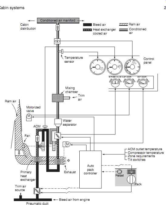
FIG. 11 Air conditioning system
Auto pack controller; Mixing chamber; Trim air; Temperature sensor; Water separator; Motorized valve; Ram air; Fan; ACM; Primary heat exchanger; Trim air source; Pneumatic duct; Exhaust; M; M Bleed air from engine; Conditioned air manifold Cabin distribution; Control panel; BYPASS VALVE INLET DOOR EXIT DOOR COOL HEAT COOL HEAT COOL HEAT; ACM outlet temperature; Compressor temperature; Zone requirements Tilt switches Pack Reset Bleed air Ram air Conditioned air Heat exchanger cooled air
=========
Test your understanding
What type of sensor is used for regulation of cabin air temperature?
With the air now cooled, its water vapor condenses.
To remove this, the moist air output of the expansion turbine is passed through a water separator; this uses centrifugal force to eject the water particles into a coalescing bag that absorbs the moisture. This condensate is sometimes fed back into the ram air entering the secondary heat exchanger to improve its performance.
The cool dry air is now combined in a mixing chamber with a small amount of engine bleed air; the amount of trimming air mixed with cooled air is modulated to achieve the desired cabin air temperature before the air is ready for supply into the cabin. An RTD is installed to monitor the ACM outlet temperature; airflow into the cabin is monitored by a flow sensor.
The A/C pack outlet air for use in the cabin is mixed with filtered air from re-circulation fans, and then fed into the mixing manifold. On modern passenger aircraft, the airflow into the cabin is approximately 50% bleed air and 50% filtered air. Control of the air conditioning system on a Boeing 757 aircraft is from an overhead control panel, see FIG. 12.
Key point
To assist ram air recovery, some aircraft use modulating vanes on the ram air exhaust.
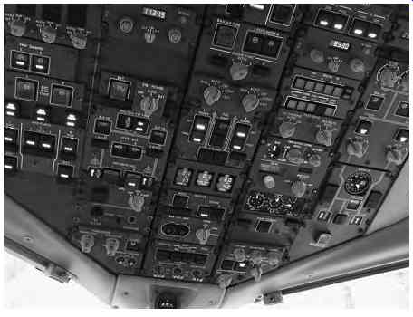
FIG. 12 Air conditioning system control (right/center of overhead panel)
7.2 Ventilation
A re-circulation fan is used to re-circulate filtered cabin air back into the cabin to reduce bleed air requirements. Up to 50% of the cabin air can re circulated for passenger comfort. The fan will switch off if either A/C pack is in high flow, giving a net reduction in the ventilation rate. Optimum cooling and reduced bleed air demand (hence reduced fuel consumption) is achieved with a combination of air re-circulation and automatic operation of the A/C packs.
The ventilation rate is increased on larger aircraft with additional re-circulation fans for comfort levels.
Some aircraft are installed with a gasper fan ; this is an electric fan designed to increase pressure in the outlets above passenger seats. The gasper fan is typically used when there is a:
-- low supply of air pressure
-- high cold air demand
-- high ambient temperature (on the ground on a hot day)
When the A/C packs are off, the gasper fan draws cabin air into the distribution ducts, into the main air manifold and mixing chamber where it is then blown (albeit not chilled) into the cabin.
7.3 Equipment cooling
Although not part of the cabin system for the comfort of passengers, some aircraft are installed with equipment cooling that takes air from the cabin system.
Equipment cooling can be used for:
-- flight compartment panels
-- display units
-- circuit breaker panels
-- electrical and electronic (E & E) bay
Replacing the warm air generated by equipment with cool air from the cabin is achieved with dedicated electric fans. On the ground, the air is directed over board through the flow control or exhaust valves.
During flight, the warm air generated by equipment is sometimes used for heating the cargo holds by exhausting air around their walls.
=========
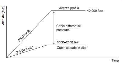
FIG. 13 Cabin pressurization/altitude chart
2000 ft/min 2-700 ft/min; Cabin differential pressure; Cabin altitude profile; Aircraft profile; 40,000 feet 6500-7000 feet; Altitude (feet); Time
=========
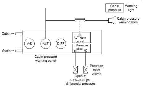
FIG. 14 Cabin pressurization warning
Cabin pressure; Warning light; Cabin pressure warning horn;
Pressure relief valves; Open at 9.25-9.70 psi differential pressure
=========
8. Pressurization
In addition to temperature control, aircraft flying at high altitudes need to be pressurized since the amount of oxygen in the atmosphere decreases with altitude.
The effects of insufficient oxygen on people can begin as low as 1500 m (5000 ft) above sea level, although most passengers can tolerate altitudes of 2500 m (8000 ft) without ill effect. At this altitude, there is approximately 25% less oxygen compared to sea level. Flight operations above 3000 m (10,000 ft) generally require supplemental oxygen; this is achieved through pressurization on passenger aircraft.
The relationship between cabin pressure and atmospheric pressure is illustrated in FIG. 13. Cabin pressure is controlled automatically; this is managed by the crew via a control panel as illustrated in FIG. 12. Pressurization is monitored and warnings provided in the event of a malfunction. Fig. 14 illustrates a typical warning system schematic; this illuminates a warning light on the master caution panel and sounds a horn in the event of reduced cabin altitude.
Engine bleed air is supplied into the cabin and then allowed to pass out of the fuselage via outflow valves (OFV). Most aircraft have a single OFV located near the bottom aft end of the fuselage; some larger air craft have two. By modulating the position of the out-flow valve(s), the pressurization in the cabin can be maintained higher than atmospheric pressure. Modern commercial aircraft have a dual channel electronic controller for maintaining pressurization, with a manual back-up system. These systems maintain cabin air pressure at the equivalent to 2500 m (8000 ft) at high cruising altitudes.
A positive pressure relief valve opens in the event of excessive pressure in the cabin; this protects the aircraft structure from excessive loading. The maxi mum pressure differential between the cabin and atmospheric pressure is between 7.5 and 8 psi. This is the equivalent of approximately 10,000 feet; if the cabin were maintained at sea level pressure and then operated at cruise altitude, the differential would be the structural life of the aircraft would be reduced
Key point
Bleeding air from the engine comes at the expense of overall aircraft efficiency. Some aircraft such as the Boeing 787 are now using electrically driven compressors to provide pressurization.
A pressurization failure above 10,000 ft results in an emergency situation; the cabin pressure might be 10 psi, while the atmospheric pressure is only 2 psi. The pilot must make an emergency descent and activate oxygen masks for everyone aboard. In most passenger aircraft, oxygen masks are automatically deployed if the cabin pressure drops below an equivalent cabin altitude of 14,000 feet. Gradual decompression is dangerous to all on board since it may not be detected. Rapid decompression causes the lungs to decompress faster than the cabin. Explosive decompression is when cabin pressure reduces faster than the lungs can decompress (less than 0.5 seconds). Rapid decompression of commercial aircraft is extremely rare, but the results are life-threatening.
Furthermore, the air temperature will rapidly fall due to the expansion of the cabin air, potentially resulting in frostbite.
Key point
Aircraft cabin pressure is commonly referred to as a 'cabin altitude', typically 8000 feet or less, therefore a lower cabin altitude relates to a higher pressure.
Key point
The cargo compartment is normally pressurized to the same level as the cabin; the temperature in this compartment may be controllable depending on the nature of cargo being carried.
9. Airstairs
These are located in either forward or aft cabin locations, and can be raised or lowered while the aircraft is on the ground. Airstairs allow passengers, flight crew and ground personnel to board or depart the aircraft without the need for a mobile staircase or access to a terminal.
On forward door positions, the stair folds and stows directly into the floor, beneath the door. This type of airstair is found on many short-range aircraft to provide operational flexibility, although the stairs are quite heavy; many airlines remove this system to reduce aircraft weight. Ventral airstairs are fitted on most tail-engine airliners, and are incorporated as ramps which lower from the rear fuselage.
They can be operated from either internal or external control panels; both panels typically have normal and standby systems. Normal operation requires both AC and DC power, standby only requires DC power.
External standby system power typically comes directly from the battery bus and so does not require the battery switch to be on. Airstairs should not be operated more than is necessary to prevent the motors from overloading; their typical duty cycle is three consecutive cycles of normal system operation within a 20 minute period.
10. Multiple choice questions
1. Multiplexing is a technique used for:
(a) increasing the amount of IFE wiring to a seat position
(b) reducing the amount of IFE wiring to a seat position
(c) increased immunity to electromagnet interference (EMI)
2. Fiber optic cable bends need to have a sufficiently large radius to:
(a) minimize losses and damage
(b) maximize immunity to electromagnet interference (EMI)
(c) accurately align the connector optical components.
3. ACM outlet temperature is measured using:
(a) a Bourdon tube
(b) an RTD
(c) a thermocouple.
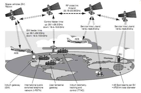
4. The Iridium network allows voice and data messages to be routed:
(a) anywhere in the world
(b) between the flight crew and cabin crew
(c) via a fiber optic network.
5. The passenger address (PA) system is primarily a safety system that provides passengers with:
(a) in-flight entertainment
(b) reduced amount of IFE wiring to a seat position
(c) voice announcements and chime signals
6. To assist ram air recovery, some aircraft use:
(a) modulating vanes on the ram air exhaust
(b) modulating vanes on the ram air inlet
(c) modulating vanes on the ACM outlet.
7. Satellite communication systems use a low earth orbit to:
(a) provide greater coverage
(b) maintain a geostationary position
(c) minimize voice delays
8. Audio-video on demand (AVOD) entertainment enables passengers to:
(a) pause, rewind, fast-forward or stop a program
(b) make phone calls via satellite communication
(c) ignore PA system voice announcements and chime signals.
9. Supplemental oxygen is generally required flight operations above:
(a) 3000 ft
(b) 10,000 ft
(c) sea level
10. The optical fiber receiver unit consists of a photodiode or phototransistor that passes a:
(a) relatively large current when illuminated and negligible current when not illuminated
(b) relatively small current when illuminated and high current when not illuminated
(c) relatively small current when illuminated and low current when not illuminated
11. The gasper fan is used in cabin ventilation systems to:
(a) increase air pressure in the air outlets
(b) re-circulate filtered cabin air
(c) assist with ram air recovery.
12. Cabin altitude is typically
(a) cruising altitude
(b) sea level
(c) between 6-7000 feet.
13. The cargo compartment is normally pressurized to be:
(a) equal to cabin pressure
(b) above cabin pressure
(c) below cabin pressure.
14. Referring to FIG. 15, cladding is used in fiber optic cables to:
(a) protect the fiber
(b) prevent moisture ingress
(c) guide the light signal.
15. Referring to FIG. 16, the iridium system transfers messages around the world:
(a) directly between satellites
(b) via gateways on the earth's surface
(c) directly between users.
16. The iridium system satellite orbits are:
(a) random
(b) equatorial
(c) polar.
======
Core Cladding Optical fiber Optical receiver Logic output Optical transmitter Logic input
======


